

MTS Sensors Level Plus SoCLEAN, SoCLEAN Level Plus, Level Plus RefineME Operation Manual
Operation Manual
Level Plus
®
Magnetostrictive Liquid Level Transmitters
with Temposonics® Technology
SoCLEAN
®

Table of contents
1. Contact information ........................................................................................................................................... 3
2. Terms and definitions ......................................................................................................................................... 3
3. Introduction ..................................................................................................................................................... 5
3.1 Purpose and use of this manual ................................................................................................................................................................ 5
3.2 Used symbols and warnings ..................................................................................................................................................................... 5
4. Safety instructions ............................................................................................................................................. 5
4.1 Intended use .............................................................................................................................................................................................. 5
4.3 Installation, commissioning and operation ................................................................................................................................................ 6
5. Product overview .............................................................................................................................................. 6
5.1 Components .............................................................................................................................................................................................. 6
4.2 Foreseeable misuse ................................................................................................................................................................................... 6
5.2 Accuracy .................................................................................................................................................................................................... 8
5.3 Warranty .................................................................................................................................................................................................... 8
5.4 Storage ...................................................................................................................................................................................................... 8
5.5 Model number identification ...................................................................................................................................................................... 9
5.6 Technical data .......................................................................................................................................................................................... 11
6. Installation and mounting ...................................................................................................................................12
6.1 Training ...................................................................................................................................................................................................12
6.2 Stilling wells and guide poles .................................................................................................................................................................. 12
6.3 Tools ........................................................................................................................................................................................................12
6.4 Installation steps ..................................................................................................................................................................................... 12
6.5 Mounting ................................................................................................................................................................................................. 12
7. Electrical connections ........................................................................................................................................ 13
7.1 Basic information .................................................................................................................................................................................... 13
7.2 Safety recommendations ......................................................................................................................................................................... 13
7.3 Industrial topologies ................................................................................................................................................................................ 13
7.4 Cable recommendations .......................................................................................................................................................................... 14
7.5 Electrical conduit ..................................................................................................................................................................................... 14
7.6 Grounding ............................................................................................................................................................................................... 15
7.7 Safety barriers ......................................................................................................................................................................................... 16
8. Commissioning................................................................................................................................................16
8.1 Training ...................................................................................................................................................................................................16
8.2 Tools ........................................................................................................................................................................................................16
8.3 Setup software ........................................................................................................................................................................................ 16
8.4 Commissioning steps .............................................................................................................................................................................. 16
9. Maintenance ................................................................................................................................................... 17
9.1 Training ...................................................................................................................................................................................................17
9.2 Tools ........................................................................................................................................................................................................17
9.3 Inspection ................................................................................................................................................................................................ 17
9.4 Preventative maintenance ........................................................................................................................................................................ 17
10. Repair ......................................................................................................................................................... 18
10.1 RMA policy ............................................................................................................................................................................................ 18
10.2 Training .................................................................................................................................................................................................18
10.3 Tools ......................................................................................................................................................................................................18
10.4 Troubleshooting..................................................................................................................................................................................... 19
10.5 Setup software ...................................................................................................................................................................................... 19
11. Spare Parts ................................................................................................................................................... 19
12. Interface ......................................................................................................................................................19
12.1 Modbus ................................................................................................................................................................................................. 19
12.2 DDA ....................................................................................................................................................................................................... 19
12.3 HART
®
.................................................................................................................................................................................................. 19
13. Agency information .........................................................................................................................................20
13.1 Approvals overview ............................................................................................................................................................................... 20
13.2 Certificates ............................................................................................................................................................................................ 22
13.3 FM (NEC) ............................................................................................................................................................................................... 22
13.4 FMC (CEC) ............................................................................................................................................................................................. 32
13.5 ATEX and IECEx ..................................................................................................................................................................................... 46

Level Plus® SoClean
®
Operation Manual
I 3 I
1. Contact information
United States
General
Tel: +1-919-677-0100
Fax: +1-919-677-2343
E-mail: info.us@mtssensors.com
http://www.mtssensors.com
Mailing and shipping address
MTS Systems Corporation
Sensors Division
3001 Sheldon Drive
Cary, North Carolina, 27513, USA
Customer service
Tel: +1-800-633-7609
Fax: +1-800-498-4442
E-mail: info.us@mtssensors.com
Technical support and applications
24 Hour Emergency Technical Support
Tel: +1-800-633-7609
E-mail: levelplus@mts.com
Germany
General
Tel: +49-2351-9587-0
Fax: +49-2351-56491
E-mail: info.de@mtssensors.com
http://www.mtssensors.com
Mailing and shipping address
MTS Sensor Technologie, GmbH & Co. KG
Auf dem Schüffel 9
58513 Lüdenscheid, Germany
Technical support and applications
Tel: +49-2351-9587-0
E-mail: info.de@mtssensors.com
http://www.mtssensors.com
2. Terms and definitions
6A Heavy Oils
‘Generalized Crude Oils’, Correction of Volume to 60 °F against API
Gravity.
6B Light Oils
‘Generalized Products’, Correction of Volume to 60 °F against API
Gravity.
6C Chemical
‘Volume Correction Factors (VCF)’ for individual and special
applications, volume correction to 60 °F against thermal expansion
coefficients.
6C Mod
An adjustable temperature reference for defining VCF.
A
API gravity
The measure of how heavy or light a petroleum liquid is compared to
water. Allowable values are 0 to 100 degrees API for (6A) and 0 to 85
degrees API for (6B).
D
DDA (Direct Digital Access)
The proprietary digital protocol developed by MTS for use in
intrinsically safe areas.
Density
Mass divided by the volume of an object at a specific temperature. The
density value should be entered as lb / cu. ft..
E
Explosion proof
Type of protection based on enclosure in which the parts which can
ignite an explosive gas atmosphere are placed within, and which
can withstand the pressure developed during an internal explosion
of an explosive mixture, and which prevents the transmission of the
explosion to the explosive gas atmosphere surrounding the enclosure.
F
Flameproof
Type of protection based on enclosure in which the parts which can
ignite an explosive gas atmosphere are placed within and which can
withstand the pressure developed during an internal explosion of
an explosive mixture, and which prevents the transmission of the
explosion to the explosive gas atmosphere surrounding the enclosure.

Level Plus® SoClean
®
Operation Manual
I 4 I
G
GOVI (Gross Observed Volume of the Interface)
The total volume of the tank occupied by the interface liquid. The
GOVI is only given when measuring two liquids and is calculated by
subtracting the volume of the product from the total volume of liquid
in the tank (GOVT – GOVP).
GOVP (Gross Observed Volume of the Product)
The total volume of the tank occupied by the product liquid. When
measuring only one liquid, it is also the total volume of liquid
in the tank (GOVT). When measuring two liquids it is the total
volume of liquid in the tank minus the volume of the interface liquid
(GOVT–GOVI).
GOVT (Total Gross Observed Volume)
The total volume of liquid in the tank. When measuring only one liquid
it is equal to the volume of the product (GOVP). When measuring two
liquids it is equal to the volume of the product and interface liquids
(GOVP + GOVI).
GOVU (Gross Observed Volume Ullage)
The difference in volume between the working capacity of a tank and
the total volume in the tank (Working Capacity – GOVT).
H
HART
®
A Bidirectional communication protocol that provides data access
between intelligent field instruments and host systems.
I
Interface
Noun; The measurement of the level of one liquid when that liquid is
below another liquid.
Interface
Adj.; The Software Graphical User Interface (GUI) that allows the user
to access software protocols (HART
®
, DDA, MODBUS).
Intrinsic safety
‘Intrinsically safe’ - Type of protection based on the restriction of
electrical energy within apparatus of interconnecting wiring exposed to
potentially explosive atmosphere to a level below that which can cause
ignition by either sparking or heating effects.
M
Mass
The property of a body that causes it to have weight in a gravitational
field, calculated by density at the reference temperature multiplied by
the volume correction factor (Density × VCF).
MODBUS
A serial communications protocol published by Modicon in 1979 for
use with its programmable logic controllers (PLCs). It has become a
de facto standard communications protocol in industry, and is now the
most commonly available means of connecting industrial electronic
devices.
N
NEMA Type 4X
A product Enclosure intended for indoor or outdoor use primarily to
provide a degree of protection against corrosion, windblown dust and
rain, splashing water, and hose-directed water; and to be undamaged
by the formation of ice on the enclosure. They are not intended to
provide protection against conditions such as internal condensation or
internal icing.
NPT
U.S. standard defining tapered pipe threads used to join pipes and
fittings.
NSVP (Net Standard Volume of the Product)
The temperature corrected volume for the product liquid in the tank,
requires the transmitter to be ordered with temperature measurement
capabilities. The NSVP is calculated by multiplying the volume of the
product liquid by a volume correction factor based on temperature
(GOVP × VCF).
R
Reference Temperature
The temperature at which the density measurement is given, the
allowable values are 32 °F to 150 °F (0 °C to 66 °C).
S
Specific Gravity
The density ratio of a liquid to the density of water at the same
conditions.
Sphere Radius
The internal radius of the sphere that contains the liquid, the value is
used to calculate the volume along with the Sphere Offset.
Sphere Offset
An offset value that accounts for additional volume in a sphere from
non-uniform sphere geometry, the value is used to calculate the
volume along with the Sphere Radius.
Level Plus® SoClean
®
Operation Manual
I 5 I
Strap Table
A table of measurement correlating the height of a vessel to the
volume that is contained at that height. The transmitter can contain up
to 100 points.
T
TEC
‘Thermal Expansion Coefficient’ - a value correlating the change in
temperature for an object with the change in its volume. Allowable
values are 270.0 to 930.0. TEC units are in 10 E-6/Deg F.
Temperature Correction Method
One of five product correction methods used to correct the product
volume in the tank due to changes in temperature from 60 °F including
(6A, 6B, 6C, 6C Mod, and Custom Table.
V
Volume Calculation Mode
One of two methods use to calculate volume measurements from level
measurements, including Sphere and Strap Table.
VCF (Volume Correction Factor)
A table of measurements correlating temperature points with
correction factors for the liquids expansion/contraction. The
transmitter can contain up to 50 points.
W
Working Capacity
The maximum volume of liquid that the user desires for their vessel to
hold, typically 80% of the vessels maximum volume before overfill.
3. Introduction
3.1 Purpose and use of this manual
Important:
Before starting the operation of the equipment read this
documentation thoroughly and follow the safety information.
The content of this technical documentation and of its various annexes
is intended to provide information on mounting, installation and
commissioning by qualified service personnel according to IEC 60079-14
and local regulations or MTS trained service technicians.
3.2 Used symbols and warnings
Warnings are intended for your personal safety and for avoidance
of damage to the described product or connected devices. In this
documentation, safety information and warnings to avoid dangers that
might affect the life and health of personnel or cause material damage
are highlighted by the preceding pictogram, which is defined below.
Symbol Meaning
NOTICE
This symbol is used to point to situations
that may lead to material damage and/or
personal injury.
4. Safety instructions
4.1 Intended use
The liquid level transmitter is intended to be used to measure the level
of liquid(s) contained by a structure as well as the temperature of
the liquid. The product may only be used for the applications defined
under item 1 to item 4 and only in conjunction with third-party devices
and components recommended or approved by MTS Sensors. As a
prerequisite of proper and safe operation, the product requires correct
transport, storage, mounting and commissioning and must be operated with utmost care.
1. Application does not exceed product’s performance specification in
chapter 5.6.
2. Product may only be installed in hazardous areas as specified by
approval certifications in chapter 13 following special conditions of
use outlined in chapter 13 or in safe areas.
3. The liquid(s) being measured are compatible with the selected
wetted parts of the product.
4. MTS floats should be used for proper functionality and safety
approval.

Level Plus® SoClean
®
Operation Manual
I 6 I
Forseeable misuse Consequence
Wrong sensor connection Possible damage to electronics
See chapter 7 for Electrical
Connections
Improper Installation Physical damage to packaging
See chapter 6 for installation
Installation in unapproved
Hazardous Area
Potential Spark
See chapter 13 for Agency
Information
Process Temperature out of range Signal degradation, possible
damage to sensor
See chapter 5.6 for specications
Power Supply out of range No communication, possible
damage to sensor
See chapter 5.6 for specications
Process Pressure out of range Possible damage to sensor,
See chapter 5.6 for specications
Improper Chemical Compatibility Possible damage to sensor,
customer must select wetted
material that is compatible with
liquid(s) in tank
Modifying Sensor Warranty void, hazardous approv-
al void customer should contact
factory for custom unit
Improper Grounding Possible damage to sensor, full
protection compromised,
See chapter 7.6 for grounding
Table 1: Foreseeable misuse
4.3 Installation, commissioning and operation
1. Wear proper personal protection equipment such as hard hat,
safety shoes, flame resistant clothing, safety glasses, gloves, and
hearing protection.
2. Follow the specifications given in the technical documentation.
3. Two (2) individuals are recommended to conduct proper
installation, commissioning, and repair of the level transmitter.
4. Ensure the equipment used in a hazardous environment is
selected and installed in compliance with regulations governing
the geographical installation and facility. Only install equipment
that complies with the types of protection relevant to the
applicable classes, division, zones, category, gas group, and
temperature code.
5. Protect the sensor against mechanical damage during installation
and operation.
6. Do not use damaged products and secure them against
unintentional use. Mark damaged products as being defective.
7. Connect the sensor very carefully and pay attention to the polarity
of connections. MTS recommends to not make connections while
power is live.
8. Before turning on power, ensure that nobody’s safety is
jeopardized by starting level transmitter and/or process.
9. Regularly follow preventative maintenance to prevent safety risks
4.2 Foreseeable misuse 10. Make sure that no wire strands are loose or sticking out of
the terminal block connection which could short and cause a
problem.
11. Make sure that no wire strands, including shield, are in contact
with the electronic module enclosure.
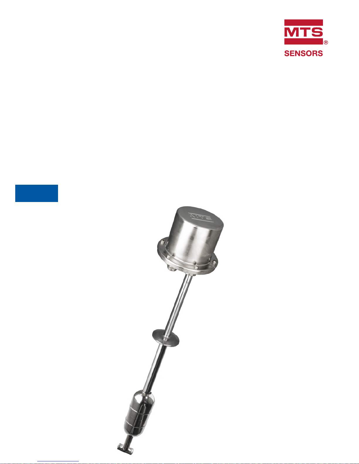
5. Product overview
The Level Plus® Tank Slayer® Liquid-Level transmitter is a continuous
multi-functional magnetostrictive transmitter that provides product
level, interface level, and temperature to the user via Modbus, DDA,
Analog (4…20 mA), or HART
®
. Magnetostrictive technology is one of
the most accurate and repeatable level technologies available to date.
MTS is the inventor and purveyor of magnetostrictive technology and
has been serving the level industry for over 35 years.
Industries
• Pharmaceutical
• Food & Beverage
• Cosmetics
Applications
• Bioreactor
• Day Tanks
• Storage Tanks
Features
• 4-in-1 Measurement
• Product Level
• Interface Level
• Temperature
• Volume
• No scheduled maintenance or recalibration
• Field Repairable
• Inherent Accuracy ±1mm
• 200 Point Strap Table
• API Temperature Corrected Volumes
5.1 Components
The Level Plus
®
Tank Slayer® liquid level transmitter consists of
four main components; a housing, outer pipe, float, and electronics.
Varying the components of the transmitter allows the transmitter to be
customized to almost any application.
Housings
Level Plus
®
Tank Slayer® transmitters are available in three housing
configurations; NEMA Type 4X 316L stainless steel, single and dualcavity housings as shown below:

Level Plus® SoClean
®
Operation Manual
I 7 I
Fig. 1: NEMA Type 4X 316L stainless steel housing
Fig. 2: Single cavity housing
1
2
3
REV
ECO #
DESCRIPTION
TITLE
SIZE
DWG NO.
REV
PRODUCT LINE
BY
DATE
UNLESS OTHERWISE SPECIFIED
TOLERANCES
0 PLACES
MM
1 PLACE
MM
ANGLES
0.5 0.1
- THREAD DEPTHS ARE TO MIN. FULL THDS
- DRILL DEPTHS ARE TO FULL DIA.
- REMOVE BURRS AND SHARP EDGES
- DO NOT SCALE PRINT
PROPRIETARY DATA
THE INFORMATION AND DESIGN(S) DISCLOSED
HEREIN ARE THE PROPERTY OF MTS SYSTEMS
CORPORA
TION AND MAY NOT BE USED,
REPRODUCED OR DISCLOSED IN ANY FORM
EXCEPT AS GRANTED IN WRITING BY MTS
SYSTEMS CORPORATION. THIS RESTRICTION
EXCLUDES INFORMATION THAT IS IN THE
PUBLIC DOMAIN OR WAS LEGITIMATELY IN THE
m
MTS SYSTEMS CORPORATION
SENSORS DIVISION
3001 SHELDON DRIVE, CARY, NC 27513
FIRST
ANGLE
C
LL drawing
DRAWN BY:
114 mm
(4.5 in.)
127 mm
(5 in.)
124 mm
(4.9 in.)
132 mm
(5.2 in.)
87 mm
(3.4 in.)
109 mm
(4.3 in.)
75 mm
(3 in.)
206 mm
(8.1 in.)
127 mm
(5 in.)
117 mm
(4.6 in.)
145 mm
(5.7 in.)
1
2
3
4
114 mm
(4.5 in.)
127 mm
(5 in.)
109 mm
(4.3 in.)
75 mm
(3 in.)
206 mm
(8.1 in.)
127 mm
(5 in.)
117 mm
(4.6 in.)
145 mm
(5.7 in.)
Fig. 3: Dual cavity housing
1
2
75 mm
(3 in.)
206 mm
(8.1 in.)
127 mm
(5 in.)
117 mm
(4.6 in.)
Fig. 4: Stainless steel single cavity housing
Fig. 5: Outer pipe configuration
1
2
3
178 mm
(7 in.)
135 mm
(5.30 in.)
135 mm
(5.3 in.)
152 mm
(6 in.)
1
2
152 mm
(6 in.)
Outer pipe configurations
The outer pipe is constructed of a variety of configurations. The
SoClean
®
is available in a sanitary pipe. For other pipe options please
consult other MTS options such as RefineMe
®
, Tank Slayer®, and/or
USTDII.
1
127mm [5 in ]
Order Length
Pipe diameter (0.625 in. dia)
constructed of 316l stainless steel
Sanitary process connection
(sanitary cap)
Level Plus® SoClean
®
Operation Manual
I 8 I
Floats
SoClean
®
transmitters offer numerous floats for different applications
such as stainless steel, 3-A sanitary, Hastelloy
®
, Teflon, and Nitrophyl
for both product level and interface level. To be able to accurately
detect the interface level there needs to be a difference of at least
0.05in specific gravities between the product and interface liquids.
For detailed information about floats, refer to the ‘Accessories
Catalog’ (MTS Part#551103).
For assistance with selecting a specific float for your application,
please contact technical support with the following information:
• Specific gravity of liquid(s) being measured
• Process temperature
• Process opening size
• Vessel pressure
SoClean
®
transmitters should be used with a float having an offset
weight and made of stainless steel or Hastelloy
®
C. This allows the
float to stay in contact with the pipe to prevent the buildup of an
electrostatic charge. Non-metalic floats with a projected surface area
of less than 5,000 mm² should only be used in Zone 0, Gas group
IIA such as float part numbers 201643-2, 201649-2, 201650-2,
201109, 251115 and 251116. All other non-metallic floats offered by
MTS such as, 251939, 251119 and 251120 should not be used in a
hazardous area application.
Internal electronics
All transmitters come with two electronic components of a sensing
element and a board set. Rigid sensing elements are standard on
SoClean
®
. Flexible sensing elements are available upon request. The
board set consists of up to three electronic boards and a display.
A temperature sensing function is optional with the SoClean®
transmitter. The temperature sensing device is a Digital Thermometer
mounted inside the transmitter’s outer pipe assembly. The SoClean
®
can be ordered with 1, 5, 12, or 16 temperature points.
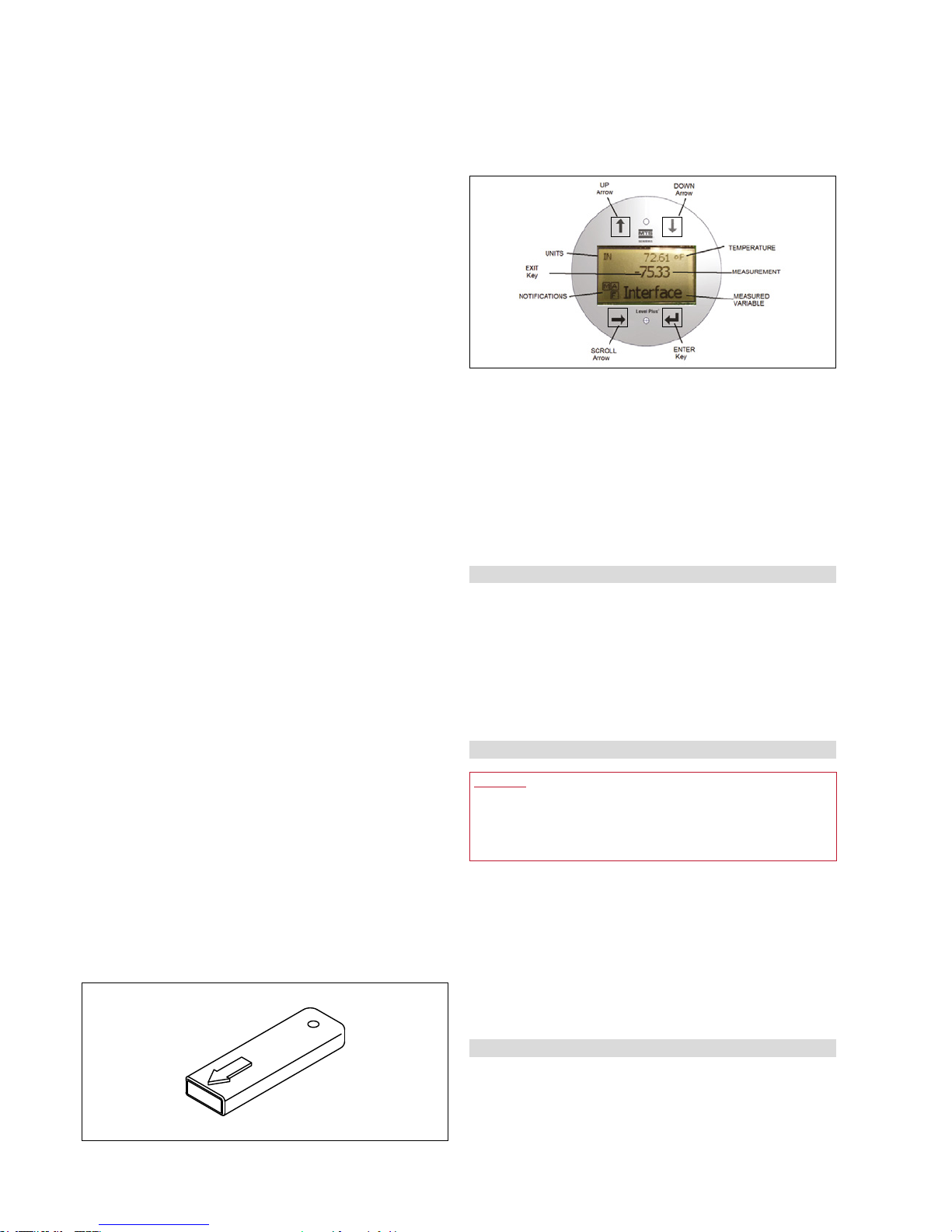
Display
All LP-Series liquid level transmitters are shipped with a stylus (MTS
Part # 404108) to be used for manipulating the display. For single and
dual cavity housings, the stylus is designed to allow for programming
of the unit without removing the housing. When using the stylus make
sure to align the stylus with the shape outline around the buttons in
the same orientation. Failure to correctly align the stylus can cause the
display to not function properly. Password for entering the menu is
27513. For additional details consult the protocol specific Modbus
Interface Manual (MTS Part #551700), DDA Interface Manual (MTS
Part #551701), and HART
®
Interface Manual (MTS Part #551702).
Accessories
MTS also offers a series of displays, housings, converters, and
other accessories, please refer to the ‘Accessories Catalog’ (MTS
Part#551103).
5.2 Accuracy
For magnetostrictive transmitters inherent accuracy is measured
in terms of non-linearity. Non-linearity is a measurement of any
imperfections in the waveguide that are reflected in the linearity of
the transmitter’s output. MTS tolerances reflect a maximum nonlinearity of ±1mm. MTS is able to achieve such strict tolerances by
manufacturing all of its own waveguide from a proprietary alloy and
testing 100% of all transmitters before shipping.
5.3 Warranty
Important:
Contact Technical Support or Customer Service for assistance if
you suspect that the transmitter is not working correctly. Technical
support can assist you with troubleshooting, part replacement, and
Returned Material Authorization (RMA) information if required.
All Level Plus® transmitters come with a two year limited warranty
from the factory shipment date. An additional extended warranty can
be purchased. A Return Materials Authorization (RMA) number is
required and must accompany any transmitter returns. Any unit that
was used in a process must be properly cleaned in accordance with
OSHA standards, before it is returned to the factory. A Material Safety
Data Sheet (MSDS) must also accompany the transmitter that was
used in any process.
5.4 Storage
If storage is required prior to installation, store indoors in a dry
environment at ambient temperature range not to exceed −40…+71°C
(−40…+160°F).
Fig. 6: Stylus (MTS Part # 404108)
Fig. 7: Display
Level Plus® SoClean
®
Operation Manual
I 9 I
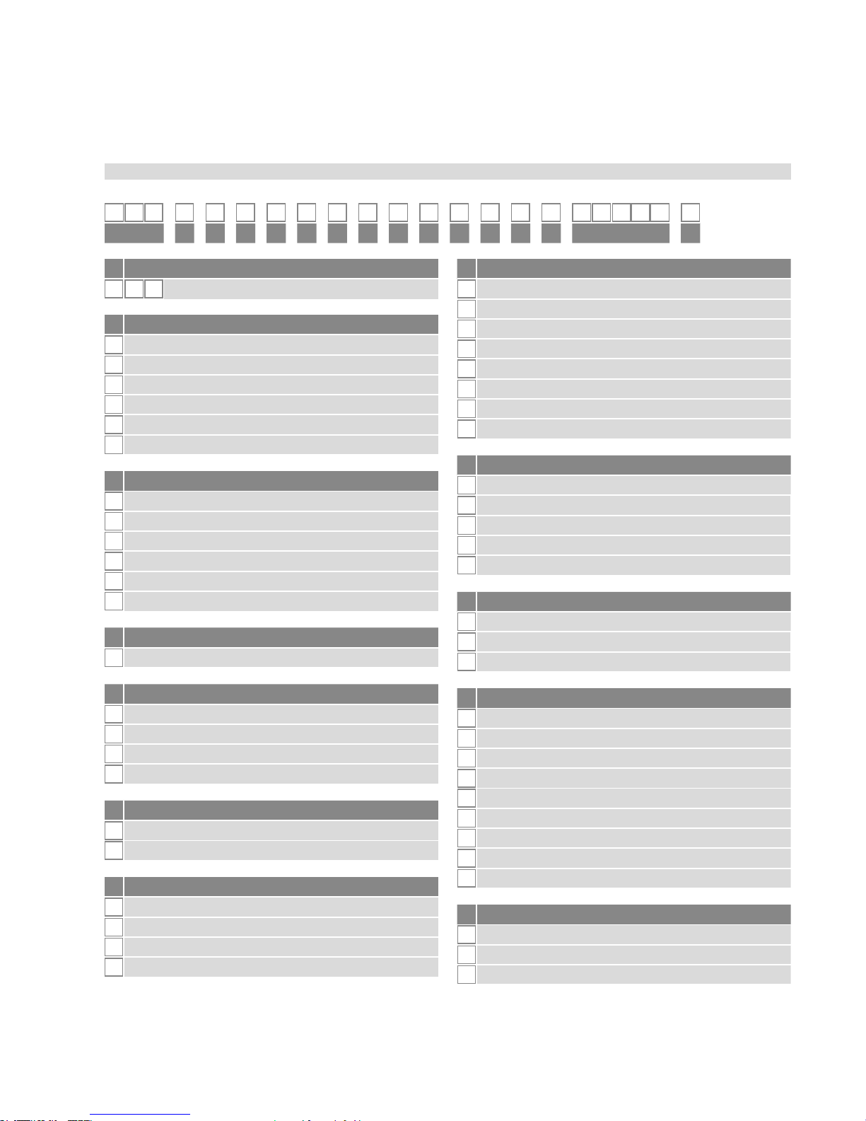
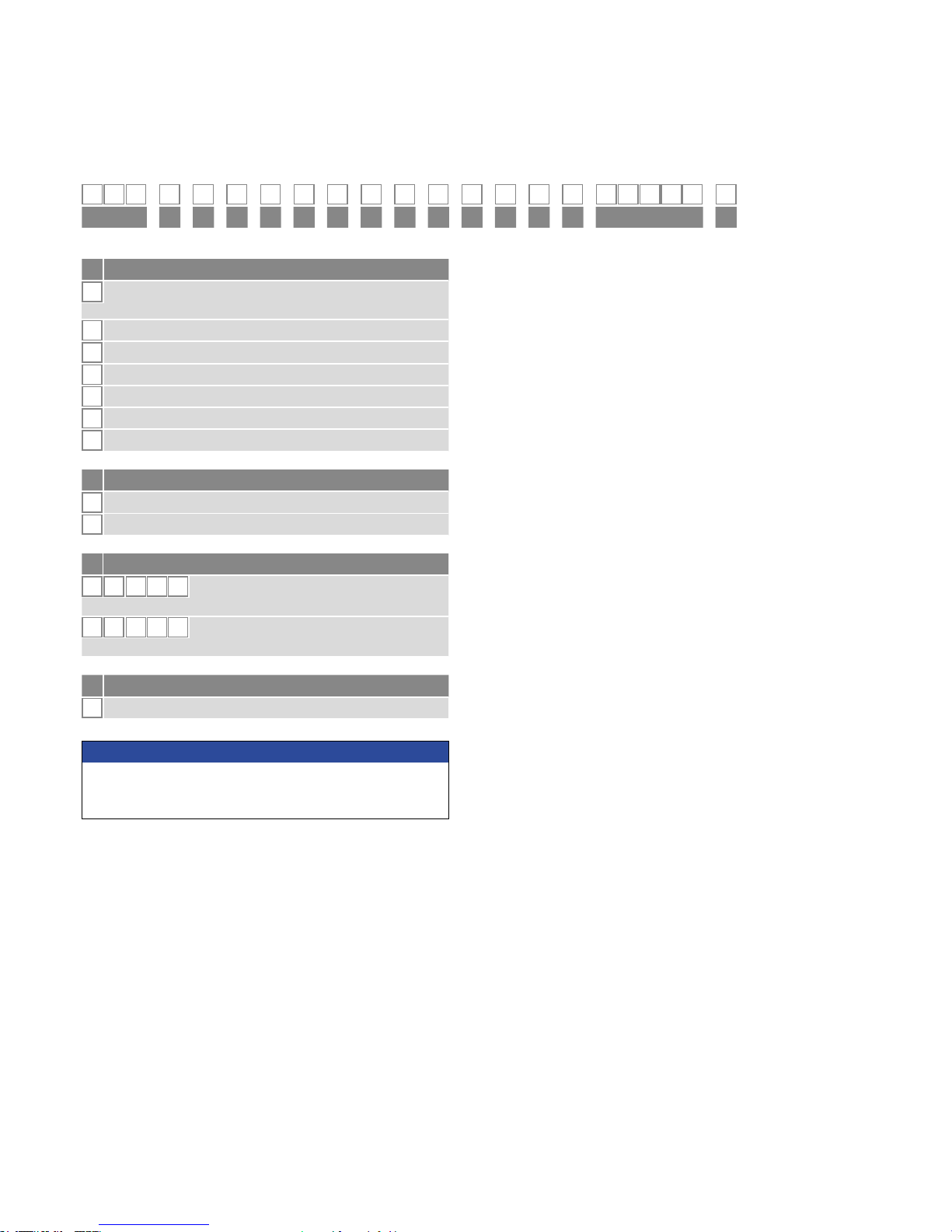
1 2 3 4 5 6 7 8 9 10 11 12 13 14 15 16 17 18 19 20 21 22
L P S
a b c d e f g h i j k l m n o p
a Sensor model
L P S
SoClean
®
Level Transmitter
b Output
M Modbus
D DDA
1 1 Loop with HART
®
2 2 Loop with HART
®
5 1 Loop with HART® and SIL 2
7 2 Loop with HART® and SIL 2 (loop 1 only)
d Electronics mounting
1 Standard
f Materials of construction (Wetted parts)*
1 316L stainless steel
2 Electropolished 316L stainless steel
e Sensor pipe
C
Sanitary T-bar, TB
D
Sanitary drain-in-place DP
E
Sanitary clean-in-place CP
F
Sanitary drain-in-place no hole, DN
c Housing type
A
NEMA housing w/cable
B
NEMA housing w/terminal
C
NEMA housing w/connector
D
Single cavity with display
E
Dual cavity with display
L
SS single cavity w/display
g Process connection type
1
NPT adjustable (¾ in. only)
2
BSPP adjustable (¾ in. only)
4
Sanitary Tri-Clamp, Welded
5
Sanitary Tri-Clamp, Adjustable
h Process connection size
A
¾ in. - NPT or BSPP only
C
1.5 in. (DN40) (* Only for for Pipe option C or F)
D
2 in. (DN50)
E
2 ½ in. (DN65)
F
3 in. (DN80)
G
4 in. (DN100)
J
6 in. (DN150)
X
None
i Number of DT‘s (Digital Thermometers)
0
None
1
One DT
5
5 DTs (Modbus or DDA)
K
Twelve DTs (Modbus only)
M
Sixteen DTs (Modbus only)
j DT‘s placement
F
Evenly spaced per API
C
Custom
X
None
*/ Contact factory for other materials
5.5 Model number identification
k Notied body
C
CEC (FMC)
E
ATEX
F
NEC (FM)
I
IEC
X
None
B
INMETRO
N
NEPSI
P
CCOE
T
TIIS
l Protection method
F Explosionproof / Flame proof (only for housing type D, E, or L)
I Intrinsically safe
X No approval
Continued on next page…
Level Plus® SoClean
®
Operation Manual
I 10 I
1 2 3 4 5 6 7 8 9 10 11 12 13 14 15 16 17 18 19 20 21 22
L P S
a b c d e f g h i j k l m n o p
m Gas group
A
Group A (not available with “C = CEC (FMC)” notied body and
“F = Flameproof/Explosion“ proof protection method)
B
Group B
C
Group C
D
Group D
3
IIC (Instrinsically Safe only)
4
IIB + H2 (Explosion Proof / Flameproof only)
X
None
n Unit of measure
M Millimeters (Metric)
U Inches (US customary)
p Special
S Standard product
o Length (no decimal spaces)
X X X X X
Rigid pipe: 305…7620 mm
(code as 00305 to 07620)
X X X X X
Rigid pipe: 12…300 in.
(code as 01200 to 30000)
NOTICE
Accessories such as floats, cables, and remote displays have to be
ordered separately. All accessories are shown in the Accessories
Catalog (551103).

Level Plus® SoClean
®
Operation Manual
I 11 I
5.6 Technical data
Level Output
Measured Variable Product level and interface level
Output Signal /Protocol Modbus RTU, DDA, Analog (4…20 mA), HART
®
Order Length
305 mm (12 in.) to 7620 mm (300 in.) (order length equals the measurement range plus the inactive
zone / contact factory for longer lengths)
Inherent Accuracy ±1 mm (0.039 in.)
Repeatability 0.001% F.S. or 0.381 mm (0.015 in.) whichever is greater (any direction)
Temperature Output
Measured Variable
Average and multipoint temperatures (Modbus, DDA)
Single point temperature (Analog, HART
®
)
Temperature Accuracy (Modbus, DDA)
±0.2 °C (0.4 °F) range −40…−20 °C (−40…−4 °F),
±0.1 °C (0.2 °F) range −20…+70 °C (−4…+158 °F),
±0.15 °C (0.3 °F) range +70…+100 °C (+158…+212 °F),
±0.5 °C (0.9 °F) range +100…+105 °C (+ 212 …221 °F)
Temperature Accuracy (Analog, HART
®
) ±0.28 °C (0.5 °F) range −40…+105 °C (−40…+221 °F)
Electronics
Input Voltage 10.5…28 VDC
Fail Safe
High, Full scale (Modbus, DDA)
Low, 3.5 mA default or High, 22.8 mA (Analog, HART
®
)
Reverse Polarity Protection Series diode
EMC
EN 61326-1, EN 61326-2-3, EN 61326-3-2, EN 61000-6-2, EN 61000-6-3, EN 61000-4-2, EN 61000-
4-3, EN 61000-4-4, EN 61000-4-5, EN 61000-4-6, EN 61000-4-8, EN 61000-4-11
Environmental
Enclosure Rating NEMA Type 4X, IP65
Humidity 0…100% relative humidity, non-condensing
Operating Temperatures
Electronics: −40…+71 °C (−40…+160 ºF)
Sensing element: −40…+125 °C (−40…+257 °F) (contact factory for specific temperature ranges)
Temperature element: −40…+105 °C (−40…+221 °F)
Vessel Pressure Rigid pipe: 69 bar (1000 psi)
Materials
Wetted parts: 316L stainless steel (contact factory for alternative materials)
Non-wetted parts: 316L stainless steel, Epoxy coated aluminum
Field Installation
Housing Dimensions Single cavity: 145 mm (5.7 in.) W × by 127 mm (5 in.) D × 109 mm (4.3 in.) H
Dual cavity: 117 mm (4.6 in.) W × by 127 mm (5 in.) D × 206 mm (8.1 in.) H
Stainless steel single cavity: 178 mm (7.1 in.) W × by 135 mm (5.3 in.) D × 153 mm (6 in.) H
NEMA Type 4X: 87 mm (3.4 in.) W × by 124 mm (4.9 in.) D × 132 mm (5.2 in.) H
Mounting
Rigid pipe Tri-Clamp, 3/4 in. Adjustable MNPT or BSPP tting
Wiring
Connections
4 wire shielded cable or twisted pair,
4570 mm (180 in.) integral cable with pigtail
Daniel Woodhead 6 pin male connector
Electrical connections
Single and dual cavity ¾ in. FNPT conduit opening, M20 for ATEX/IECEx version
NEMA Type 4X ½ in. FNPT conduit opening
Display
Measured variables Product level, interface level and temperature
Level Plus® SoClean
®
Operation Manual
I 12 I
6. Installation and mounting
6.1 Training
Warning:
When the pipe/hose of the LP-Series level transmitter is installed or
removed from the tank the release of flammable vapors will occur.
Take all necessary precaution when installing or removing the level
transmitter due to the release of flammable vapors.
Installation should only be conducted by qualified service personnel
according to IEC 60079-14 and local regulations or MTS trained
service technicians. MTS offers web based and in person training
for installation, commissioning, maintenance, and repair. MTS also
offers factory direct services for these same functions. Contact MTS to
discuss training or factory direct services before starting.
6.2 Stilling wells and guide poles
Level Plus
®
transmitters can be mounted in slotted or unslotted stilling
wells but a slotted stilling well is always preferred. Using a unslotted
stilling well will negatively affect performance of any level device as
the level in the stilling well can differ from the level in the tank. The
Level Plus
®
transmitter can also be installed to one side of the stilling
well to also allow for sampling and manual gauging from the same
opening as the automatic tank gauging. Contact technical support for
details.
Level Plus
®
transmitters do not require a stilling well for installation.
Our transmitters are installed in numerous tanks without stilling wells
with no loss in performance due to our patented flexible waveguide
and hose. A stilling well is highly recommended for agitated, turbulent,
and/or fast filling tanks.
6.3 Tools
• Channel Lock pliers
• Common head screwdriver, slotted screwdriver
• 3/4" Open End wrench
• Phillips head screwdriver, plus screwdriver
6.4 Installation steps
Caution:
It is recommended that assembly and mounting of this transmitter
should not be done alone. To ensure proper and safe assembly of
the SoClean
®
transmitter, a minimum of two (2) individuals are
recommended. Gloves are also recommended. PPE may be required
for work areas such as safety shoes, safety glasses, hard hat, and
fire resistant clothing.
1. Consult chapter 4.3 before starting.
2. Perform steps 1-10 in chapter 8.4.1 for Modbus or DDA. Perform
steps 1-9 in chapter 8.4.2 for Analog.
3. For CP end plug, remove hitch pin and install float. For DN end
plug, install float but be careful as float is not retained and will fall
off. For TB and DP end plugs, the float is already installed. Secure
the Tri-Clamp onto the mating connection on tank.
4. Tighten the Tri-Clamp to hold the transmitter in place.
5. Terminate the field wire cables noting proper wire orientation.
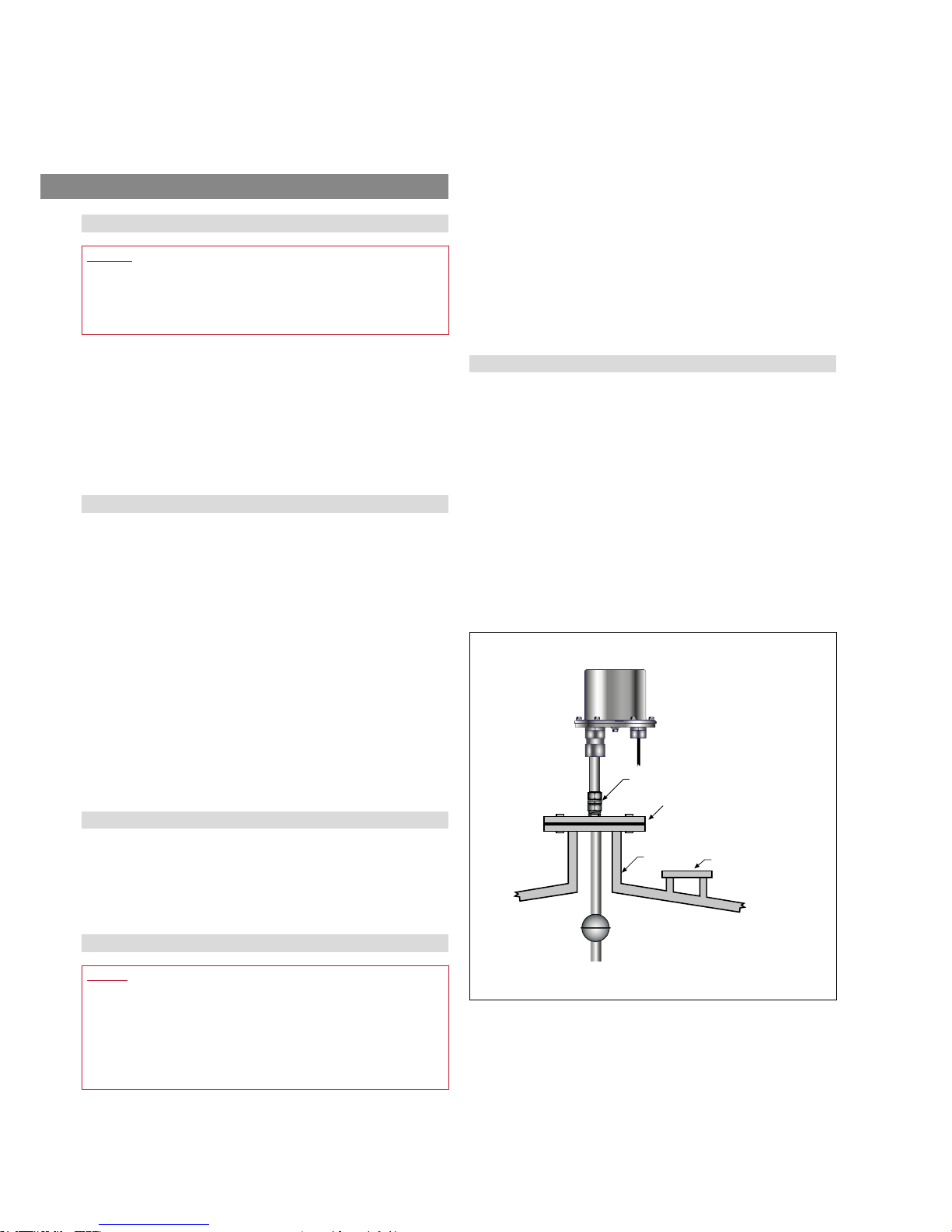
6.5 Mounting
The method of mounting the transmitter is dependent on the vessel
or tank in which it is being used, and what type of transmitter is being
mounted. There are two typical methods for mounting; threaded flange
mounting and welded flange mounting.
Threaded flange mounting
In some applications, the SoClean
®
transmitter can be mounted
directly to the tank or flange via a NPT or BSPP threaded fitting,
assuming there is a proper threaded connection available. If the float
will not fit through the flange opening when the flange is removed,
there must be some alternative means to mount the float on the
transmitter from inside the vessel; this may require an access port
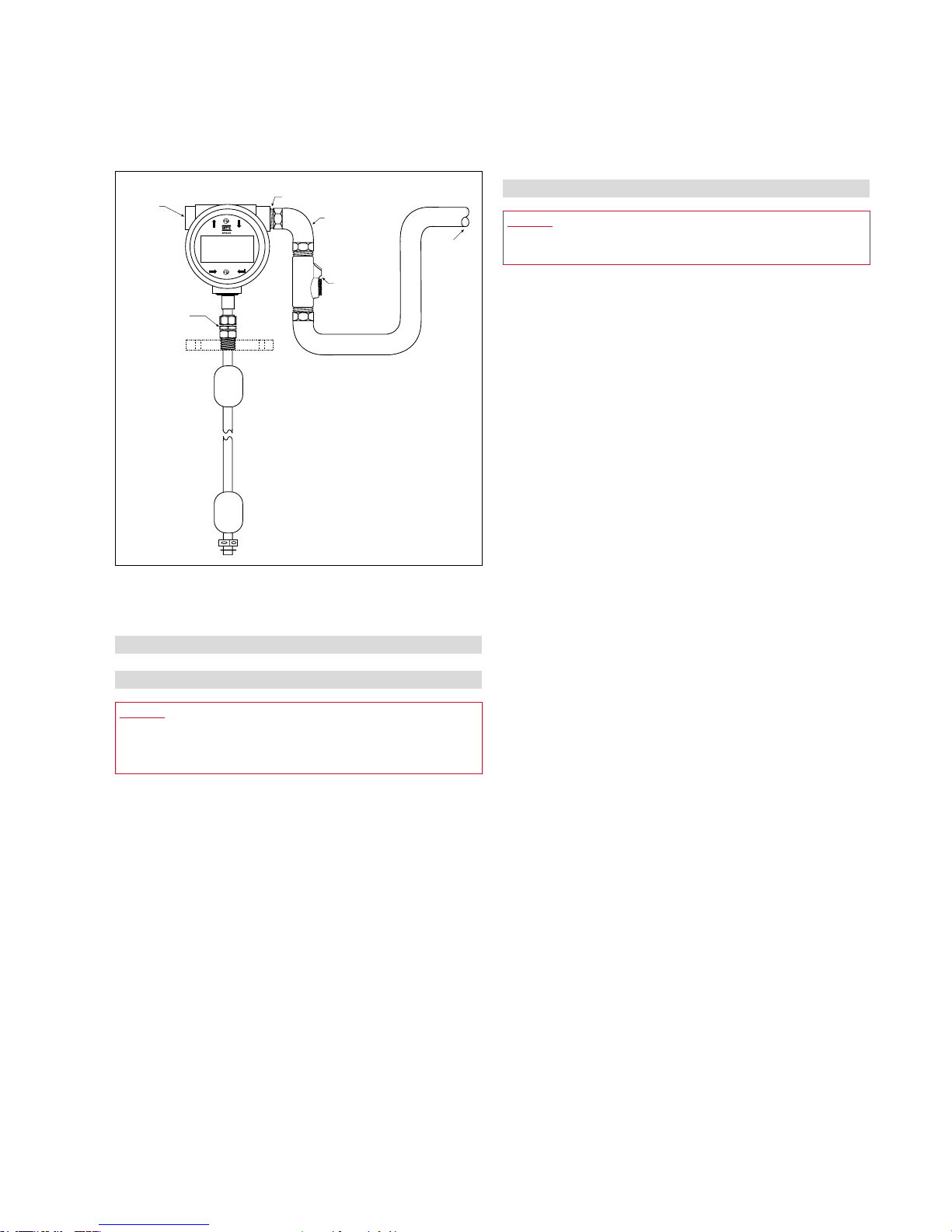
nearby the entry point of the transmitter as shown in Fig. 8.
Fig. 8: Threaded flange mounting for flexible pipe
Riser
NPT or BSPP fitting
Tank flange
(customer supplied
or ordered separately)
Float access
port
Level Plus® SoClean
®
Operation Manual
I 13 I
Tri-Clamp mounting
The SoClean
®
transmitter can also be mounted to a Tri-Clamp as
shown in Fig. 10. First, install float(s) onto the transmitter. Second,
install the float retaining hardware on the tip of the transmitter. To
complete the installation, mount the transmitter, Tri-clamp and float(s)
as a unit in to the tank.
Fig. 10: Tri-Clamp mounting for pipe
Tri-Clamp® Cap size
Inactive Zone
(See important note below)
Sanitary
Tri-Clamp
®
Cap
Sanitary
Tri-Clamp
®
Fitting
124 mm
(4.9 in.)
87mm
(3.4 in.)
132 mm
(5.2 in.)
127 mm
(5.0 in.)
305 mm (12 in.) to
7620 mm (300 in.)
7. Electrical connections
7.1 Basic information
A typical intrinsically safe connection for the Level Plus
®
SoClean®
transmitter includes protective safety barriers, a power supply and a
reading or monitoring device. Refer to Agency information in chapter
13.
A typical Explosionproof/flame proof connection for the Level Plus
®
SoClean
®
transmitter includes a power supply and a reading or
monitoring device. All cabling is in approved conduit with sealoffs
as specified by local electrical code. Refer to agency information in
chapter 13.
7.2 Safety recommendations
Be sure to:
1. Always follow applicable local and national electrical codes and
observe polarity when making electrical connections.
2. Never make electrical connections to the Tank Slayer
®
transmitter
with power turned on.
3. Make sure that no wire strands are loose or sticking out of
the terminal block connection which could short and cause a
problem.
4. Make sure that no wire strands, including shield, are in contact
with the electronic module enclosure.
5. The electronics module enclosure is grounded through internal
circuitry and is electrically isolated from the explosionproof
housing.
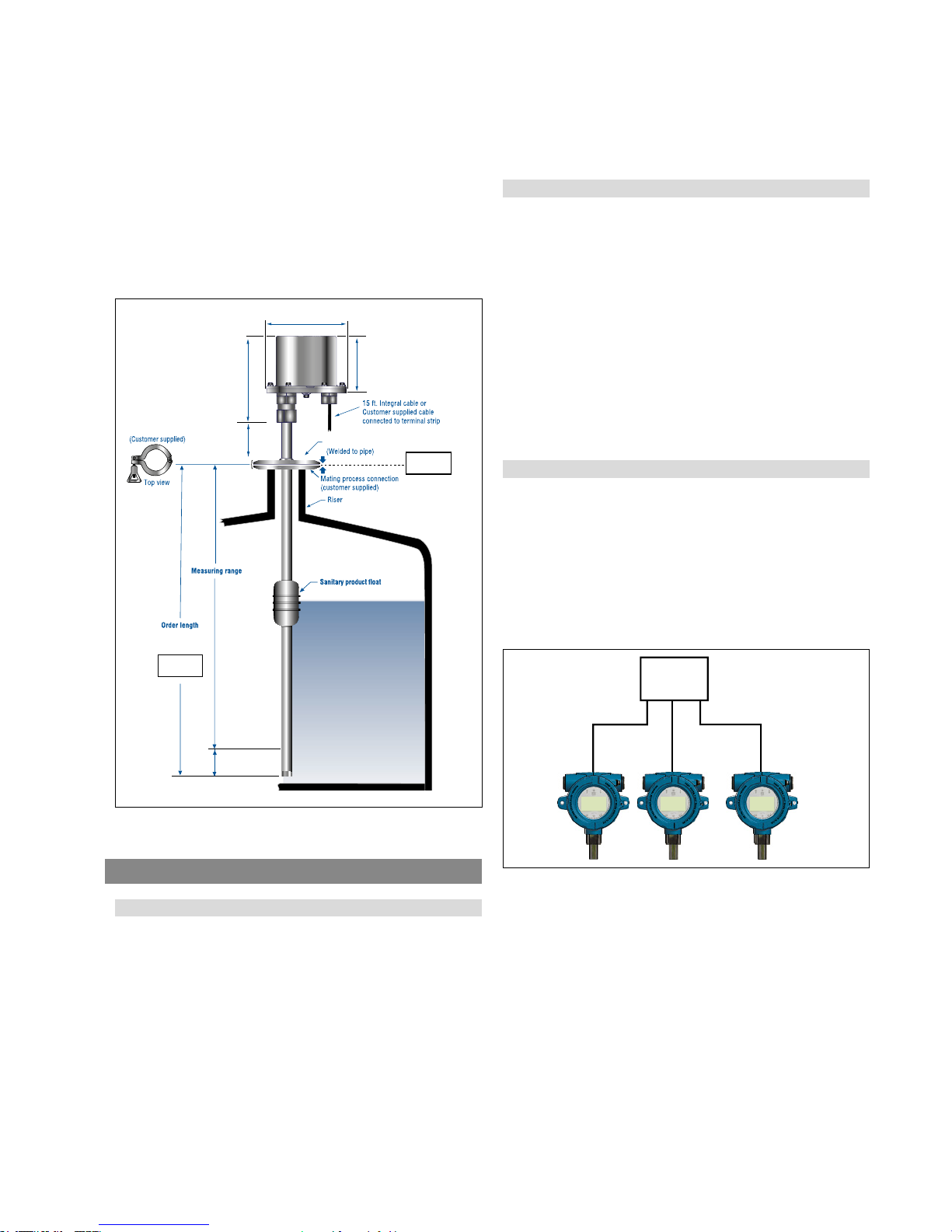
7.3 Industrial topologies
There are four topologies described and illustrated below. However,
the daisy chain topology is not recommended by MTS.
Point-to-point
The point-to-point topology consists of having only one device on the
loop as shown in Fig. 9. This topology is not usually used with a bus
network since it does not take advantage of placing multiple devices
on a loop.
PLC
Fig. 9: Point-to-point topology
Level Plus® SoClean
®
Operation Manual
I 14 I
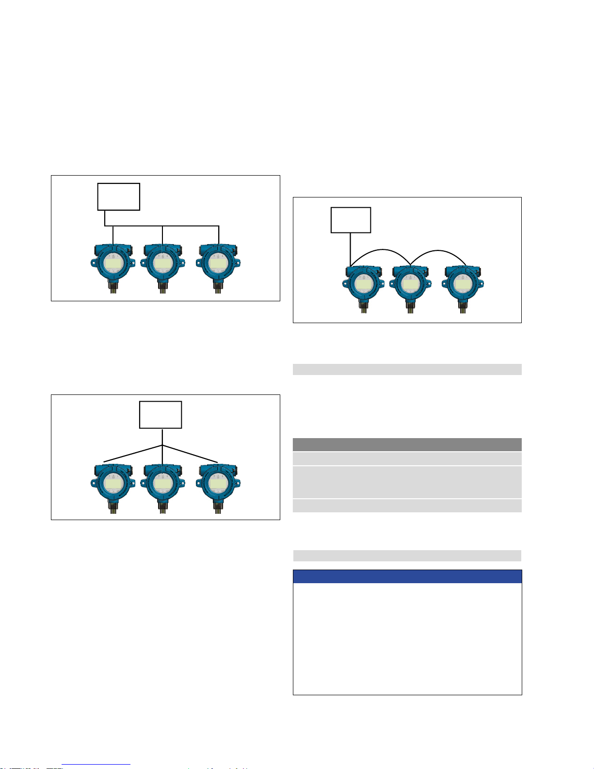
Fig. 11: Bus with spurs topology
PLC
Fig. 12: Tree topology
Fig. 13: Daisy-chain topology
Tree alignment
The tree topology is very similar to the bus with spurs topology with
the main difference of having a common junction box for all of the
transmitters as shown in Fig. 12. Bus with spurs and tree topologies
can also be used together to form a hybrid topology.
Daisy chain
The daisy-chain topology utilizes a single cable that is connected to
all of the transmitters with the cable being interconnected at each field
device. When using this topology make sure that the wiring practice
allows for one transmitter to be disconnected without disconnecting
the entire loop as shown in Fig. 13. MTS does not suggest using the
daisy-chain topology.
PLC
PLC
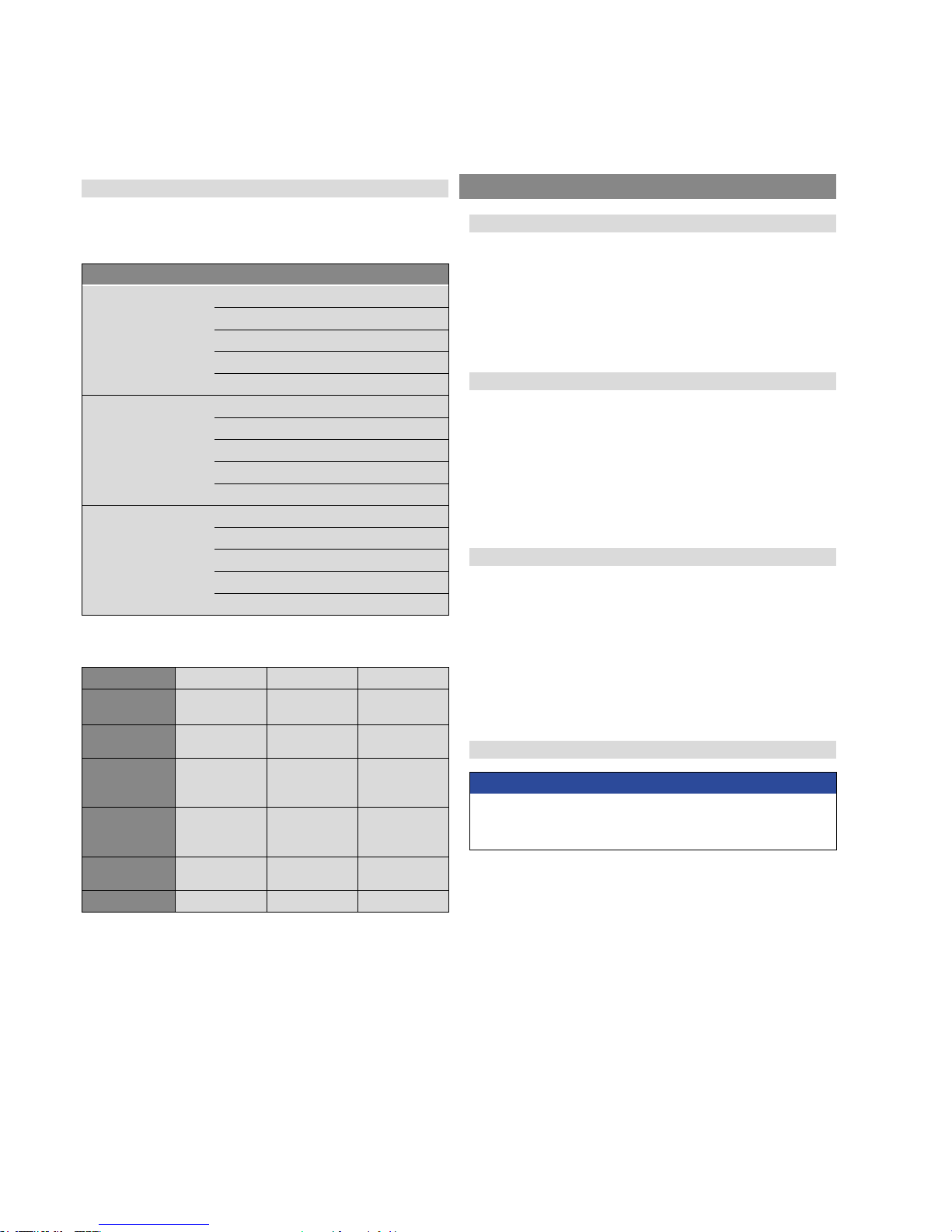
Table 2: Cable specification and parameters
7.4 Cable recommendations
Refer to ‘Table 2’ below for general requirements of cable types for the
Level Plus® SoClean® analog transmitter.
Cable specifications
7.5 Electrical conduit
Parameter Specifitcation
Minimum cable size Ø 0.51…1.6 mm (24…14 AWG)
Cable type
Single pair shielded or multiple pair with
overall shield; minimum 0.25 mm (0.010 in.)
insulation thickness
Capacitance Less than 98 pF/m (30 pF/ft)
NOTICE
1. Tighten housing cover (both front and back covers if dual cavity)
to full stop against the O-ring.
2. Do not over-tighten compression fittings.
3. Use side conduit entry only.
4. In high humidity areas, use a breather drain type conduit sealing
fitting to minimize moisture intrusion.
5. For Division Installations, an approved conduit seal is required
within 457 mm (18 in.) of the enclosure.
6. For Zone Installations, an approved conduit seal is required within
50 mm (2 in.) of the enclosure.
Bus with spurs
The bus with spurs topology has a main trunk cable that has each
device connected via its own spur at a junction box as shown in Fig.
11. The bus with spurs and tree topologies can also be used together
to form a hybrid topology.
Level Plus® SoClean
®
Operation Manual
I 15 I
Fig. 14: Electrical conduit installation
Conduit sealing fitting
NPT or BSPP Fitting
Do not over-tighten
compression fitting!
Interface float
(ordered
separately)
Product float
(ordered
separately)
View shown with
cover removed
Plugged entry
Do not use
(see notes)
3/4 NPT or M20 conduit access
Use NPT conduit fitting only!
Conduit
(flexible or rigid)
Conduit fro
m
control room
Level Plus
®
Do not remove cover with circuit energized in
hazardous locations!
Follow safe work procedures.
7.6 Grounding
7.6.1 Safety grounding
Warning:
Grounding the transmitter through a threaded conduit connection
does not meet the requirements as a grounding of the sensor for
safety.
There are two methods to provide an earth ground connection to
the earth ground of the electronics. Either method must result in a
resistance of less than 1 Ω.
• Run an earth ground through the conduit and connect directly to the
earth ground lug inside the housing.
• Run an earth ground directly to the ground lug on the outside of the
housing.
7.6.2 Shield grounding
Warning:
The shield ground does not meet the requirements as grounding of
the sensor for safety.
Immunity performance of the sensor from external sources of
surge, burst, RF, radiated emissions and other noise is dependent
on a proper ground for the shield of the communications cable.
The communications cable shield should be of a braided type and
connected to the internal ground lug of the sensor housing.
Runs in a continuous metallic conduit
When installed inside a dedicated continuous metallic conduit,
the conduit provides a level of shielding protection from external
interference and a level of ground to the sensor housing. In this case
a foil type shielded cable with a drain wire connected to the internal
ground lug may be sufficient. Sharing of the metallic conduit with
other cables will result in loss of effective shielding performance of
the communication cable and possible degradation in performance
of the sensor. In this case a braided type shielded cable connected to
the sensor internal ground lug would be recommended. In all cases
paralleling the communications cable with any noise generating cable
inside of a conduit or with noise generating cables in close proximity
to the conduit may degrade the performance of the sensor.
Runs without a conduit
In some rare applications, or where safety may not be required, a
metallic conduit may not exist. The communications cable shield
should be of a braided type and connected to the internal ground
lug of the sensor housing. Alternatively a safety approved EMC
Cable Gland can be used for grounding the shield. Contact MTS for
information before using one of these cable glands.
NEC
Undesirable currents (ground loops) is a violation of the NEC and is a
safety hazard.
Level Plus® SoClean
®
Operation Manual
I 16 I
7.7 Safety barriers
Refer to Table 3 for entity parameters and Table 4 for example safety
barriers
Entity parameters
Digital supply
(1 per LT)
Ui = 28 VDC
Ii = 100 mA
Ci = 0.0 µF
Li = O mH
Pi = 700 mW
Digital communication
(2 per LT)
Ui = 8.6 VDC
Ii = 10 mA
Ci = 0.0 µF
Li = 0.0 mH
Pi = 21.5 mW
Analog
(1 per loop)
Ui = 28 VDC
Ii = 120 mA
Ci = 0 µF
Li = 5 µH
Pi = 840 mW
Table 3: Safety barrier entity parameter references
Table 4: Safety barrier entity parameter references
Supplier STAHL STAHL STAHL
Type
9001/01-280100-101
9001/51-280110-141
9001/01-086010-101
Maximum
voltage
28 VDC 28 VDC 8.6 VDC
Maximum
current
(each channel)
100 mA 110 mA 10 mA
Maximum
power
(each channel)
700 mW 770 mW 21.5 mW
Number of
channels
1 1 1
Interface Modbus/DDA HART
®
Modbus/DDA
8. Commissioning
8.1 Training
Commissioning should only be conducted by qualified service
personnel according to IEC 60079-14 or MTS trained service
technicians and local regulations. MTS offers web based and in person
training for installation, commissioning, maintenance, and repair. MTS
also offers factory direct services for these same functions. Contact
MTS to discuss training or factory direct services before starting.
8.2 Tools
• Channel Lock pliers
• RS485 to USB Converter (MTS Part # 380114)[Modbus and DDA]
• Windows Based PC
• Linear Regulated Power Supply
• MTS Setup Software
• HART
®
to USB Converter (MTS Part # 380068)
8.3 Setup software
MTS offers Setup Software that is shipped with the level transmitter
and is also available for download from www.mtssensors.com. The
Setup Software is to be used for installation, commissioning, and
troubleshooting. For further details on how to use the setup software
consult the Modbus Interface Manual (MTS Part# 551700), the DDA
Interface Manual (MTS Part# 551701), and HART
®
Interface Manual
(MTS Part#: 551702).
8.4 Commissioning steps
NOTICE
For Additional details consult the protocol specific Modbus Interface
Manual (MTS Part #551700), DDA Interface Manual (MTS Part
#551701), and HART
®
Interface Manual (MTS Part #551702).

Level Plus® SoClean
®
Operation Manual
I 17 I
8.4.1 Modbus or DDA
1. Consult chapter 4.3 before starting.
2. Remove level transmitter from shipping container.
3. Insert pipe into float(s) making sure float(s) are in the active
range. Install product float first.
4. Connect power, RS485 to USB converter, and PC.
5. Open MTS Setup Software.
6. Establish Communication.
7. For DDA Interface – Set Address.
8. For Modbus Interface – Set Address, Enter Strap Table, Setup
Volume Correction Method.
9. Disconnect Power and Communication. Remove floats. Prepare
level transmitter for transport to the top of the tank.
10. Complete Installation in chapter 6.4.
11. Have qualified technician perform hand measurement. Enter hand
measurement into MTS Setup Software and calibrate.
12. Store all settings as backup file according to site name and tank
number.
8.4.2 HART
®
1. Consult chapter 4.3 before starting
2. Remove level transmitter from shipping container.
3. Insert pipe into float(s) making sure float(s) are in the active
range. Install product float first.
4. Connect power, HART
®
to USB converter, and PC
5. Open MTS Setup Software.
6. Establish Communication.
7. Set/Update 4 and 20 mA setpoints
8. Disconnect Power and Communication. Remove floats. Prepare
flexible level transmitter for transport to the top of the tank.
9. Complete Installation in chapter 6.4.
10. Have qualified technician perform hand measurement. Enter hand
measurement into MTS Setup Software and calibrate.
11. Store all settings as backup file according to site name and tank
number.
9. Maintenance
9.1 Training
Maintenance should only be conducted by qualified service personnel
according to IEC 60079-14 and local regulations or MTS trained
service technicians. MTS offers web based and in person training
for installation, commissioning, maintenance, and repair. MTS also
offers factory direct services for these same functions. Contact MTS to
discuss training or factory direct services before starting.
9.2 Tools
• Channel Lock pliers
• Phillips screwdriver, plus screwdriver
• Common head screwdriver, slotted screwdriver
9.3 Inspection
Below are some standard items that should be inspected on a
regular basis to make sure that the level transmitter and surrounding
environment are in operating condition.
• Hazardous Area Label is present and legible
• Hazardous Area approval is correct for installation
• There are no visible unauthorized modifications
• Electrical connections are tight
• Condition of enclosure gasket is satisfactory
• No water ingress (white powder)
• No obvious damage to cable
• Sealing of conduit or cable gland is satisfactory
• Earth ground is satisfactory
• Single or Dual Cavity Enclosure threads are not damaged
• Housing and O-ring are not damaged or cracked
• No corrosion on visible parts
• Printed circuit boards are clean and undamaged
9.4 Preventative maintenance
Level Plus
®
level transmitters do not typically require preventative
maintenance but may require preventative maintenance dependent
on the application. For general purpose applications where there is
no potential for buildup on the pipe and/or float there is no need for
preventative maintenance but routine inspection is still suggested. For
severe service applications where there is potential for buildup on the
pipe and/or float then preventative maintenance is required.
Level Plus® SoClean
®
Operation Manual
I 18 I
9.4.1 General purpose applications
9.4.1.1
Perform Inspection suggested in chapter 9.3.
9.4.1.2
No additional preventative maintenance is necessary. Preventative
maintenance suggested for Severe Service Applications may be
performed.
9.4.2 Severe Service Applications
9.4.2.1
Perform Inspection suggested in chapter 9.3.
9.4.2.2
Disconnect Power.
9.4.2.3
Disconnect process connection from tank. Remove pipe from
tank.
NOTE
It is best to clean the pipe as it is removed from the tank to minimize
the amount of product that is removed from the tank. The user
should take caution and abide by all regulations so that product is
not spilled and the environment is not contaminated.
9.4.2.4
When the bottom of the pipe is reached inspect the floats.
9.4.2.4.1
If the floats are highly contaminated then remove the assembly from
the tank and remove the floats from the pipe. This is not possible with
TB and DP end plugs.
9.4.2.4.2
If the floats are slightly contaminated then clean the floats without
removing the floats from the pipe.
9.4.2.5
Replace pipe and floats in tank.
9.4.2.6
Connect process connection to tank.
9.4.2.7
Connect Power.
9.4.2.8
The process should be carried out regularly until a consistent pattern
has been established as to how long the intervals between cleanings
should be.
10. Repair
10.1 RMA policy
Important:
Contact Technical Support or Customer Service for assistance if
you suspect that the transmitter is not working correctly. Technical
support can assist you with troubleshooting, part replacement, and
Returned Material Authorization (RMA) information if required.
All Level Plus® transmitters come with a two year limited warranty
from the factory shipment date. A Return Materials Authorization
(RMA) number is required and must accompany any transmitter
returns. Any unit that was used in a process must be properly cleaned
in accordance with OSHA standards, before it is returned to the
factory. A Material Safety Data Sheet (MSDS) must also accompany
the transmitter that was used in any process.
10.2 Training
Repair should only be conducted by qualified service personnel
according to IEC 60079-14 and local regulations or MTS trained
service technicians. MTS offers web based and in person training
for installation, commissioning, maintenance, and repair. MTS also
offers factory direct services for these same functions. Contact MTS to
discuss training or factory direct services before starting.
10.3 Tools
• Channel Lock pliers
• Phillips head screwdriver, plus screwdriver
• Common head screwdriver, slotted screwdriver
• RS485 to USB Conververter (MTS Part # 380114)
[Modbus and DDA]
• Windows Based PC
• Linear Regulated Power Supply
• HART
®
to USB Converter (MTS Part # 380068)[HART®]
 Loading...