

Page 1

SENSORS
Level Plus ®
Liquid-Level Sensors
M-Series
Model MG
Digital Output
Transmitter Electronics Replacement Guide
M-Series Model MG
digital transmitter
551104 A
Contents
Guide overview
Software and hardware requirements
Technical support and shipping information
Notices used in this guide
Related publications
Before you begin
Software installation and conguration; Modbus and DDA
Transmitter electronics replacement procedures
Installing current parameters
Guide overview
This guide contains software setup and digital component replacement procedures for the MTS M-Series Model MG digital transmitter
(gauge). Software setup screens shown in this guide are Modbus
examples. If you are installing DDA setup software, your setup screens
will be similar.
Software and hardware requirements
MTS Part Numbers:
625051 - M-Series PC Setup Modbus Software CD and RS-485 to
RS-232 Adapter
625052 - M-Series Digital PC Setup Modbus Software CD
380075 - RS-485 to RS-232 Adapter
625053 - M-Series Digital PC Setup (DDA)
Technical support and shipping information
The M-Series transmitter design is modular in nature. The electronics
can be replaced in the field without on-site support of the MTS Service
Department.
Ordering information and software updates:
You can get the latest ordering information and software updates by
using the World Wide Web. Go to www.mtssensors.com.
Technical support
Phone: 800-633-7609
E-mail: [email protected]
Shipping address
MTS Systems Corporation
Sensors Division
3001 Sheldon Drive
Cary, North Carolina 27513
Notices used in this guide
Notes
These notices provide important tips, guidance, or advice.
Caution
These notices indicate situations that can be potentially hazardous to
you. A Caution notice is placed just before a description of a potentially
hazardous procedure, step, or situation.
Attention
These notices indicate possible damage to devices or data. An
Attention notice is placed before the instruction or situation in which
damage could occur.
Always follow applicable local and national electrical codes and
observe polarity when making electrical connections. Do not remove
cover or make electrical connections to the M-Series transmitter with
power turned on. Make sure that no wire strands are loose or sticking
out of the terminal block connection which could short and cause a
problem.
Related publications
The following publications are available in Adobe Acrobat Portable
Document Format (PDF) at http://www.mtssensors.com.
550731 - Installation sheet, M-Series Electronics Module
550784 - Product Specification, Level Plus M-Series Digital
550537 - Product Specification, Level Plus M-Series Floats and
Accessories
All specifications are subject to change. Contact MTS for specifications that are critical to
your application. Go to www.mtssensors.com for the latest support documentation.
Page 2
Before you begin
Before replacing your digital transmitter electronics, make sure that it
is programmed with the transmitter data restore file you created after
initial installation and calibration of your transmitter.
Note:
Each transmitter requires its own restore file.
To install the transmitter setup software, go to the section titled •
“Software installation and configuration; Modbus and DDA”.
To create a restore file, go to the section titled “• Create the transmit-
ter data restore file”.
If your transmitter electronics PCB is already programmed and you •
have a data restore file, go to the section titled “Replacing your
transmitter electronics PCB”.
Software installation and configuration; Modbus and DDA
Obtain the setup software that shipped with your transmitter or go to
www.mtssensors.com and download the latest Modbus or DDA setup
software from the MTS software Vault. You will be asked to register
for a login and password to enter the Vault portal. From the Vault, do
the following:
For Modbus configuration, download Modbus_*.zip
For DDA configuration, download DDA_*.zip
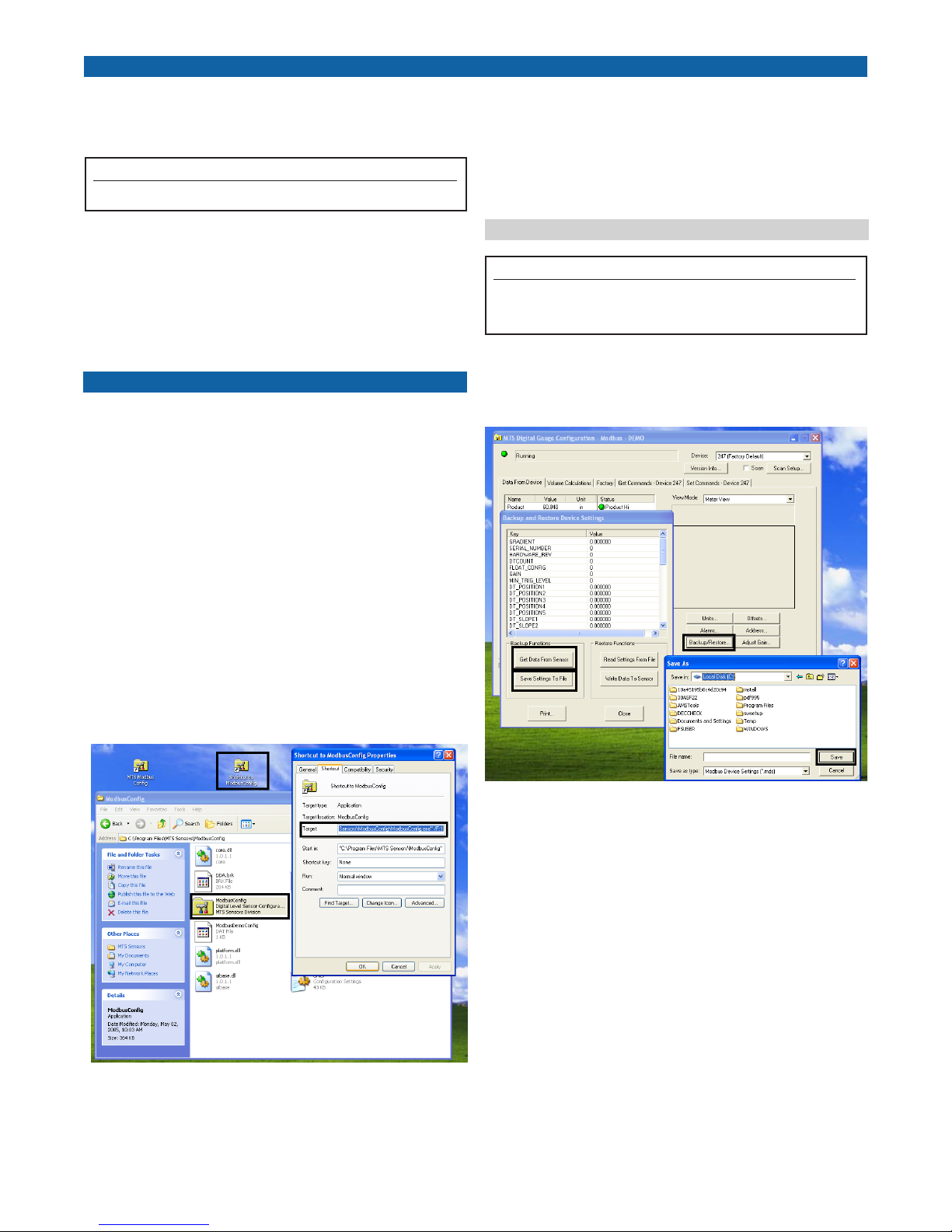
In the “Target” entry box at the end of the path string, type Spacebar/F:1.
The string should resemble one of the following:
“C:\ProgramFiles\MTSSensors\ModbusCong\ModbusCong.exe”/F:1
“C:\ProgramFiles\MTSSensors\DDACong\DDACong.exe”/F:1
Continue with “4. Create the transmitter data restore file”.
Create the transmitter data restore file
Note:
Each transmitter requires its own restore file. Your transmitter must be
installed properly and calibrated before you create the data restore file.
Perform the following steps to create a transmitter data restore file:
Click the program file icon to launch the configuration setup 1.
software. The setup “Configuration” window opens (Figure 2).
Perform the following steps to extract and install the setup software:
Locate and double-click the appropriate 1. protocol_*.zip file. Extract
the program folder into C:\ProgramFiles\ and double-click the *.exe
file to install the program.
Create shortcut and Enable factory mode:2. Go to C:\ProgramFiles\MTS
Sensors\ and right click the program configuration folder. Drag the
folder to your desktop.
Right click the Configuration folder shortcut icon, select “3. Proper-
ties”. The shortcut properties dialog box opens (Figure 1).
Shortcut creation and Target entryFigure 2.
Connect the transmitter. If the transmitter is connected proper-2.
ly, you will see five new tab selections at the top of the window.
perform the following:
Click the “a. Data from Device” tab, a new window opens.
Click the “b. Backup/Restore” button. a new window opens.
Click the “c. Get Data from Sensor” button, then select the
“ Save settings to file” button.
Type in a filename such as d. ModbusRestore or DDARestore
and path that you can easily locate. then, click “Save”
Shortcut creation and Target entryFigure 1.
2
MTS SensorsM-Series Model MG Digital Gauge, Transmitter Electronics - Replacement Guide 551104 A
Page 3
Transmitter electronics replacement procedure
Complete the following steps to remove and replace your transmitter
electronics board after you have successfully created a data restore
file.
Caution:
Ensure that all power is disconnected and that all lockout procedure(s) are
followed prior to opening the transmitter instrument housing.
Removing the transmitter electronics boards
Remove any dirt, debris, or liquid from the top of the instrument 1.
enclosure.
Remove the instrument housing cover.2.
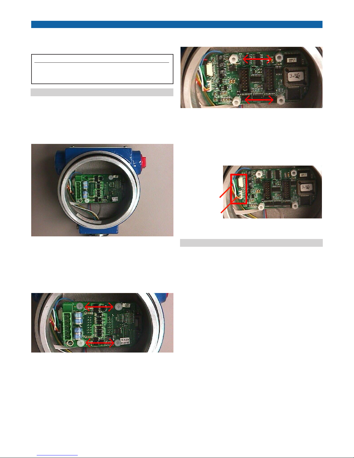
Remove wired connector (replacement included if needed) from PC 3.
board terminal block (Figure 3).
Unscrew four standoffs and remove bottom board (5. Figure 5).
Bottom electronics board standoffs locationsFigure 5.
Disconnect the white sensing element (SE) 6-pin connector from 6.
the bottom board (pull straight out) and remove the white DT ribbon
cable connector with a small green connector card if present (slide
wing outward and pull connector out parallel to the PCB sideways)
(Figure 6).
DT connector
with green board
Transmitter electronics top board with connector removedFigure 3.
Remove the existing transmitter electronics by unscrewing the four 4.
retaining screws and removing the (top) board. Note the orientation
of boards housing before removal to aid in installation of replacement boards (Figure 4).
Top electronics board retaining screw locationsFigure 4.
SE connector
SE and DT connector locationsFigure 6.
Replacing the transmitter electronics boards
Use the same procedure and adhere to the same cautions noted in the
board removal process when reinstalling boards. Install the boards in
the following order:
Reconnect the sensing element (SE) connector and DT connector 1.
(when available). Before you reconnect the DT to the board, verify
that the gold DT connector pins are facing down. Push wing back in
lock the DT cable.
Install the new base board (round edges) with four standoffs 2.
(replacement standoffs included).
Install top board and secure with four screws (replacement screws 3.
are included with kit). Verify that the orientation of the boards
are such that the connectors are all located on the same side as in
(Figure 4).
Plug the wired connector into the PC board terminal block.4.
Reattach the transmitter instrument housing cover.5.
MTS Sensors M-Series Model MG Digital Gauge, Transmitter Electronics - Replacement Guide 551104 A
3
Page 4
Removing and replacing the ME/SE
Attention:
If PC boards are in the housing, be sure you disconnect the SE and
DT cables first. When removing the pipe from the housing, damage
to the DT cable SE connections may occur if proper care is not taken
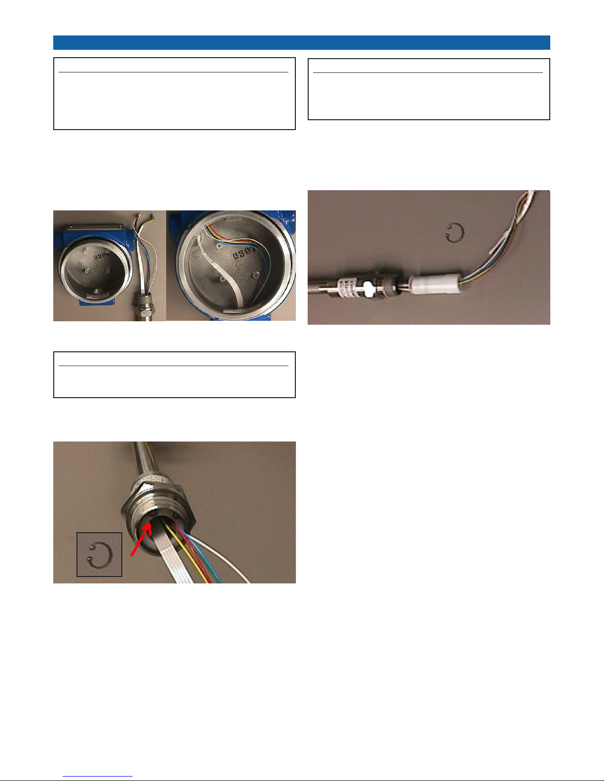
(Figure 7).
Remove the SE and DT cable connections first, See Removing the 1.
transmitter electronics boards.
Slowly unscrew the pipe from the housing. Be aware of possible 2.
damage to the DT and SE connectors when performing this step
(Figure 7).
SE and DT connector locationsFigure 7.
Attention:
Damage to the SE and DT can occur when removing the plastic base
cartridge and heat shrink tubing from the SE (Figure 8).
Using e-clip or needle nose pliers, remove the retaining clip from 3.
the inside of the pipe (Figure 8).
Attention:
To avoid component damage, removing the SE with needle nose pliers is
required. Please note that the SE can not be bent in less than a 2 foot radius
(Figure 9).
Using needle nose pliers, gently pull the SE cable assembly out of 4.
the pipe. Remove the white base cartridge from the SE. To avoid
damaging the SE, do not bend the SE in less than a 2 ft. radius
(Figure 9).
Removing the SE cable assemblyFigure 9.
Locate and open the • Gradient Off tag which is attached to the new
SE. Record the gradient information and place it in a safe place. The
Gradient value will be entered into the configuration software Factory tab window after installation (Step 5 in next section).
Remove the black rubber plug from the end of the new SE.•
Install the SE. There are two methods you can use to install the 5.
SE:
Roll the SE off the spool and directly into the pipe.•
Uncoil the SE and gently feed it into the pipe by hand. •
Light pressure and twisting may be required to install the SE into
the pipe. If the SE is bent or kinked, functionality and or breakage
will occur which will render the SE unrepairable.
Secure the SE with the retaining clip you removed in step 2 and 6.
reconnect the pipe to the instrument housing. Continue with
“Replacing the transmitter electronics boards”.
Removing the retaining clip from inside of the pipe assemblyFigure 8.
4
MTS SensorsM-Series Model MG Digital Gauge, Transmitter Electronics - Replacement Guide 551104 A
Page 5
Installing current parameters
Setting new gradient value and board parameters
Your new boards must be programmed before use. Follow the steps
below to program your new boards:
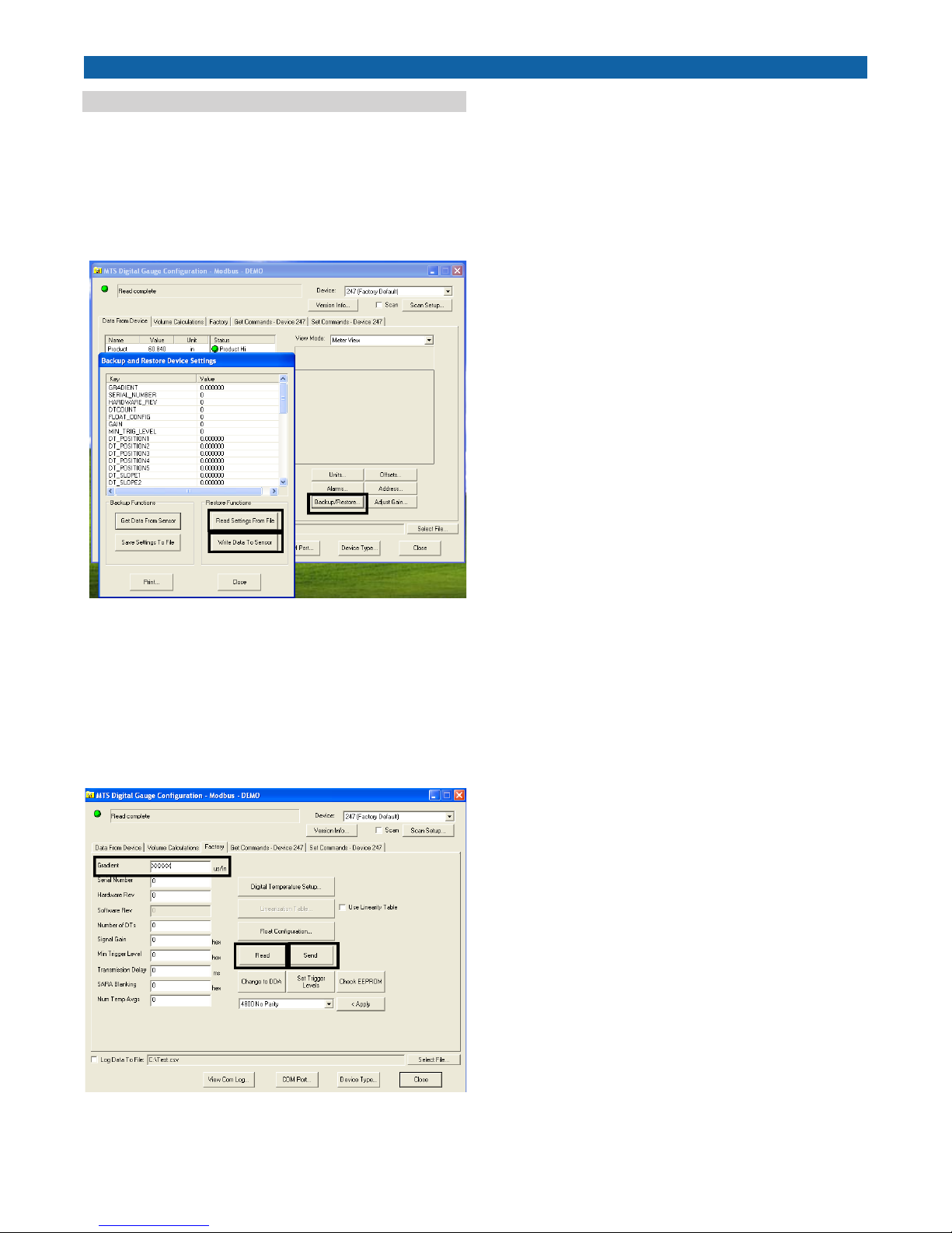
Launch your setup software and connect to the transmitter. Click 1.
the “Data from Device” tab, then click the “Backup/Restore” button.
The “Backup and Restore Device Settings” window opens (Figure
10).
Click “5. Read”.
Click the “6. Volume” tab. The Volume tab window opens. Click ”Strap
table”.
Click “7. Read from Table”. Then, click “Write data to sensor”.
You will be prompted for a password. The password is “8. becareful”.
Data from Device window; Backup and restore settings.Figure 10.
Click the “2. Read Settings from file” button. Then, select your previously saved data restore file.
Click the “3. Write Data to Sensor” button, Click “Yes”, Click “OK” and
“Close”.
Click the “4. Factory” tab. The Factory Tab window opens. Type the
Gradient value you recorded from the Gradient Off Tag (Figure 11).
new settings
Factory window; Entering the new gradient value and reading Figure 11.
MTS Sensors M-Series Model MG Digital Gauge, Transmitter Electronics - Replacement Guide 551104 A
5
Page 6
SENSORS
MTS, Temposonics and Level Plus are registered trademarks of MTS Systems Corporation.
All other trademarks are the property of their respective owners.
All Temposonics sensors are covered by US patent number 5,545,984. Additional patents are pending.
Printed in USA. Copyright © 2007 MTS Systems Corporation. All Rights Reserved in all media.
Part Number: 11-07 551104 Revision A
UNITED STATES
MTS Systems Corporation
Sensors Division
3001 Sheldon Drive
Cary, NC 27513
Tel: (800) 457-6620
Fax: (919) 677-2545
(800) 943-1145
www.mtssensors.com
[email protected]
GERMANY
MTS Sensor Technologie
GmbH & Co. KG
Auf dem Schüffel 9
D - 58513 Lüdenscheid
Tel: +49 / 23 51 / 95 87-0
Fax: +49 / 23 51 / 56 491
www.mtssensor.de
[email protected]
JAPAN
MTS Sensors Technology
Corporation
Ushikubo Bldg.
737 Aihara-cho, Machida-shi
Tokyo 194-0211, Japan
Tel: +81 (42) 775 / 3838
Fax: +81 (42) 775 / 5516
www.mtssensor.co.jp
[email protected]
 Loading...