

Page 1

Level Plus
®
Liquid-Level Sensors
With Temposonics® Technology
M-Series Model USTDII
Digital Transmitter
Brief Operation Manual For Safe Use
Document Part Number
551412 Revision A
Page 2

Page 3

UNITED STATES
Model USTDII Brief Operation Manual for Safe Use
Contact Information
GENERAL:
Tel: +1-919-677-0100
Fax: +1-919-677-2343
E-mail: [email protected]
http://www.mtssensors.com
MAILING AND SHIPPING ADDRESS:
MTS Systems Corporation
Sensors Division
3001 Sheldon Drive
Cary, North Carolina, 27513, USA
CUSTOMER SERVICE:
Tel: +1-800-457-6620
Fax: +1-800-498-4442
E-mail: [email protected]
TECHNICAL SUPPORT AND APPLICATIONS:
24 Hour Emergency Technical Support
Tel: +1-800-633-7609
e-mail: [email protected]
GERMANY
GENERAL:
Tel.: +49-2351-9587-0
Fax: +49-2351-56491
e-mail: [email protected]
http://www.mtssensor.de
OFFICE HOURS (EST):
Monday - Thursday: 8:00 a.m. to 5:00 p.m.
Friday: 8:00 a.m. to 4:00 p.m.
REMITTANCE ADDRESS:
MTS Systems Corporation
Sensors Division
NW 5872
P.O. Box 1450
Minneapolis, MN, 55486-5872
TERMS & CONDITIONS:
The parties expressly agree that the purchase and use of Material and/
or Services from MTS Sensors Division are subject to MTS’ Terms and
Conditions, in effect as of the date of this document, which are located
at http://www.mtssensors.com/about/terms-and-conditions/index.
html and are incorporated by reference into this and any ensuing
contract. Printed Terms and Conditions can be provided upon request
by e-mailing [email protected] or if you prefer, go to http://www.
mtssensors.com/index and click the Terms and Conditions link on
the page footer to download the PDF.
Contact
Information
MAILING AND SHIPPING ADDRESS:
MTS Sensor Technologie, GmbH & Co. KG
Auf dem Schüffel 9
D - 58513 Lüdenscheid, Germany
TECHNICAL SUPPORT AND APPLICATIONS:
Tel.: +49-2351-9587-0
e-mail: [email protected]
http://www.mtssensor.de
JAPAN
GENERAL:
Tel.: +81-42-775-3838
Fax: +81-42-775-5516
e-mail: [email protected]
http://www.mtssensor.co.jp
MAILING AND SHIPPING ADDRESS:
MTS Sensors Technology Corporation
737 Aihara-cho, Machida-shi
Tokyo 194-0211, Japan
TECHNICAL SUPPORT AND APPLICATIONS:
Tel.: +81-42-775-3838
Fax: +81-42-775-5512
MTS Sensors
i
Level Plus® Liquid-Level Sensors - M-Series Model USTDII Digital Transmitter
Brief Operation Manual for Safe Use, Document Number: 551412 Revision A, 04/13 (US)
Page 4

Model USTDII Brief Operation Manual for Safe Use
Table of Contents
Contact information
United States .................................................................................. i
Germany .........................................................................................i
Japan ..............................................................................................i
Safety Instructions
Intended Use ....................................................................................1
Installation, commissioning and operation ......................................1
Special conditions for use in explosion-hazardous areas .................1
Model number identification
Model number configuration ......................................................... 2
Marking .......................................................................................... 3
Entity parameters ........................................................................... 3
Basic wiring
IS Installation ...................................................................................4
Wiring connections ......................................................................... 5
Safety barrier examples ................................................................. 6
Accessories
Floats ............................................................................................. 7
Table of
Contents
Agency Information
EC declaration of conformity .......................................................... 8
Level Plus® Liquid-Level Sensors - M-Series Model USTDII Digital Transmitter
Brief Operation Manual for Safe Use, Document Number: 551412 Revision A, 04/13 (US)
ii
MTS Sensors
Page 5

Model USTDII Brief Operation Manual for Safe Use
Safety Instructions
Safety instructions
The Brief Operation Manual for Safe Use contains safety instructions. For further information do consult the Operation and Installation Manual,
document no.: 550980, available on the Level Product CD, part no.: 550766 supplied with your level transmitter or cost free download at www.
mtssensors.com .
INTENDED USE
The Level Plus® Model USTDII liquid level transmitter is used for continuous measurement of product level, interface level, and/or temperature
of liquids in containers in hazardous areas.
INSTALLATION, COMMISSIONING AND OPERATION
• The liquid level transmitter may only be installed, connected, operated and maintained by trained technical personnel. The technical
personnel must strictly adhere to the Operating Instructions, prevailing standards, legal regulations and certificates (depending on
application).
• If the Brief Operating Manual for Safe Use does not provide sufficient information, you must read the Operation and Installation
Manual. There, you can find detailed information on the device.
• The operator may only perform direct replacement of like components manufactured by MTS that are explicitly permitted in the
Operating Instructions.
• Do not operate damaged products and secure them against unintentional commissioning. Mark the damaged product as being
defective.
• If faults cannot be rectified, the products must be taken out of service and secured against unintentional commissioning.
• The product is designed to meet state-of-the-art safety requirements, has been tested and left the factory in a condition in which it
is safe to operate. Relevant regulations and European standards have been observed.
• As the user, you are responsible for complying with the following safety conditions:
- Installation instructions
- Local prevailing standards and regulations
• Only use the product according to its specification.
Safety
Instructions
SPECIAL CONDITIONS FOR USE IN EXPLOSION-HAZARDOUS AREAS
• Model USTDII sensors may only be connected to certified intrinsically safe circuits (Ex ia or Ex ib).
• The electronics housing is to be installed in zone 1 (category 2G, EPL Gb}. The sensor pipe/hose may be installed in zone 0
(category 1, EPL Ga} if not restricted below.
• Equipotential bonding shall be installed inside and outside the hazardous area along the cable for supply and data.
• Float usage:
- Metallic floats may only be used if they have a weight offset (asymmetric weight distribution).
- Metallic floats on non-metallic pipes may not be used.
- Aluminum floats may not be used.
• Plastic floats may only be installed in hazardous areas which require apparatus of category 1G (for zone 0} with explosion group IIA.
Plastic floats may not be used on non-metallic pipes.
• Sensors of type USTDII with fill tube hanger (inside the tank) are not ATEX approved for hazardous areas.
MTS Sensors
Level Plus® Liquid-Level Sensors - M-Series Model USTDII Digital Transmitter
1
Brief Operation Manual for Safe Use, Document Number: 551412 Revision A, 04/13 (US)
Page 6
Model USTDII Brief Operation Manual for Safe Use
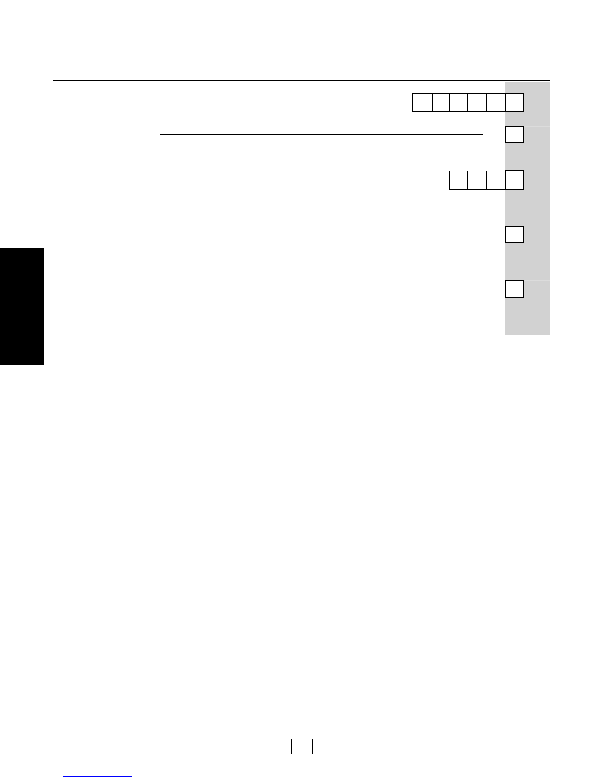
Model Number Identification
Model number configuration
TRANSMITTER MODEL =
M-Series Model USTDII liquid-level transmitter
UNIT OF MEASURE
M = Metric (millimeters)
U = US Customary (inches)
TRANSMITTER ORDER LENGTH =
Length Code
Millimeters = XXXX (737 mm to 3785 mm)
Inches = 0XXX (29 in. to 149 in.)
MOUNTING AND CATEGORY OF APPARATUS
H = Fill tube mounting (hanger with centering spacers) FM Approved
A = Flange mounting (¾ in. MNPT adjustable fitting) FM Approved
6 = Flange mounting (¾ in. MNPT adjustable fitting) ATEX Approved
MOUNTING TYPE
S = Standard product without cable (FM Approved)
9 = Standard product without cable (ATEX Approved)
7 = Cable gland and integral blue cable (ATEX Approved)
Identification
Model Number
STANDARD FEATURES
Five DT's, evenly spaced
Data output format (USTD type)
U S T D I I
= 7
= 12
= 13
1 - 6
8 - 11
USTDII CABLE ASSEMBLY OPTION
Description Part number
5 m straight connector cable (ATEX) 402486
2 m straight connector cable (FM) 530049
2 m 90° connector cable (FM) 370481
Level Plus® Liquid-Level Sensors - M-Series Model USTDII Digital Transmitter
Brief Operation Manual for Safe Use, Document Number: 551412 Revision A, 04/13 (US) 2
MTS Sensors
Page 7
Model USTDII Brief Operation Manual for Safe Use
Marking & Entity Parameters
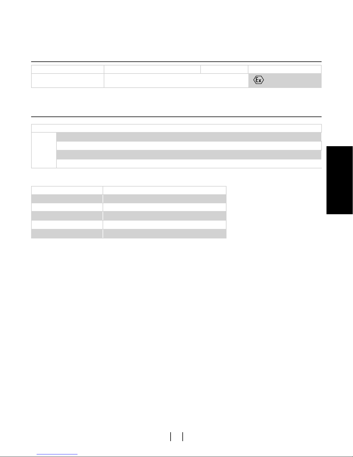
Marking
Model Mounting and category of apparatus (12) Mounting type (13) ATEX Marking
USTDII 6 7, 9
Table 1. Approval marking
Entity Parameters
Entity parameters
ATEX Ui = 28 Vdc
∑li = 200 mA
Ci = Negligibly low
Li = Negligibly low
Table 2. USTDII entity parameters
Total power consumption ∑Pi Ambient temperature at the electronics
1.3 W -20 to +40 °C (electronics)
1.2 W -20 to +60 °C (electronics)
1.0 W -20 to +80 °C (electronics, functionality up to 71 °C)
- -40 to +125 °C (sensing element)
- -40 to 105 °C (temperature sensor)
Table 3. Power and ambient temperature ranges
II 1/2 G EEx ia IIB T4
Identification
Model Number
MTS Sensors
Level Plus® Liquid-Level Sensors - M-Series Model USTDII Digital Transmitter
Brief Operation Manual for Safe Use, Document Number: 551412 Revision A, 04/13 (US)3
Page 8
0.22 mm2 OR HEAVIER
TWISTED PAIR CABLE
WITH SHIELD
SEE NOTE 2
0.22 mm
2
OR HEAVIER
TWISTED PAIR CABLE
WITH SHIELD
SEE NOTE 3
RX/TX−
RX/TX+
24 Vdc COMMON
+24 Vdc
TRANS. PROT.
SEE NOTE 6
TANKSIDE
EARTH
GROUND
HAZARDOUS LOCATION ( II 1/2 G resp II 2 G EEx ia IIB T4 resp EEx ia IIA T4)
SAFETY
BARRIER
SEE NOTE 1
24-26 Vdc +
COMMON −
SAFETY
BARRIER
SEE NOTE 1
SAFETY
BARRIER
SEE NOTE 1
EARTH GROUND
(SEE NOTE 4)
RX/TX +
RX/TX−
EARTH GROUND
(SEE NOTE 4)
GROUND
NON HAZARDOUS
AREA
NON HAZARDOUS
LOCATION
Model USTDII Brief Operation Manual for Safe Use
Basic Wiring
IS Installation
Basic Wiring
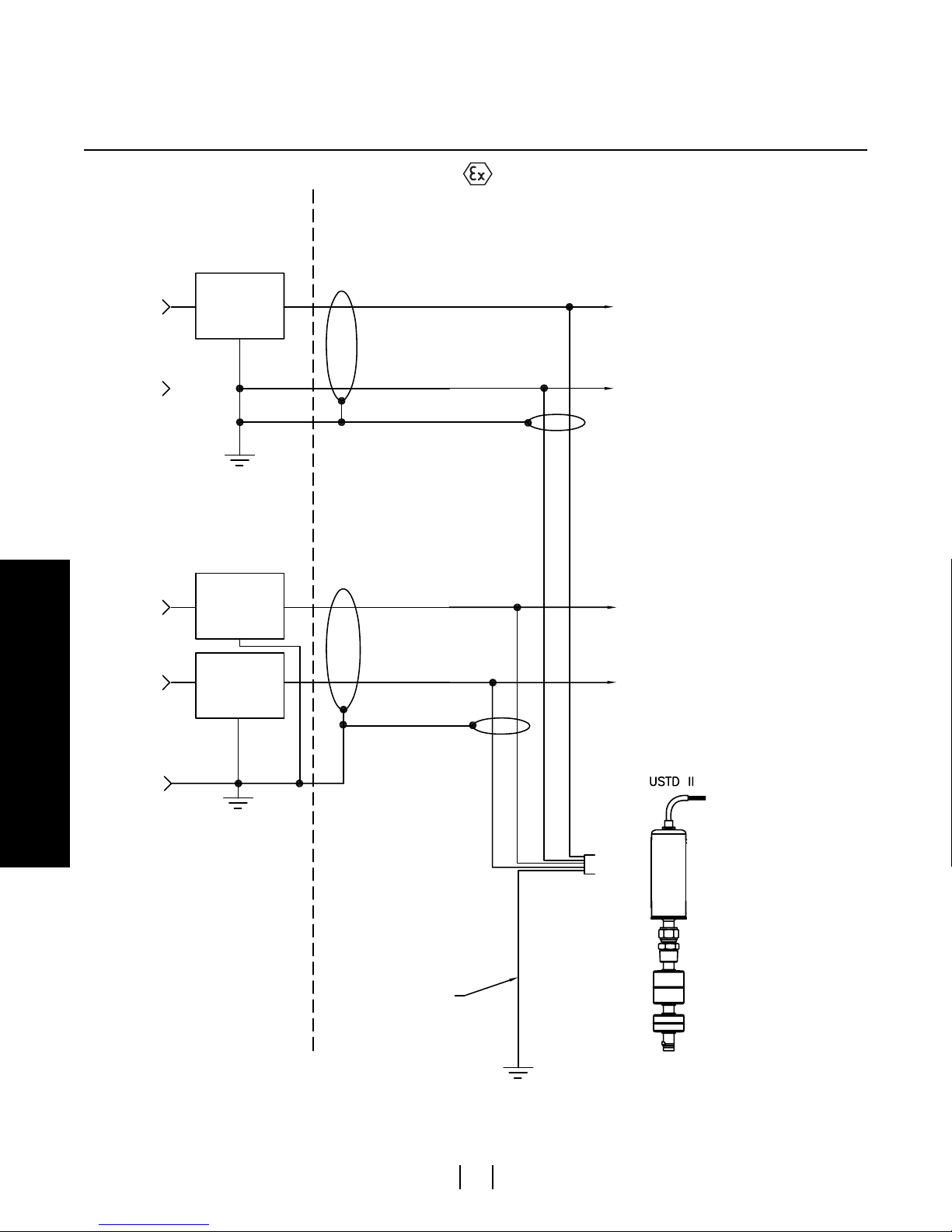
Figure 1. Safety barrier connections
Level Plus® Liquid-Level Sensors - M-Series Model USTDII Digital Transmitter
Brief Operation Manual for Safe Use, Document Number: 551412 Revision A, 04/13 (US) 4
MTS Sensors
Page 9
Model USTDII Brief Operation Manual for Safe Use
White
Gray
Brown
Black
Blue
Basic Wiring
IS Installation
INSTALLATION DRAWING NOTES (FIGURE 1)
Notes:
1. Safety barriers are ATEX Certified with entity parameters and must be used in an approved configuration where the following
conditions are met:
• Uo of the barrier combination is less than Ui of the transmitter.
• Io of the barrier combination is less than Ii of the transmitter.
• Co of the barrier combination is greater than the total Ci of the transmitters plus the cable capacitance.
• Lo of the barrier combination is greater than the total Li of the transmitters plus the cable capacitance.
Transmitter entity parameters:
• Ui = 28 Vdc
• ∑li = 200 mA
• Ci = negligibly low
• Li = negligibly low
2. Power supply cable must be 0,22 mm
must be less than 160 pF/m. Cable shield is connected to system ground at safety barrier end only.
3. Communications cable must be 0.22 mm
must be less than 160 pF/m. Cable shield is connected to system ground at safety barrier end only.
4. The wire connection between earth ground and the safety barrier ground terminal must be less than 1 ohm.
5. Maximum approved number of DDA or MODBUS gauges for intrinsically safe wiring networks is 6 to 8. Contact factory for
Modbus applications.
6. Connection to earth ground for transient protection circuitry.
7. Ground screw earthing hardware provided to connect gauge housing to earth ground.
8. The transducer frame shall be grounded to earth ground directly or through the equipment on which it is mounted and shall be at
the same potential as the safety barrier ground electrode.
9. Electronic equipment connected to associated apparatus must not use or generate more than 250 volts RMS.
10. Cable sets that are run together must have sufficient insulation to withstand 250 volts RMS between sets.
11. All wiring must meet the local regulations and/or other national/international standards.
2
or heavier (e.g. 1.32 mm2 AWG 16), shielded twisted pair cable. Cable capacitance
2
or heavier (e.g. 1.32 mm2 AWG 16), shielded twisted pair cable. Cable capacitance
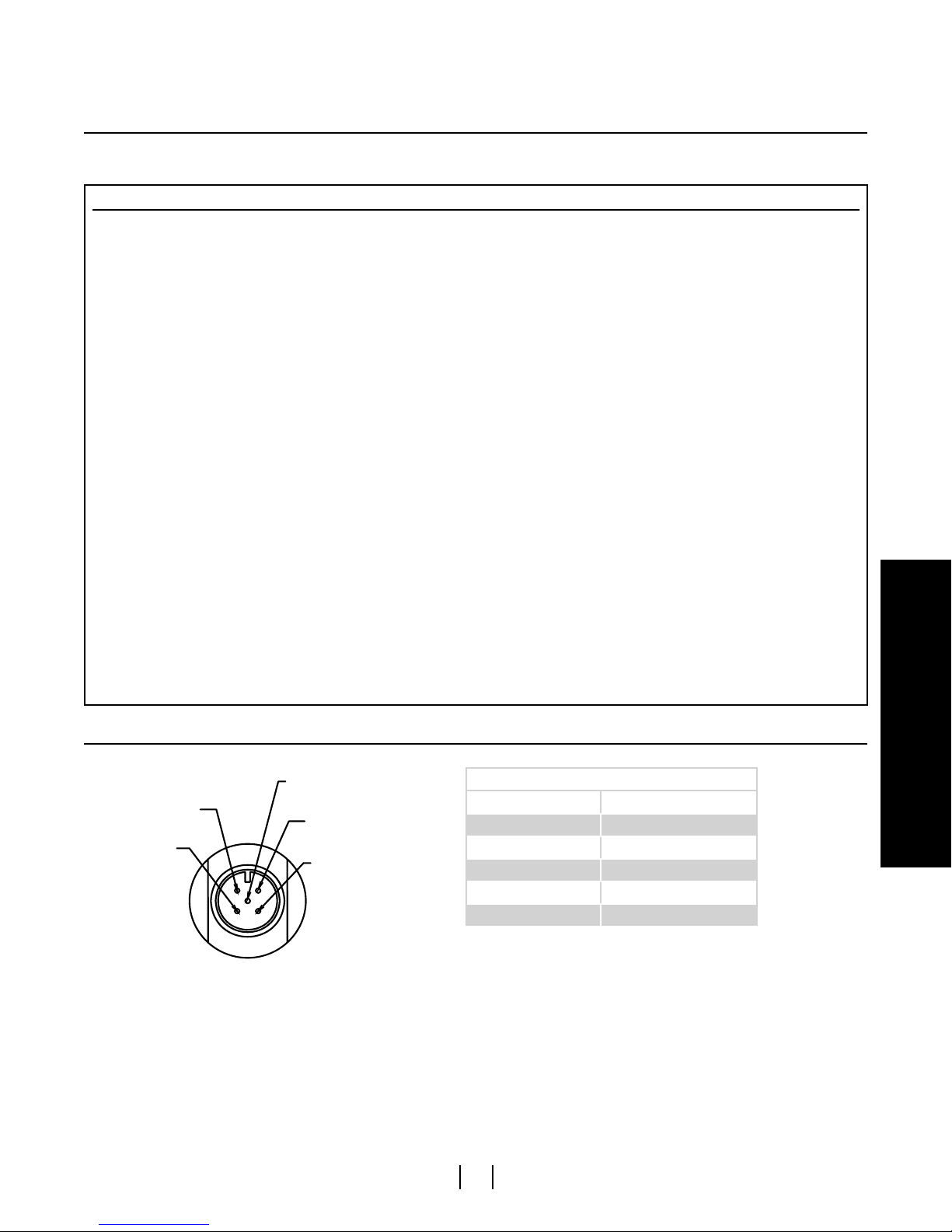
Wiring connections
Figure 2. NEMA housing with terminal strip or integral cable
MTS Sensors
Wiring diagram
Color Signal
Blue 24 Vdc Power
Black 0 Vdc Power
Gray Earth ground
Brown TXD RXD +
White TXD RXD -
Level Plus® Liquid-Level Sensors - M-Series Model USTDII Digital Transmitter
Brief Operation Manual for Safe Use, Document Number: 551412 Revision A, 04/13 (US)5
Basic Wiring
Page 10
Model USTDII Brief Operation Manual for Safe Use
Basic Wiring
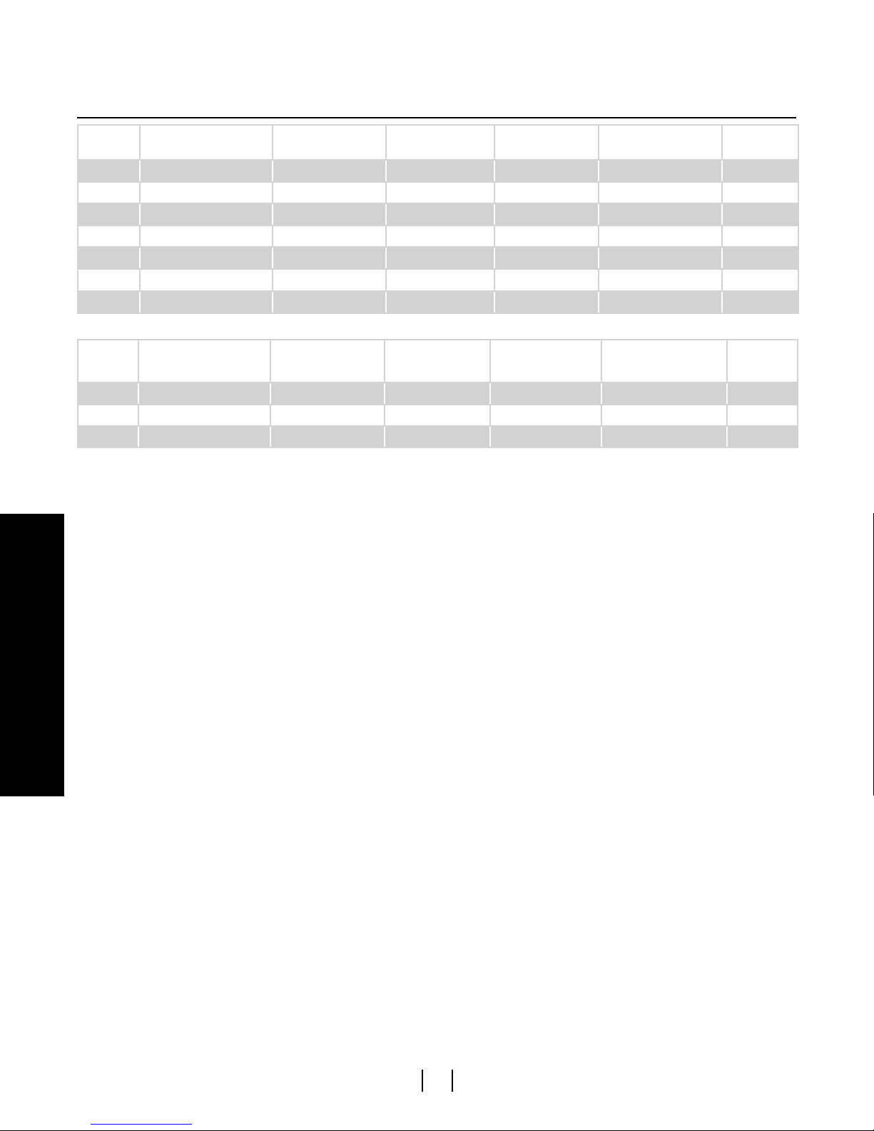
Safety barrier examples
Supplier Type
STAHL 9001/01-280-165-101 28 Vdc 165 mA 1155 mW 198Ω 1
STAHL 9001/01-280-110-101 28 Vdc 110 mA 770 mW 294Ω 1
MTL 728 28 Vdc 93 mA 651 mW 300Ω 1
MTL 728+ 28 Vdc 93 mA 651 mW 300Ω 1
MTL 7028+ 28 Vdc 93 mA 651 mW 300Ω 1
MTL 7128+ 28 Vdc 93 mA 651 mW 300Ω 1
MTL 7728+ 28 Vdc 93 mA 651 mW 300Ω 1
Table 4. Power supply (+24 Vdc)
Supplier Type
STAHL 9001/01-086-010-101 8.6 Vdc 10 mA 21.5 mW 963Ω 1
STAHL 9002/11-120-024-001 12 Vdc 12 mA 70 mW 1156Ω 2
MTL 764+ 12 Vdc 24 mA 72 mW 1075Ω 2
Table 5. Communication lines (TX/RX+ and TX/RX-)
Uo
Maximum voltageIoMaximum currentPoMaximum power Maximum resistance
Uo
Maximum voltage
Io
Maximum current
(each channel)
Po
Maximum power
(each channel)
Maximum resistance
(each channel)
Number of
channels
Number of
channels
Basic Wiring
Level Plus® Liquid-Level Sensors - M-Series Model USTDII Digital Transmitter
Brief Operation Manual for Safe Use, Document Number: 551412 Revision A, 04/13 (US)
6
MTS Sensors
Page 11
Model USTDII Brief Operation Manual for Safe Use
Projected surface area
Part number
9 mm
Accessories
Floats
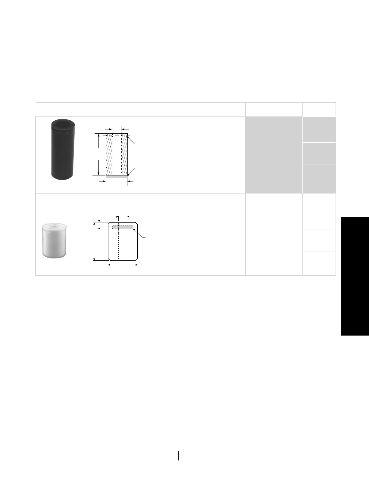
Model USTDII transmitters should be used with a float having an offset weight and made of stainless steel or Hastelloy C. This allows the float
to stay in contact with the pipe to prevent the buildup of electrostatic charge. For detailed information about floats, refer to the ‘Accessories
Catalog’, MTS part number 551103.
Non-metalic floats with a projected surface area of less than 5,000 mm² should only be used in Zone 0, Gas group IIA such as float part
numbers 201643-2, 201649-2, 201650-2, 201109, 251115 and 251116. All other non-metallic floats offered by MTS such as, 251939,
251119, 251120 and 252999, should not be used in a hazardous area application.
NITROPHYL FLOATS
Float and dimension reference
18 mm
76 mm
(3 in.)
C
L
31 mm
(1.2 in.) dia.
(.07 in.) dia.
Magnet
2356 mm²
Added weight
for interface floats
201643-2
201649-2
201650-2
TEFLON FLOATS
Float and dimension reference
(0.35 in.)
76 mm
(3 in.)
61 mm
(2.38 in.) dia.
18 mm
(0.7 in.) dia.
Centerline
of Magnet
Magnet
Projected surface area Part number
201109
4635 mm²
251115
251116
Accessories
MTS Sensors
Level Plus® Liquid-Level Sensors - M-Series Model USTDII Digital Transmitter
7
Brief Operation Manual for Safe Use, Document Number: 551412 Revision A, 04/13 (US)
Page 12

USA
EC13.004B
Model USTDII Brief Operation Manual for Safe Use
EC Declaration of Conformity
MTS Systems Corporation – Sensors Division, 3001 Sheldon Drive, Cary, NC 27513, USA
declares as manufacturer in sole responsibility that the position sensor type
erklärt als Hersteller in alleiniger Verantwortung, dass der Positionssensor Typ
déclare en qualité de fabricant sous sa seule responsabilité que les capteurs position de type
Level Plus USTDII-xxxxx-a-b a = 6; b = 7, 9;
comply with the regulations of the following European Directives:
den Vorschriften folgender Europäischen Richtlinien entsprechen:
sont conformes aux prescriptions des directives européennes suivantes :
2014/34/EU Equipment and protective systems for use in potentially explosive atmospheres
Agency
2014/30/EU Electromagnetic Compatibility
Geräte und Schutzsysteme zur Verwendung in explosionsgefährdeten Bereichen
Appareils et systèmes de protection à être utilisés en atmosphères explosibles
Elektromagnetische Verträglichkeit
Compatibilité électromagnétique
EU Declaration of Conformity
EU-Konformitätserklärung
Déclaration UE de Conformité
Applied harmonized standards:
Angewandte harmonisierte Normen:
Normes harmonisées appliquées :
EN 60079-0:2012/A11:2013, EN 60079-11:2012, EN 60079-26:2015
EN 61326-1:2013
EC type examination certificate:
EG-Baumusterprüfbescheinigung: PTB 04 ATEX 2107 X
Certificat de l’examen CE de type :
issued by / ausgestellt durch / exposé par: Physikalisch-Technische Bundesanstalt (PTB)
Notified body for quality assurance control: Factory Mutual (FM)
Benannte Stelle für Qualitätsüberwachung: Windsor, United Kingdom
Organisme notifié pour l’assurance qualité :
Ident number / Kennnummer / Numéro d’identification : 1725
Marking / Kennzeichnung / Marquage :
, EN 61326-2-3:2013
Braunschweig, GERMANY
e II 1/2G EEx ia llB T4 resp.
e II 2G EEx ia IIB T4 resp.
e II 1/2G EEx ia llA T4 resp.
e II 2G EEx ia llA T4
MTS Sensors Divison • Cary • 2017-02-27
______________________________________
Dr.-Ing. Eugen Davidoff
Approvals Manager
Ex-authorized representative
MTS Systems Corporation
Sensors Division
3001 Sheldon Drive
Cary, NC 27513
Page 1 of 1
Level Plus® Liquid-Level Sensors - M-Series Model USTDII Digital Transmitter
Brief Operation Manual for Safe Use, Document Number: 551412 Revision A, 04/13 (US) 8
MTS Sensors
Page 13

Page 14
Document Part Number: 551412 Revision A, 02/17 (US)
MTS, Temposonics and Level Plus are registered trademarks of MTS Systems Corporation. All other trademarks are the property of their respective owners.
All specifications are subject to change. Contact MTS for specifications and engineering drawings that are critical to your application. Drawings contained in this
Printed in USA. Copyright © 2017 MTS Systems Corporation. All Rights Reserved in all media.
document are for reference only. Go to http://www.mtssensors.com for the latest product information.
MTS Systems Corporation
Sensors Division
3001 Sheldon Drive
Cary, North Carolina,
27513, USA
Tel.: +1-800-633-7609
Fax: +1-919-677-2343
+1-800-498-4442
www.mtssensors.com
MTS Sensor Technologie
GmbH & Co. KG
Auf dem Schüffel 9
D - 58513 Lüdenscheid, Germany
Tel.: +49-2351-9587-0
Fax: +49-2351-56491
www.mtssensors.com
MTS Sensors Technology
Corporation
737 Aihara-machi, Machida-shi
Tokyo 194-0211, Japan
Tel.: +81-42-775-3838
Fax: +81-42-775-5516
www.mtssensors.com
 Loading...