

digiSOUNDdigiSOUNDdigiSOUND
602602
PROFESSIONAL SOUND SYSTEMS FOR SCALE MODELSPROFESSIONAL SOUND SYSTEMS FOR SCALE MODELSPROFESSIONAL SOUND SYSTEMS FOR SCALE MODELS
Introduction.
Congratulations on the purchase of your Mtroniks locomotive sound module.
Throughout the design process we have striven to make the digiSOUND sound module easy to use whilst at the same time
offering as realistic a sound as possible.
The sounds reproduced by the digiSOUND sound modules are sampled from actual locomotives, they are not synthesized
sounds. This is what allows the digiSOUND602 to produce such realistic sounds.
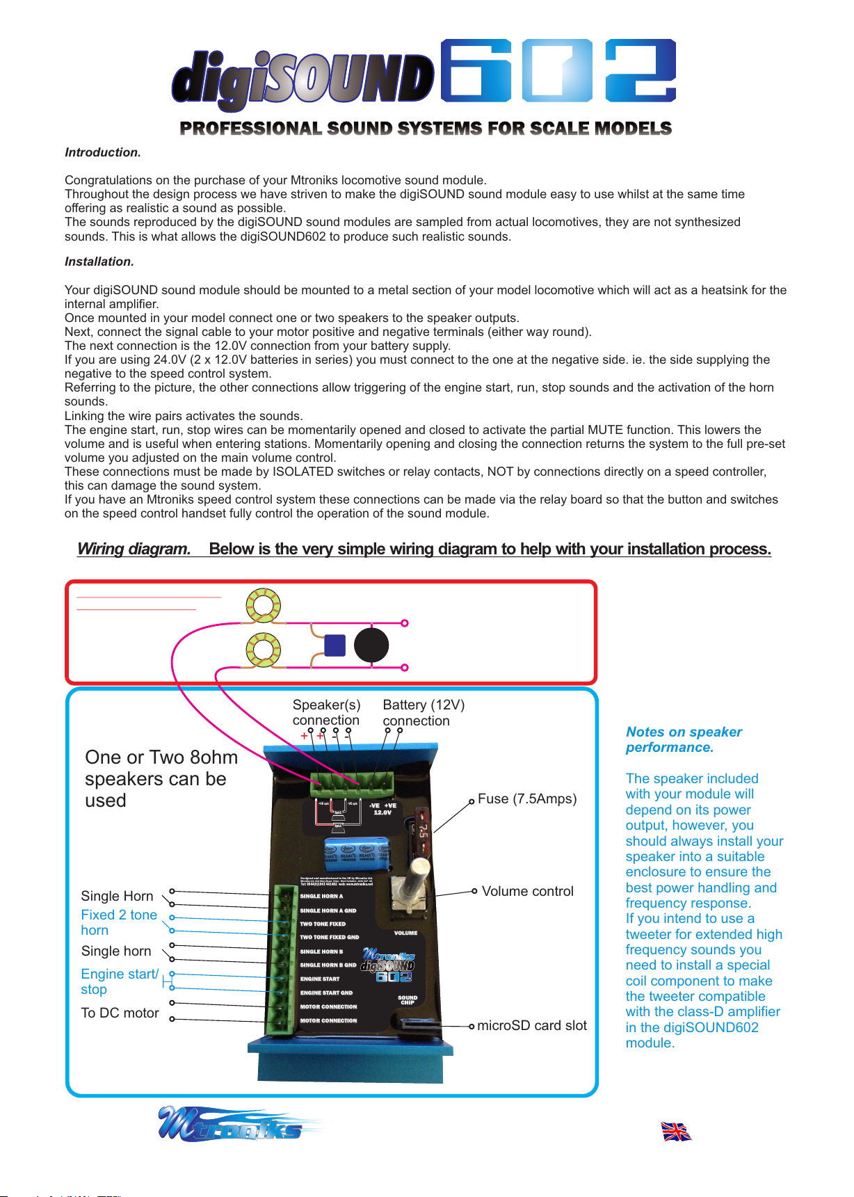
Installation.
Your digiSOUND sound module should be mounted to a metal section of your model locomotive which will act as a heatsink for the
internal amplifier.
Once mounted in your model connect one or two speakers to the speaker outputs.
Next, connect the signal cable to your motor positive and negative terminals (either way round).
The next connection is the 12.0V connection from your battery supply.
If you are using 24.0V (2 x 12.0V batteries in series) you must connect to the one at the negative side. ie. the side supplying the
negative to the speed control system.
Referring to the picture, the other connections allow triggering of the engine start, run, stop sounds and the activation of the horn
sounds.
Linking the wire pairs activates the sounds.
The engine start, run, stop wires can be momentarily opened and closed to activate the partial MUTE function. This lowers the
volume and is useful when entering stations. Momentarily opening and closing the connection returns the system to the full pre-set
volume you adjusted on the main volume control.
These connections must be made by ISOLATED switches or relay contacts, NOT by connections directly on a speed controller,
this can damage the sound system.
If you have an Mtroniks speed control system these connections can be made via the relay board so that the button and switches
on the speed control handset fully control the operation of the sound module.
Wiring diagram. Below is the very simple wiring diagram to help with your installation process.
*Optional Tweeter package.
Sold seperately £29.99
Speaker(s)
connection
- -+ +
TWEETER
Battery (12V)
connection
Standard
speaker
connection
Note: The high freq. filter
capacitor is fitted inside
the tweeter supplied.
If you intend to use a
different tweeter please
call Mtroniks for advice
Notes on speaker
performance.
One or Two 8ohm
speakers can be
used
Single Horn
Fixed 2 tone
horn
Single horn
Engine start/
stop
To DC motor
+VE spk -VE spk
Spk1
Spk2
Designed and manufactured in the UK by Mtroniks Ltd.
Mtroniks Ltd. 41A Ilkley Road - Otley - West Yorkshire - LS21 3LP - UK
Tel: 0044(0)1943 461482 web: www.mtroniks.net
SINGLE HORN A
SINGLE HORN A
SINGLE HORN A GND
SINGLE HORN A GND
TWO TONE FIXED
TWO TONE FIXED
TWO TONE FIXED GND
TWO TONE FIXED GND
SINGLE HORN B
SINGLE HORN B
SINGLE HORN B GND
SINGLE HORN B GND
ENGINE START
ENGINE START
ENGINE START GND
ENGINE START GND
MOTOR CONNECTION
MOTOR CONNECTION
MOTOR CONNECTION
MOTOR CONNECTION
digiSOUND
digiSOUNDdigiSOUND
-VE
-VE
12.0V
12.0V
602
602602
+VE
+VE
VOLUME
VOLUME
SOUND
SOUND
CHIP
CHIP
Fuse (7.5Amps)
Volume control
microSD card slot
The speaker included
with your module will
depend on its power
output, however, you
should always install your
speaker into a suitable
enclosure to ensure the
best power handling and
frequency response.
If you intend to use a
tweeter for extended high
frequency sounds you
need to install a special
coil component to make
the tweeter compatible
with the class-D amplifier
in the digiSOUND602
module.
Designed and manufactured in the UK by Mtroniks Ltd. Designed and manufactured in the UK by Mtroniks Ltd.
Mtroniks Ltd. 41A Ilkley Road - Otley - West Yorkshire - LS21 3LP - UK Tel: 0044(0)1943 461482 web: www.mtroniks.net Mtroniks Ltd. 41A Ilkley Road - Otley - West Yorkshire - LS21 3LP - UK Tel: 0044(0)1943 461482 web: www.mtroniks.net
Mtroniks Ltd. 41A Ilkley Road - Otley - West Yorkshire - LS21 3LP - UK Tel: 0044(0)1943 461482 web: www.mtroniks.net Mtroniks Ltd. 41A Ilkley Road - Otley - West Yorkshire - LS21 3LP - UK Tel: 0044(0)1943 461482 web: www.mtroniks.net
Designed and manufactured in the UK by Mtroniks Ltd. Designed and manufactured in the UK by Mtroniks Ltd.
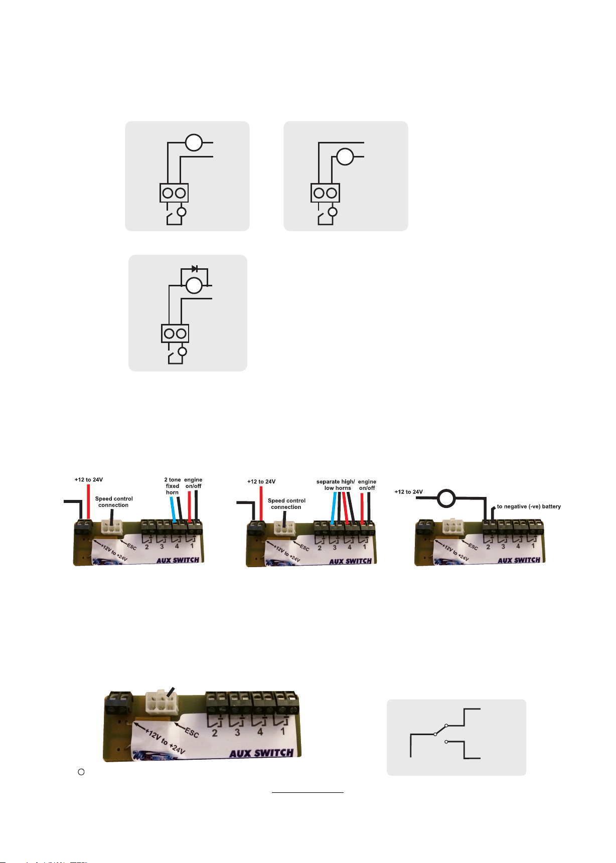
Connection of ACI/DCI Solid State Relay board
The above diagrams show the types of solid state relay board's 4 channels, control connector and positive battery
terminal.
Each channel is controlled by one of the auxiliary switches on the ACI/DCI's handset, each has a current carrying
capacity of 20A.
The relays are solid state, they have no moving parts. When connecting the contact it can either be used to switch
the positive feed or be placed in the negative, but be sure that the negative (-ve) terminal is always ‘most’ negative.
lights etc.
x
+ve
-ve
or
lights etc.
x
+ve
-ve
x x
x x
--
If switching an inductive load, a coil motor or relay etc, then always install a diode across the coil.
+ve
M
-ve
x
x
-
The cable from the ACI/DCI unit with the 6-way connector, plugs into the connector on the relay board
Ensure all cabling is capable of carrying the currents concerned safely. Check connections are sound and correct.
Double check all connections prior to powering-up. Appropriately fuse all feeds from battery positive. If an accessory
requires only 12V, then where instructed above to connect a channel's common terminal to 24v, obviously that
terminal should be connected only to 12v (the centre point of the two batteries in a 24v system).
NB, The centre point should ALWAYS be permanently hard wired. NO SWITCHES OR CIRCUIT BREAKERS. The
power on/off for the model, and its fuse should ONLY EVER be in the POSITIVE battery wire as close to the battery
as possible.
Failure to fit a diode may
result in damage to the
solid state switch. If in
doubt contact Mtroniks for
details.
* Relay AUX numbers refer to Mtroniks ACi/DCi handset switches.
No
connection
Red push button
horn style handset wiring
No
connection
2 tone toggle switch style
handset wiring
Control when not using Mtroniks ACI/DCI unit
To activate your relay board’s channel, connect one end of
chosen
your switch to battery negative and the other end of your switch to
the chosen control connector pin ( )
1,2,3 4or
Control
4
123
lights etc.
x
Typical connection of
lights
If you are wanting to use a double throw
switch, see example below, connect the
centre connection on the switch to battery
negative and the two outer connections to the
two chosen control connector pins ( )1,2,3 4or
e.g
to battery -ve
to
control
to
control
LIMITED WARRANTY
Mtroniks Ltd. guarantee this product to be free from factory defects for 24 months from purchase date, verified by receipts. This does not cover suitability for specific
Mtroniks Ltd. guarantee this product to be free from factory defects for 24 months from purchase date, verified by receipts. This does not cover suitability for specific
applications, components worn by use, tampering, incorrect connection, alteration to original connectors, switches or wires (apart from the fitting of an in-line fuse),
applications, components worn by use, tampering, incorrect connection, alteration to original connectors, switches or wires (apart from the fitting of an in-line fuse),
damage to batteries or other equipment through use, misuse or shipping damage. Our liability is limited to repairing or replacing units to original specification. Our
damage to batteries or other equipment through use, misuse or shipping damage. Our liability is limited to repairing or replacing units to original specification. Our
liability will not exceed the cost of the product. By using this ESC, the user accepts all liability. We reserve the right to modify this guarantee without notice.
liability will not exceed the cost of the product. By using this ESC, the user accepts all liability. We reserve the right to modify this guarantee without notice.
Copyright c Mtroniks Ltd. 2017
Copyright c Mtroniks Ltd. 2017
LIMITED WARRANTY
 Loading...