

Page 1

Revision D, July 7, 2017
Mtn View Aviation
An AP Enterprises, LLC Company
PO Box 31
Hubbard, OR 97032
MVA-B40C10M&O
Installation and Instructions
for Continued Airworthiness for
Door Steward™
In Accordance with STC SA01120SE
Contents
General Installation Instructions
Section A1. Installation Instructions applicable to Beech Model
Series 33, 35, 36, 55, 56, 58 and 95
Section A2. Installation Instructions applicable to Piper Model
Series PA23, PA24, PA28, PA30, PA32, PA34,
PA39, PA40 and PA44
Section B. Instructions for Continued Airworthiness
Section C. Part Listing
Section D. Sample FAA Form 337
Approved for Release David L. Paradis
Page 2

MVA-B40C10M&O
Rev. D, July 7, 2017
General Instructions, Page 1 of 1
General Installation Instructions
A. Introduction.
Insure that the intended aircraft is included in the eligibility of the STC. Installation to be
accomplished by an FAA licensed Airframe Mechanic and inspected by an FAA licensed
Airframe and Powerplant Mechanic with Inspection Authorization or by an FAA Part 145
Repair Station. Review all of the installation instructions before beginning the installation
process. Pay particular attention to “NOTES” and “CAUTIONS”. Inventory the kit prior
to beginning to insure it is complete. Upon completion of the installation, an FAA Form
337, Major Repair and Alteration form will need to be completed and submitted to the
FAA. A form has been provided in SECTION D. For questions, comments or problems
with this installation please contact Mtn View Aviation, PO Box 31, Hubbard, OR 97032,
Ph. (503) 981-4550, Fax (866) 554-3798, email [email protected]. Please
contact Mtn View Aviation for any in service problems or difficulties with this product.
B. Description of the Product.
The Door Steward™ is a product improvement installation that greatly improves the
operation of the aircraft doors. The installation consists of a gas spring attached to
brackets mounted on the door and the airframe. When the door is unlatched the gas
spring gently but firmly opens the door to the full open position. The gas spring while in
the open position protects the aircraft and occupants from unexpected openings and
closings by providing resistance to wind gusts and prop wash. In addition, the gas spring
is extremely simple and reliable. The weight of each door installation is ½ Lb. Closing
the door compresses the gas spring. The gas spring can easily be removed from its
brackets to facilitate removal of the aircraft door, replacement of a defective gas spring
or to conduct other maintenance.
C. Tools and Equipment Requirements.
1. Screwdriver, as required for interior removal.
2. Drill Motor or (90º drill preferred), #30 hi-speed drill and drill stop.
3. 1/8” Clecos and Cleco Pliers
4. Cherrymax G-27 Hand Riveter or suitable equivalent
5. Cherrymax rivet gage
6. Deburring tool(s) and hand files
7. Dremel or equivalent
8. Wrenches, 7/16” and 1/2”, open end
9. 12” scale or tape measure
D. General Installation Preperation.
1. Refer to the Aircraft Manufacturer’s Maintenance Instructions for information
regarding standard practices, precautions and notes.
2. It is the installer’s responsibility to insure that this approved installation does not
interfere or conflict with any other installed equipment or options previously
installed on the aircraft.
Page 3
MVA-B40C10M&O
Rev. D, July 7, 2017
SECTION A1, Page 1 of 8
SECTION A1
This section applicable to Beechcraft Model
Series 33, 35, 36, 55, 56, 58 and 95
Main Cabin Entry Doors and Baggage Doors
A. Installation Main Cabin Doors.
CAUTION:
Leave the existing factory door hold open arm in place during the initial
installation. Damage to the hinge brackets can occur if the door extends
open too far.
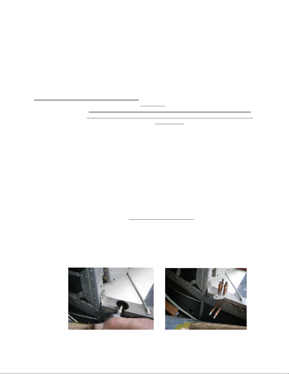
1. The airframe bracket will be located at approximately 1.0” to 3.0” aft of the most
forward point of the horizontal door sill. This will put the airframe bracket
approximately half way between the existing hold open rod pivot point and the
forward corner of the lower door sill. Select a location that avoids as many
existing rivet or screws as possible.
2. Remove or pull back the RH interior panel far enough to give access to the
airframe structure below the forward door sill. Remove or loosen any interior door
panels to expose the lower area of the door where the door bracket will be
installed. This will be just aft of the existing factory door hold open arm.
3. On some aircraft, wind lace may be installed between layers or sandwiched on
the door sill. The airframe bracket can be fitted above or between the layers.
Most often in this situation between layers gives a cleaner appearance and
allows easier reinstallation of the wind lace. The wind lace retention material will
need to be removed in the area where the bracket is to be installed. (Refer to
picture 3.)
Airframe Bracket Installation
4. Locate the airframe bracket, P/N B40C102-1, onto the lower door sill. Position as
described in step 1 above. Early aircraft may have a channel sill which extends
inboard from the structure and is utilized to secure the top of the interior
upholstery panel. This lip, if present, will need to be cut away under the bracket
just far enough to allow the lower part of the bracket to make solid contact with
the lower structure for riveting. Use a Dremel or equivalent cutoff wheel to cutoff
the lip. (Refer to Pictures 1 & 2, Beechcraft Bonanza 35)
Picture 1. Cutting out sill area Picture 2. Airframe Bracket Clecoed
(Not Required on All Installations) in place.
Page 4
MVA-B40C10M&O
Rev. D, July 7, 2017
SECTION A1, Page 2 of 8
5. In most installations the top 4 pilot holes can be utilized for attachment to the top
of the sill. On the lower part, which will be under the interior panel, locate at least
4 pilot holes best suited for attachment. Standard practices are not to locate any
holes within 2.0 times the rivet diameter from the edge or any existing holes. If
there are existing rivets in the structure removed, insure there are an equal
number of blind rivets reinstalled in that area, again insuring that you either reuse
the existing rivet hole or remain 2.0 times the rivet diameter from the existing
hole. Remove the bracket and drill the holes in the bracket that will be used for
attachment with a #30 drill bit and debur.
6. Now the airframe bracket will be your template, place it in position, drill
attachment holes with a #30 drill and secure with cleco’s. It may be helpful to
use a drill stop.
7. Remove the bracket and debur the holes drilled in the airframe.
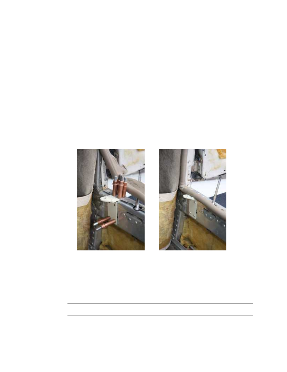
8. Cleco the airframe bracket in place. Use a cherrymax measuring tool to size the
correct length of rivet, either CR3213-4-2 or CR3213-4-3. Install the bracket with
the correct rivets. (refer to Pictures 3 & 4, Beechcraft Bonanza S35)
Picture 3. Picture 4.
Note: Bracket position Bracket riveted, wind lace
between layers. reinstalled between layers
9. Inspect the installation for security and proper installation of the rivets.
10. Remove the factory door hold open arm retention device on the bottom of the
arm before reinstalling the interior panel by removing the cotter key or nut.
CAUTION: Do not remove the arm at this time as damage to the door hinge
plates can occur if the door is opened too far. It is advisable to verify that the
hold open rod can be removed as some may have corrosion issues making them
difficult to remove.
11. Reinstall the interior panel.
Page 5
MVA-B40C10M&O
Rev. D, July 7, 2017
SECTION A1, Page 3 of 8
Door Bracket Installation
12. Temporarily install the ball stud P/N MVA9004-01 onto the door bracket P/N
201C103-2. Install the rod end threaded stud of the gas spring into the mounted
airframe bracket with self-locking nut and washer and install the tube end onto
the uninstalled door bracket P/N 201C103-2 .
13. Using the door bracket as the template and the factory hold open rod still
installed, hold the aircraft door at the full open position. If the airplane does not
have a windlace installed around the door sill you may locate the bracket at the
bottom of the door and possibly avoid any interior door panel modification. If the
airplane has a wind lace you may want to hold the door bracket up off the very
bottom of the door so that the nut on the ball stud does not damage the windlace
when opening and closing the door. You may also invert the door bracket to
locate the ball stud higher on the door. Mark the location of the door bracket.
14. Remove the door bracket from the rod end of the gas spring and review the
marked location. Any interior attachment holes blocked or very near the door
bracket can be abandoned as the gas spring and other attachment holes near
the bracket will retain the interior panel in this area. Remove the ball stud from
the bracket.
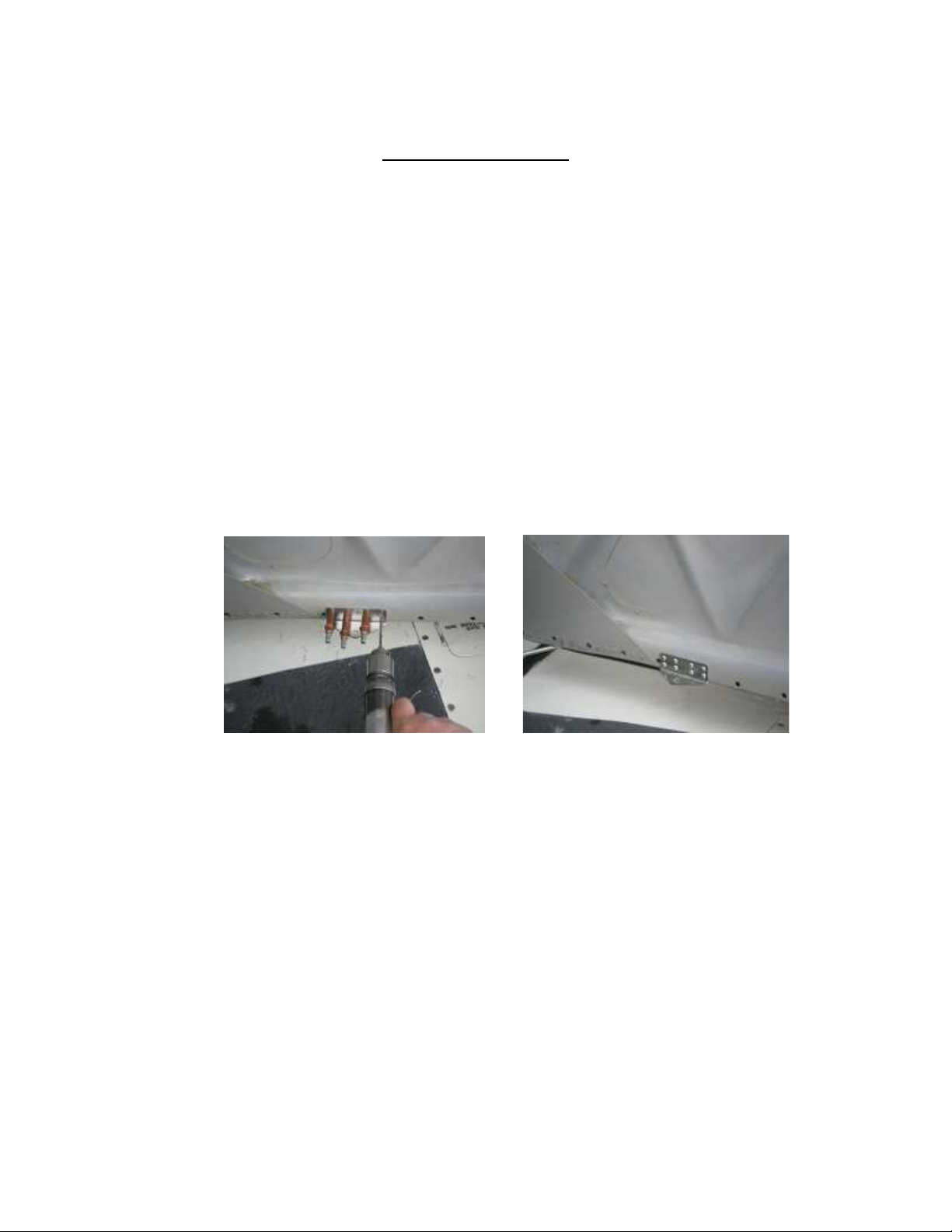
Picture 5. Drilling Door Bracket Picture 6. Door Bracket Installed
15. If satisfied with the door bracket location, position the bracket and drill all holes
with a #30 drill. Only drill through the inner door panel. It may be helpful to use a
drill stop. Debur the holes drilled in the door.
16. Cleco the door bracket in place. Use a cherrymax measuring tool to size the
correct length of rivet, either CR3213-4-2 or CR3213-4-3. Install the bracket with
the correct rivets.
17. Inspect the installed bracket for security and proper installation of the rivets.
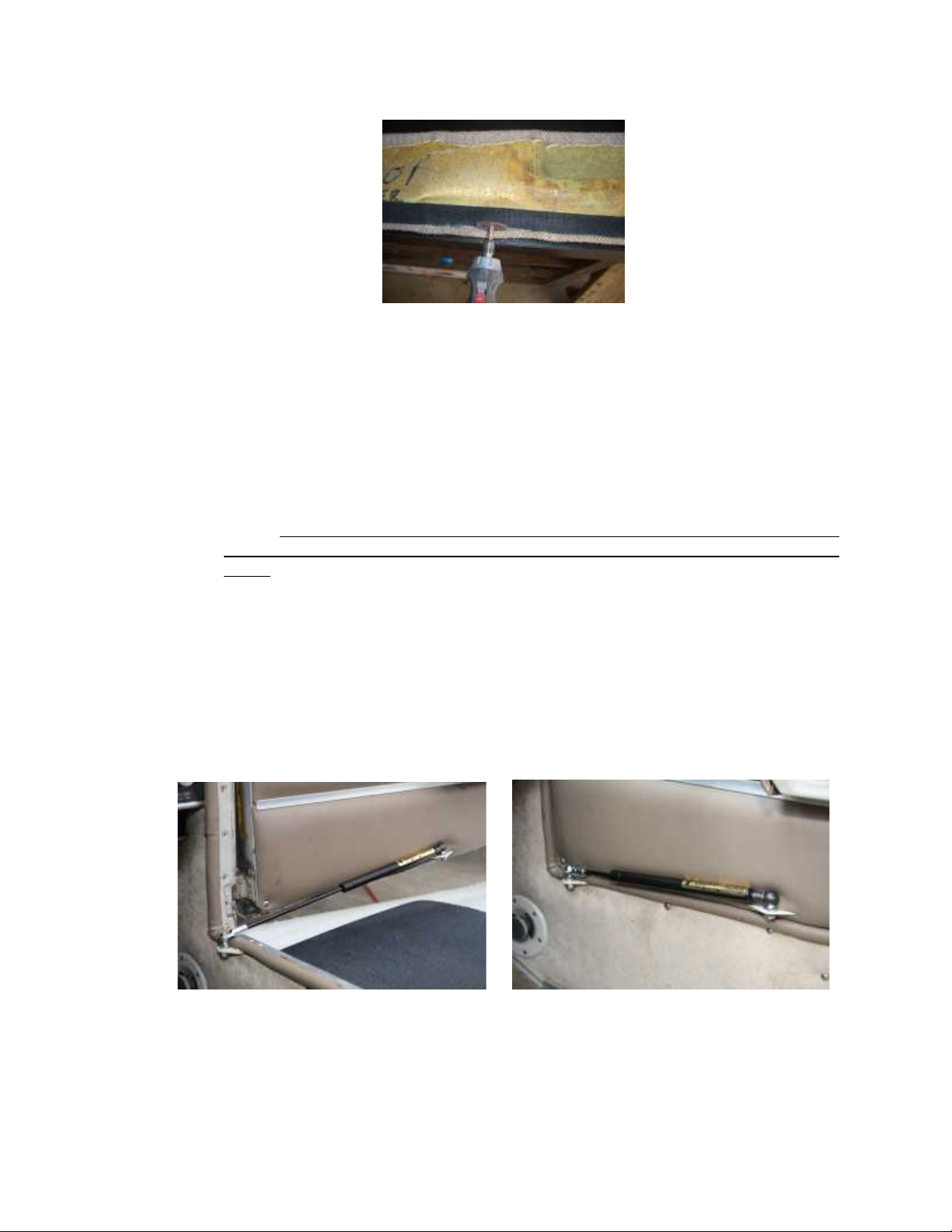
18. Hold the door interior panel in the installed position, if the door bracket extends
below the panel reinstall the panel. If the door bracket contacts the back of the
panel, note the exact contact point and use a dremel or equivalent cutoff wheel to
cut a small slot in the panel just enough to allow the bracket to protrude through.
Page 6
MVA-B40C10M&O
Rev. D, July 7, 2017
SECTION A1, Page 4 of 8
Picture 7, Slotting Interior panel on Baron.
19. Reinstall the door panel, then the ball stud on the door bracket with the supplied
washer and ¼-20 self locking nut. Torque nut to 40”lbs.
20. Remove the factory hold open rod by partially closing the door while pressing
down on the arm. There is a pin in the arm which keeps the arm in the door slot,
near the middle of the door travel this pin is aligned with the door slot at which
point the arm can be pushed down disengaging the arm from the door. The arm
can now be pulled up out of its pivot hole on the airframe provided the retention
feature was removed in step 10 above.
CAUTION: Insure the door does not open too far with hold open rod
removed and the gas spring not yet installed, as damage to the hinge plates can
occur.
21. Install the tube end of the gas spring on the door bracket. Insure the safety clip
is installed to securely lock the gas spring in place on the door bracket.
NOTE:
The gas spring is filled with nitrogen and has a small amount of oil for
dampening. The oil also acts as a lubricant for the seal so the spring
needs to be installed with the tube end up allowing the oil to keep the seal
lubricated.
Picture 8. Opened Picture 9. Closed
Note door bracket mounted up slightly
to avoid contact on the wind lace.
Page 7
MVA-B40C10M&O
Rev. D, July 7, 2017
SECTION A1, Page 5 of 8
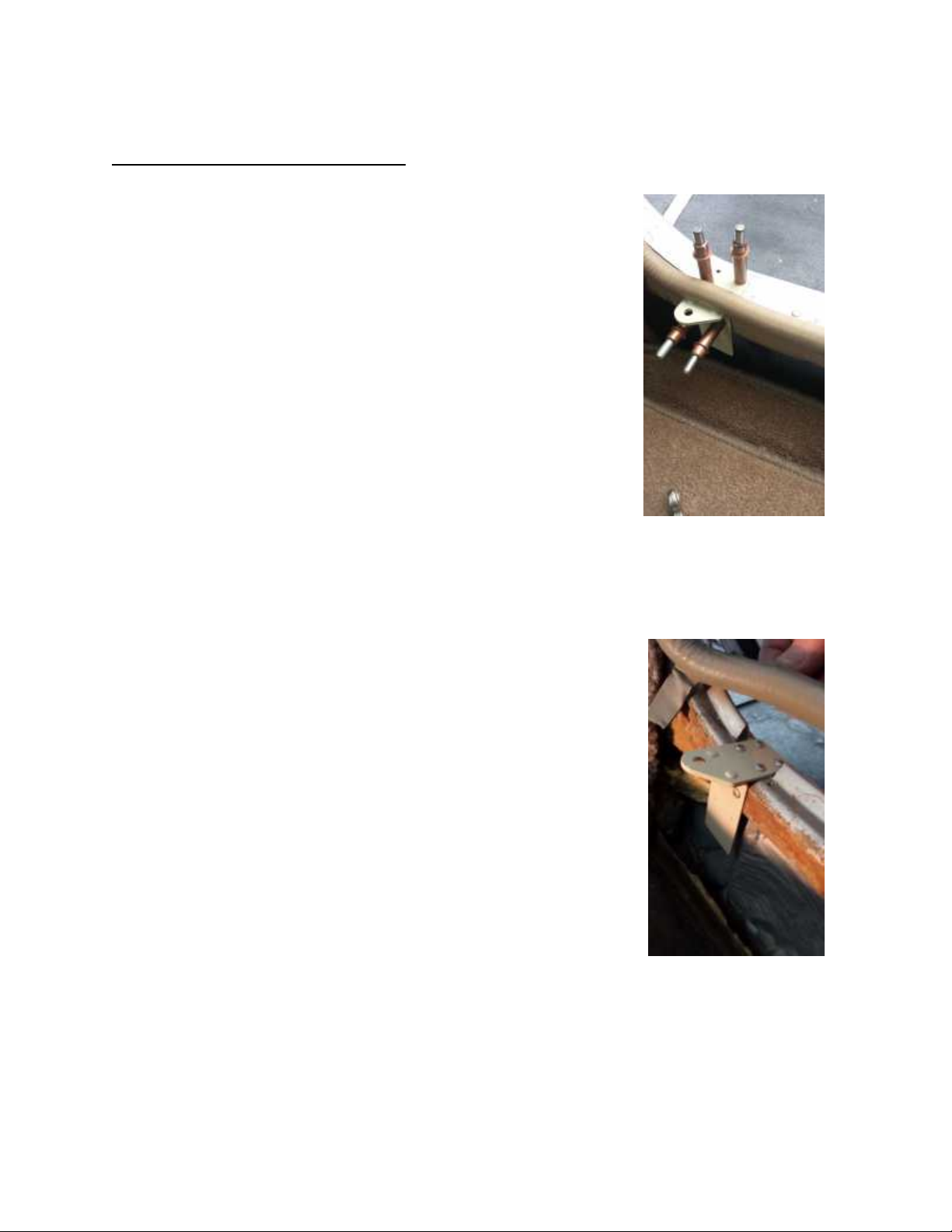
B. Installation Baggage Doors.
1. Both the standard (approx. 20 1/4” wide) and
oversize (approx. 38 1/2” wide) baggage doors are
covered by this installation section.
2. The airframe bracket, P/N B40C102-1, will be located
approximately 4” aft of the vertical door post area.
Remove any interior panels and loosen any windlace
to gain access to the door sill structure.
3. Typically the door sill associated with the oversize
baggage door has a sill cover with a raised ridge
running down the center. On this configuration the
raised portion of the sill cover the width of the
airframe bracket will need to be removed to allow the
airframe bracket to be attached to the top of the
remaining sill cover. A small cutoff tool, such as a
Dremel is good for this modification. Clean up the cut
area with a file as necessary so that the airframe
bracket will position with good contact to the sill
cover. Picture 10.
4. The airframe bracket will be attached to the door sill with 4 Cherry Max rivets
from the top down and 2 Cherry Max rivets in the inside attaching it to the side of
the door sill. It is easier to enlarge the pilot holes in the airframe bracket on a drill
press and a #30 drill.
5. Using the airframe bracket as a drill guide drill the
door sill for the six attachment rivets, adding clecos
as you drill. Remove the airframe bracket and debur
your new holes in the sill. Check for proper rivet
length and most applications will use -2 and/or -3
length Cherry Max rivets. All B40C10 Rev “B” kits will
also include 4 each CR3213 4-4 Cherry Max rivets to
accommodate attaching the airframe bracket to the
modified door sill cover of the oversize baggage door.
If you have a Rev “A” kit and need the CR3213 4-4
rivets you will need to procure locally.
6. Attach the airframe bracket to the door sill with the
correct length Cherry Max rivets. Check that the
airframe bracket is secure to the door sill with no
relative movement or apparent looseness.
7. Any door sill windlace will need to be trimmed or slit
to accommodate going around the installed airframe bracket. Picture 11.
Page 8
MVA-B40C10M&O
Rev. D, July 7, 2017
SECTION A1, Page 6 of 8
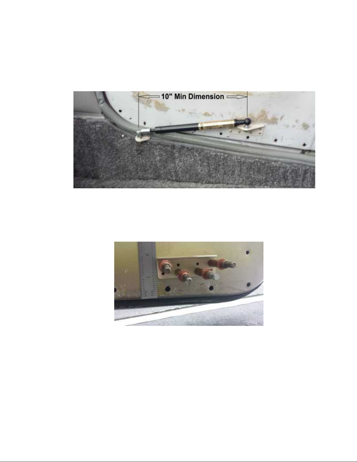
8. Install the door bracket, P/N 201C103-2 inverted on the door in a position that will be
not less than the 10” dimension as depicted in the picture with the door closed and
approximately 1” above the bottom of the door. Angle the bracket slightly to align
with the airframe bracket.
Picture 12.
Using the bracket as a drill guide, drill and cleco as you go along. When all eight
holes are drilled, remove the bracket, debur holes and then install with Cherry Max
rivets provided.
Picture 13.
9. Once the bracket is installed you will need to locate its position on the door interior
panel so you can carefully provide a slot for the bracket to protrude through. Install
the interior panel, install the threaded ball stud, P/N MVA-9004-01 with its washer
and self locking nut. Install the gas spring onto the door bracket mounted ball stud,
install the safety clip, P/N MVA-9002-01 and install the rod end with threaded stud
onto the airframe bracket with washer and self locking nut.
Page 9
MVA-B40C10M&O
Rev. D, July 7, 2017
SECTION A1, Page 7 of 8
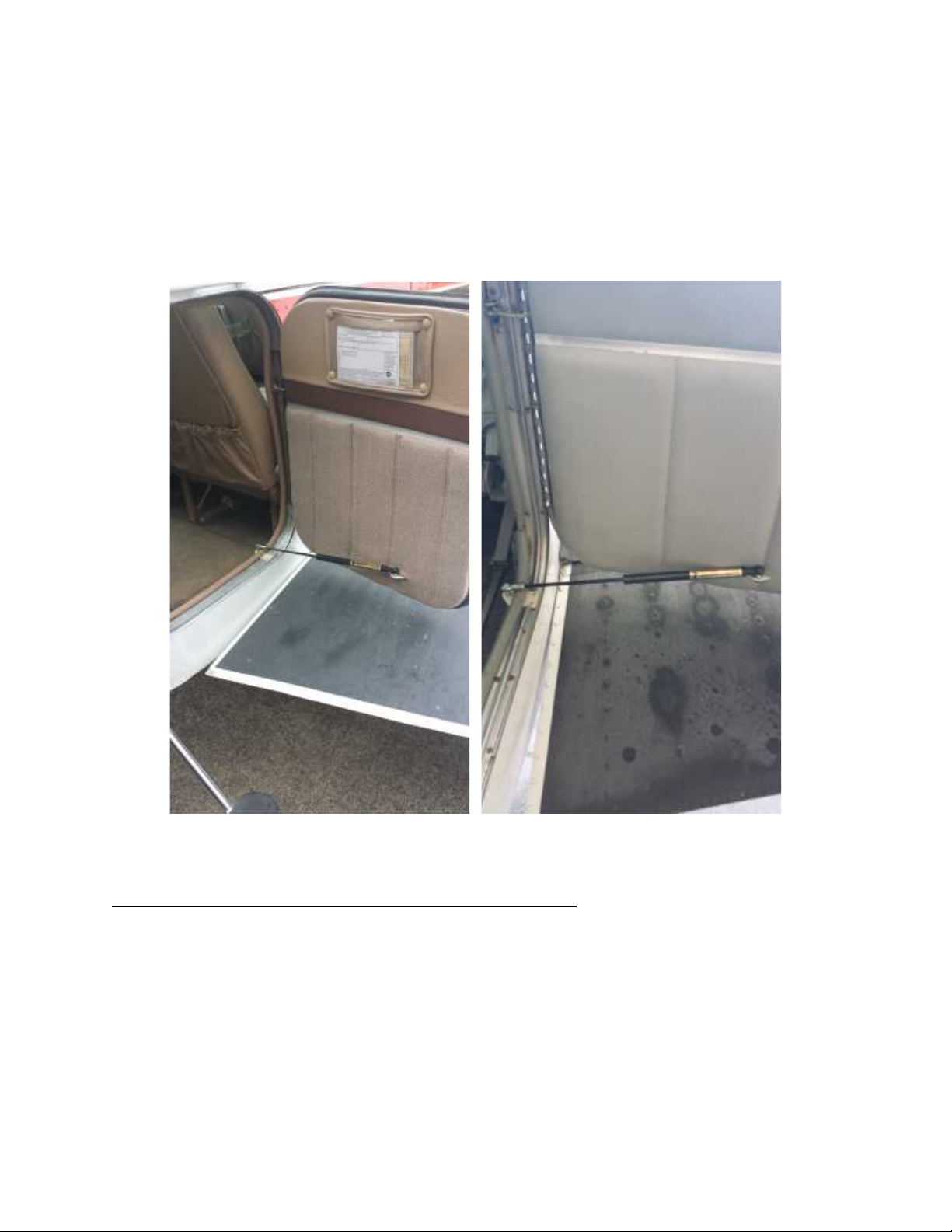
Picture 14 Small Baggage Door. Picture 15 Large Baggage Door.
C. Post Installation Inspection and Operation.
1. Operate the door(s) through several opening and closings to insure smooth and
proper operation. Close and latch the door and inspect the interior of the aircraft.
Insure the gas spring is not going to hinder or interfere with the operation of the
seats, seat belts or any other feature.
2. Open the door. Insure that in the open position the gas spring does not cause
the door any unintended contact with other structure.
3. Inspect the open position to insure the gas spring is not significantly hindering
entry and exit from the aircraft.
4. If all inspections are satisfactory, proceed to the final steps.
Page 10

MVA-B40C10M&O
Rev. D, July 7, 2017
SECTION A1, Page 8 of 8
D. Final Steps.
1. Install the supplied Door Steward™
Equipped
decal to the exterior of the
aircraft near the door latch assembly. The purpose of this decal will be to provide
an indication that when the door latch is opened; the door will want to push open
on its own.
2. Install the following SECTION B, Maintenance, Inspection & Repair Instructions
and SECTION C, Parts List, in the aircraft maintenance records.
3. Complete the FAA Form 337, Major Repair and Alteration using the included
form in SECTION D.
4. Complete the logbook entry in accordance with CFR 14 Part 43, Maintenance,
Preventive Maintenance, Rebuilding and Alteration.
5. STC Written permission statement (MVA-L-200) is provided on direct sale
transactions from Mtn View Aviation. If you did not receive this permission
statement that should be part of your permanent aircraft records, email Mtn View
Aviation at [email protected] with the aircraft make, model, serial
number, registration number, the registered owner address, date of purchase
and where purchased and one will be sent via email.
______________________________________________________________
END
Page 11
MVA-B40C10M&O
Rev. D, July 7, 2017
SECTION A2, Page 1 of 5
SECTION A2
This section applicable to Piper Model
Series PA23, PA24, PA28, PA30, PA32, PA34,
PA39, PA40 and PA44
A. Introduction.
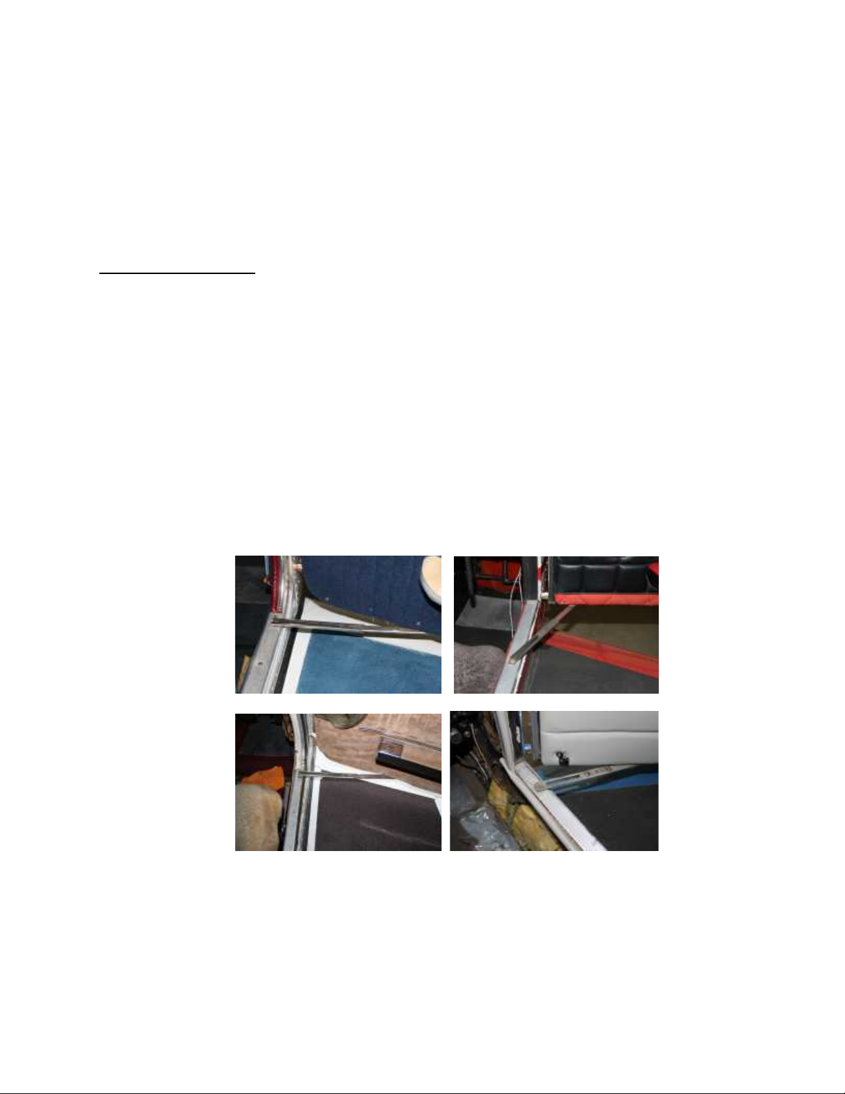
NOTE:
Most doors have a hold open slide lock attached to the airframe and door with a
10-32 screw, bushing and rubber washer. On most single engine Pipers the slide
lock attach location is approximately 4” aft of the vertical door post. The PA24
Comanche slide lock attaches further aft on the airframe and further forward on the
door. The Comanche, Apache, Aztec door sill transitions to the vertical door post
with a square corner. The other aircraft have a rounded corner. The forward side of
the airframe bracket should be located approximately 2” – 4” aft of the vertical door
post.
Twin engine Pipers have either a slide lock, like the single engine, or a hold open
lock on the engine nacelle. The slide locks will require removal, the nacelle locks
can in most cases be left installed.
1. PA28 Cherokee 2. PA24 Comanche
3. PA32 Saratoga 4. PA30 Twin Comanche
1. Remove the existing (factory) door hold open slide lock. Be careful the door does
not swing fast forward and damage the door hinges or cowl. On most single
engine aircraft there is a small bump pad attached to the cowl. For ease of
installation the door can be positioned against the cowl, tape a soft pad to the
cowl to prevent any paint scratches.
Page 12
MVA-B40C10M&O
Rev. D, July 7, 2017
SECTION A2, Page 2 of 5
2. Remove the interior door panel to expose the lower area of the door where the
door bracket will be installed. The door bracket will be located near the aft end of
the recessed area for the slide lock. Remove the co-pilot seat. Remove the sill
cover. Remove or pull back the RH interior panel far enough to give access to
the airframe structure below the forward door sill.
3. On most installations the airframe bracket will be located approximately over the
existing screw attach hole for the slide lock. On the Comanche and twins select a
location 2” – 4” aft of the vertical door post, avoiding as many existing rivets as
possible.
4. On some aircraft, wind lace may be installed on the door sill. The wind lace
retention material may need to be removed in the area where the bracket is to be
installed. If the wind lace interferes with the installation or operation of the rod
pivoting on the bracket a small amount may need to be removed or notched.
Airframe Bracket Installation
5. Locate the airframe bracket, P/N B40C102-1, onto the lower door sill. Position as
described in step 3 above. In most installations the top 4 pilot holes can be
utilized for attachment to the top of the sill. If the bracket fits over the existing
screw attach hole, locate the hole on the forward portion of the bracket between
the forward pilot holes, and make sure the bracket is in its exact location when
marking the hole. The screw will take the place of the 2 forward rivets. On the
lower part, which will be under the interior panel, locate at least 4 pilot holes best
suited for attachment. Standard practices are not to locate any holes within 2.0
times the rivet diameter from the edge or any existing holes. If there are existing
rivets in the structure removed, insure there are an equal number of blind rivets
reinstalled in that area, again insuring that you either reuse the existing rivet hole
or remain 2.0 times the rivet diameter from the existing hole. Remove the
bracket and drill the holes in the bracket that will be used for attachment with a
#30 drill bit and debur. If a screw is used in the top drill the screw hole with a
3/16”drill bit.
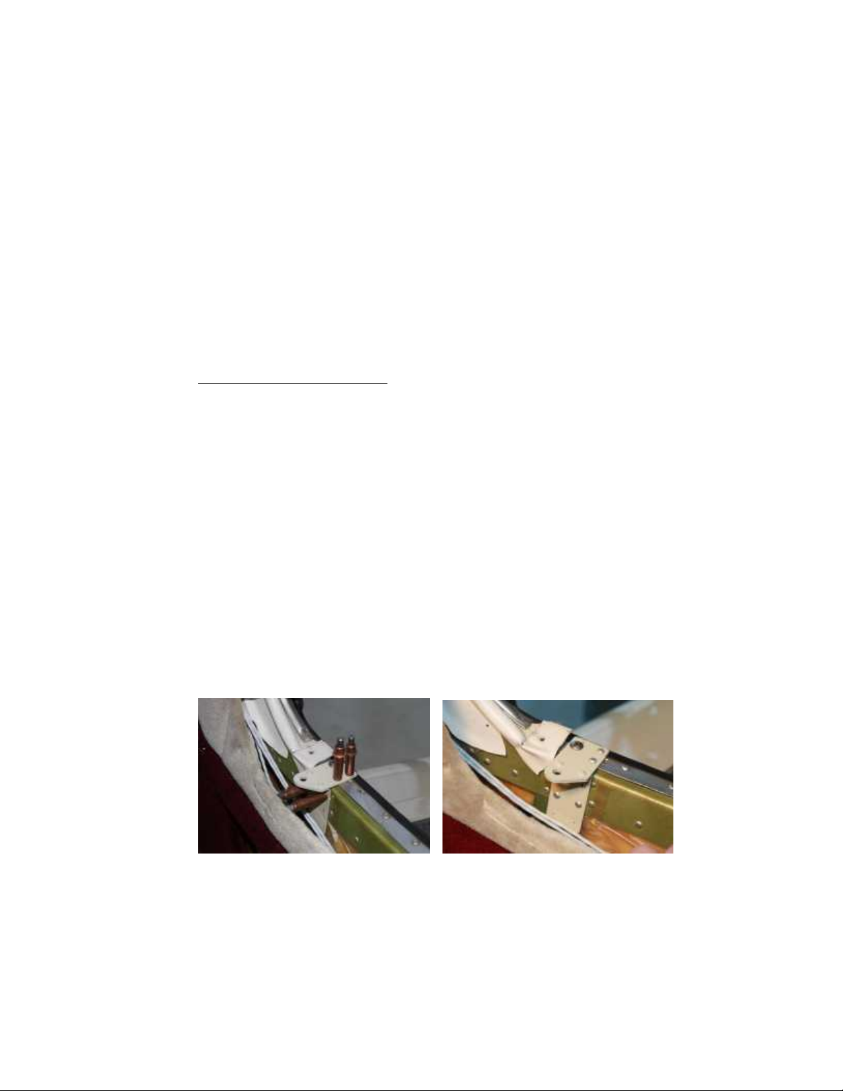
5. Airframe Bracket utilized existing 6. Airframe bracket attached
Slide lock screw attachment (Note: bottom 2 pilot holes not used)
6. Now the airframe bracket will be your template, place it in position, and if a screw
is used, install the screw before drilling the airframe holes, (AN526-1032R10
preferred, not furnished). Drill attachment holes with a #30 drill and secure with
cleco’s. It may be helpful to use a drill stop.
7. Remove the bracket and debur the holes drilled in the airframe.
Page 13
MVA-B40C10M&O
Rev. D, July 7, 2017
SECTION A2, Page 3 of 5
8. Cleco the airframe bracket in place. Use a cherrymax measuring tool to size the
correct length of rivet, either CR3213-4-2 or CR3213-4-3. Install the bracket with
the correct rivets. (refer to Pictures 5 & 6)
9. Inspect the installation for security and proper installation of the rivets.
10. Notch or slot the sill cover for the new bracket with a dremel or equivalent cutoff
wheel and reinstall, reinstall the interior panel and seat.
Door Bracket Installation
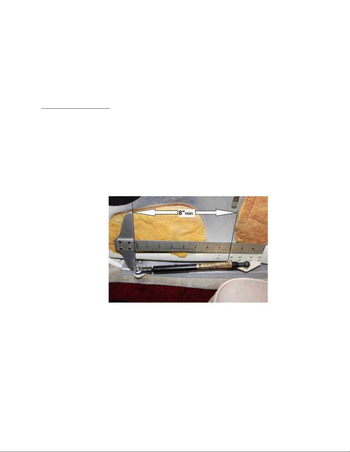
11. Single Engine - Using the door bracket, a 12 inch ruler or tape measure and
pencil, close the door and latch. Measure from the center of the installed airframe
bracket gas spring attach hole to the forward end of the door bracket. The
bracket should be placed at the bottom of the door, flush with the recessed area
for the slide lock at a distance of not less than 8”. Mark a pencil line on the door
to indicate the location. Pay particular attention to this measurement, installing
the door bracket any less than 8” from the airframe bracket will bottom the gas
spring before the door is fully closed and more than 8” starts to limit the full open
position. Any interior attachment holes blocked or very near the door bracket can
be abandoned as the gas spring and other attachment holes near the bracket will
retain the interior panel in this area.
7. NOTE: DOOR BRACKET MUST NOT BE CLOSER
THAN 8” FROM THE AIRFRAME BRACKET.
12. Twin Engine – Temporarily install the ball stud P/N MVA-9004-01 onto the door
bracket P/N 201C103-2. Install the rod end of the gas spring onto the mounted
airframe bracket and install the tube end onto the uninstalled door bracket P/N
201C103-2. Using the door bracket as the template hold the aircraft door at the
full open position, approximately ½” from the engine nacelle, mark the location of
the door bracket on the door. Insure the bracket is located at the bottom of the
door. Remove the door bracket from the rod end of the gas spring and review the
marked location. Any interior attachment holes blocked or very near the door
bracket can be abandoned as the gas spring and other attachment holes near
the bracket will retain the interior panel in this area. Remove the ball stud from
the bracket.
Page 14
MVA-B40C10M&O
Rev. D, July 7, 2017
SECTION A2, Page 4 of 5
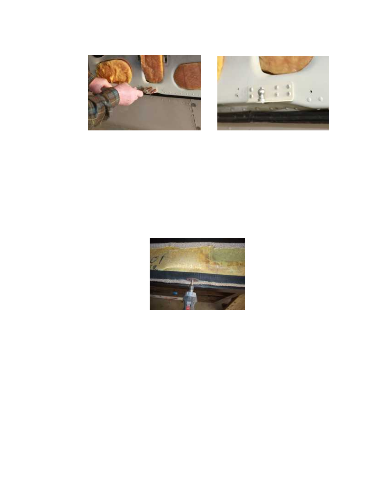
8. Installing Door Bracket 9. Door Bracket installed
13. If satisfied with the door bracket location, position the bracket and drill all holes
with a #30 drill. Only drill through the inner door panel. It may be helpful to use a
drill stop. Debur the holes drilled in the door.
14. Cleco the door bracket in place. Use a cherrymax measuring tool to size the
correct length of rivet, either CR3213-4-2 or CR3213-4-3. Install the bracket with
the correct rivets.
15. Inspect the installed bracket for security and proper installation of the rivets.
16. Hold the door interior panel in the installed position, if the door bracket extends
below the panel, reinstall the panel. If the door bracket contacts the back of the
panel, note the exact contact point and use a dremel or equivalent cutoff wheel to
cut a small slot in the panel just enough to allow the bracket to protrude through.
10. Slotting Interior panel.
17. Reinstall the door panel, then the ball stud on the door bracket with the supplied
washer and ¼-20 self locking nut. Torque the nut to 40”lbs.
18. Install the tube end of the gas spring on the door bracket. Insure the safety clip
is installed to securely lock the gas spring in place on the door bracket. Attach
the rod end to the airframe bracket with the supplied washer and ¼-28 selflocking nut.
NOTE:
The gas spring is filled with nitrogen and has a small amount of oil for
dampening. The oil also acts as a lubricant for the seal so the spring
needs to be installed with the tube end up allowing the oil to keep the seal
lubricated.
Page 15
MVA-B40C10M&O
Rev. D, July 7, 2017
SECTION A2, Page 5 of 5
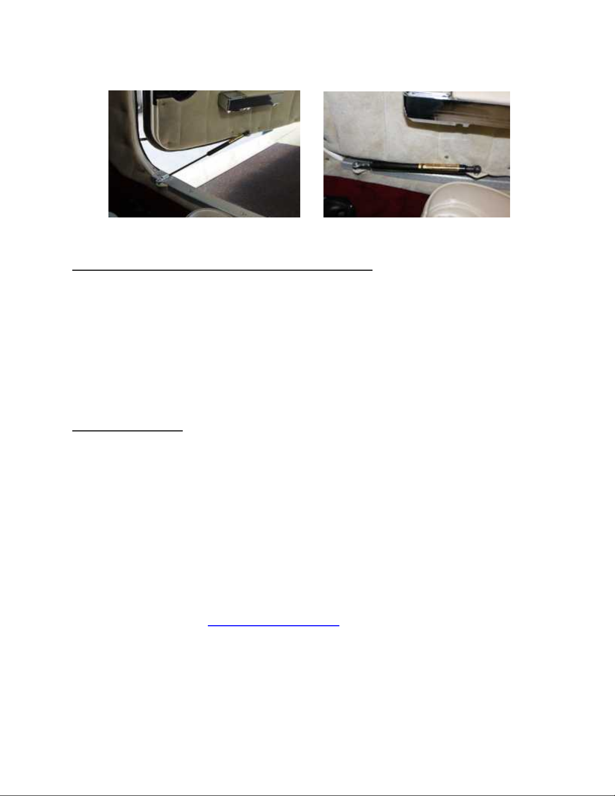
Picture 11. Opened Picture 12. Closed
Note door bracket mounted up slightly
B. Post Installation Inspection and Operation.
1. Operate the door through several opening and closings to insure smooth and
proper operation. Close and latch the door and inspect the interior of the aircraft.
Insure the gas spring is not going to hinder or interfere with the operation of the
seats, seat belts or any other feature.
2. Open the door. Insure that in the open position the gas spring does not cause
the door any unintended contact with other structure.
3. Inspect the open position to insure the gas spring is not significantly hindering
entry and exit from the aircraft.
4. If all inspections are satisfactory, proceed to the final steps.
C. Final Steps.
1. Install the supplied Door Steward™
Equipped
decal to the exterior of the
aircraft near the door latch assembly. The purpose of this decal will be to provide
an indication that when the door latch is opened; the door will want to push open
on its own.
2. Install the following SECTION B, Maintenance, Inspection & Repair Instructions
and SECTION C, Parts List, in the aircraft maintenance records.
3. Complete the FAA Form 337, Major Repair and Alteration using the included
form in SECTION D.
4. Complete the logbook entry in accordance with CFR 14 Part 43, Maintenance,
Preventive Maintenance, Rebuilding and Alteration.
5. STC Written permission statement (MVA-L-200) is provided on direct sale
transactions from Mtn View Aviation. If you did not receive this permission
statement that should be part of your permanent aircraft records, email Mtn View
Aviation at [email protected] with the aircraft make, model, serial
number, registration number, the registered owner address, date of purchase
and where purchased and one will be sent via email.
_____________________________________________________________
END
Page 16

MVA-B40C10M&O
Rev. D, July 7, 2017
SECTION B, Page 1 of 3
SECTION B
Instructions for Continued Airworthiness
For questions, comments or problems with this installation please
contact Mtn View Aviation, PO Box 31, Hubbard, OR 97032, Ph. (503)
981-4550, Fax (866) 554-3798, email [email protected].
Please contact Mtn View Aviation for any in service problems or
difficulties with this product.
ATA Chapter 05 Time Limits/Maintenance Checks
05-00 General
The Door Steward™ installation should be inspected
during scheduled airframe periodic inspections that cover the
door and door frame areas.
05-10 FAA Approved Airworthiness Limitations Section
The Airworthiness Limitations Section is FAA approved and
specifies maintenance required under 14 CFR §§ 43.16 and
91.403 of the Federal Aviation Regulations unless an
alternative program has been FAA approved.
There are no new (or additional) airworthiness limitations
associated with this equipment and/or installation.
05-20 Scheduled Maintenance
Inspection of the installation will consist of the following:
1. Security of attachment of both airframe and
door brackets to the associated structure.
2. Security of the gas spring attachment to their
associated brackets.
3. Security of the rod end to the airframe bracket
and ball stud to the door bracket.
4. Smooth operation of the gas spring. Inspect
for evidence of end seal leakage or loss of gas
spring pressure.
Page 17

MVA-B40C10M&O
Rev. D, July 7, 2017
SECTION B, Page 2 of 3
ATA Chapter 52 Doors
52-00 General
The Door Steward™ is a product improvement installation that greatly
improves the operation of the aircraft doors. The installation consists of a
gas spring attached to brackets mounted on the door and the airframe.
When the door is unlatched the gas spring gently but firmly opens the door
to the full open position. The gas spring while in the open position
protects the aircraft and occupants from unexpected openings and
closings by providing resistance to wind gusts and prop wash. In addition,
the gas spring is extremely simple and reliable. The weight of each door
installation is ½ Lb. The original door hold open arm is replaced by the
Door Steward™. Closing the door compresses the gas spring. The
gas spring can easily be removed from its brackets to facilitate removal of
the aircraft door, replacement of a defective gas spring or to conduct other
maintenance.
1. Removal of the gas spring from attachment ball stud(s).
On the all steel end fittings a safety clip may be installed as a
secondary retention device. The safety clip must be removed
before attempting to remove the gas spring. Grip the gas spring at
the end fitting and pull it directly up off of the ball stud. Repeat for
the opposite end if equipped with ball stud. To remove gas spring
from airframe bracket with integral stud, remove self locking nut
and washer.
2. Installation of the gas spring onto the attachment ball studs.
The all steel end fitting can be pushed onto the ball stud providing
the safety clip is not installed. Push the end fittings onto the ball
studs. The all steel end fittings come fitted with an internal circlip to
capture the ball stud. Install the optional safety clip on the all steel
end fittings, if so desired. The optional safety clip for the all steel
end fittings provides a secondary positive retention to ensure the
gas springs cannot come up off the ball stud. For gas spring with
integral stud as part of the end fitting, insert into bracket and attach
with AN365-428 self locking nut and washer.
3. Replacement of a loose or worn ball stud in either the
airframe or door bracket.
Remove the ¼-20 self locking nut and remove the ball stud.
Inspect the bracket for security of attachment to the associated
structure. Install a new P/N MVA9004, ¼-20 threaded ball stud.
Install washer and MVA9005-4 ¼-20 self-locking nut. Torque the
Page 18

MVA-B40C10M&O
Rev. D, July 7, 2017
SECTION B, Page 3 of 3
nut to 40 in. lbs. Inspect the installation for proper seating of the
ball stud in the hole and for full engagement of the nut on the stud.
4. Defective gas spring.
A gas spring that has lost its dampening effect can sometimes be
restored by removing the gas spring from the aircraft and store it
vertically with the small diameter rod down for 30 minutes at room
temperature. By hand and a sturdy work bench slowly compress
the gas spring until nearly compressed and release it so it can
extend back to full extension. Exercise in this manner a couple
times and then reinstall it on the aircraft. The installed rod end is
always to be lower than the tube end to allow the dampening oil to
be near the seal. A gas spring which has lost pressure is not
repairable. Replace defective gas spring with a new one with the
same part number as removed. Gas spring end fittings which are
damaged or worn can be replaced with new. Refer to the Parts List
in SECTION C for the correct part number.
Page 19
MVA-B40C10M&O
Rev. D, July 7, 2017
SECTION C, Page 1 of 1
SECTION C
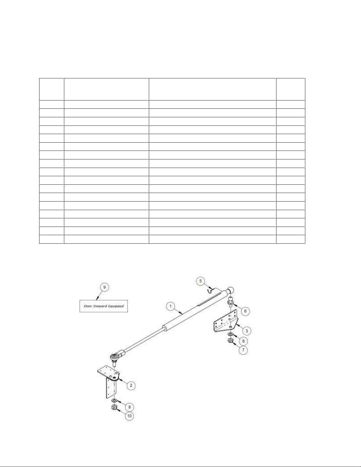
Parts List for B40C10 Installation
Item
No.
Part Number
Description
Qty
Reqd
B40C10
Installation Assembly
Ref.
1
. 201C101-21
Gas Spring Assembly
1
. . 201C101-002
Gas Spring, Chrome or Nitrided Rod
1
. . MVA-9001
End Fitting, All Steel
1
. . MVA-9008-21
Rod End Fitting, with Stud
1
. . MVA-200
Identification Label
1
2
. B40C102-1
Bracket Assembly, Airframe
1
3
. 201C103-2
Bracket, Door
1
4
. CR3213 4-2
Rivets, Blind
8
. CR3213 4-3
Rivets, Blind
8
. CR3213 4-4
Rivets, Blind
4
5
. MVA-9002-01
Safety Clip
1
6
. MVA-9004-01
Ball Stud, 10mm, ¼-20 Threads
1
7
. MVA-9005-4
Locknut, Thin, ¼-20
1
8
. AN960-416L
Washer, Thin
2
9
. MVA201
Decal, Door Steward Equipped
1
10
. AN365-428
Nut, Self-Locking ¼-28
1
Page 20

MVA-B40C10M&O
Rev. D, July 7, 2017
SECTION D, Cover Page
SECTION D
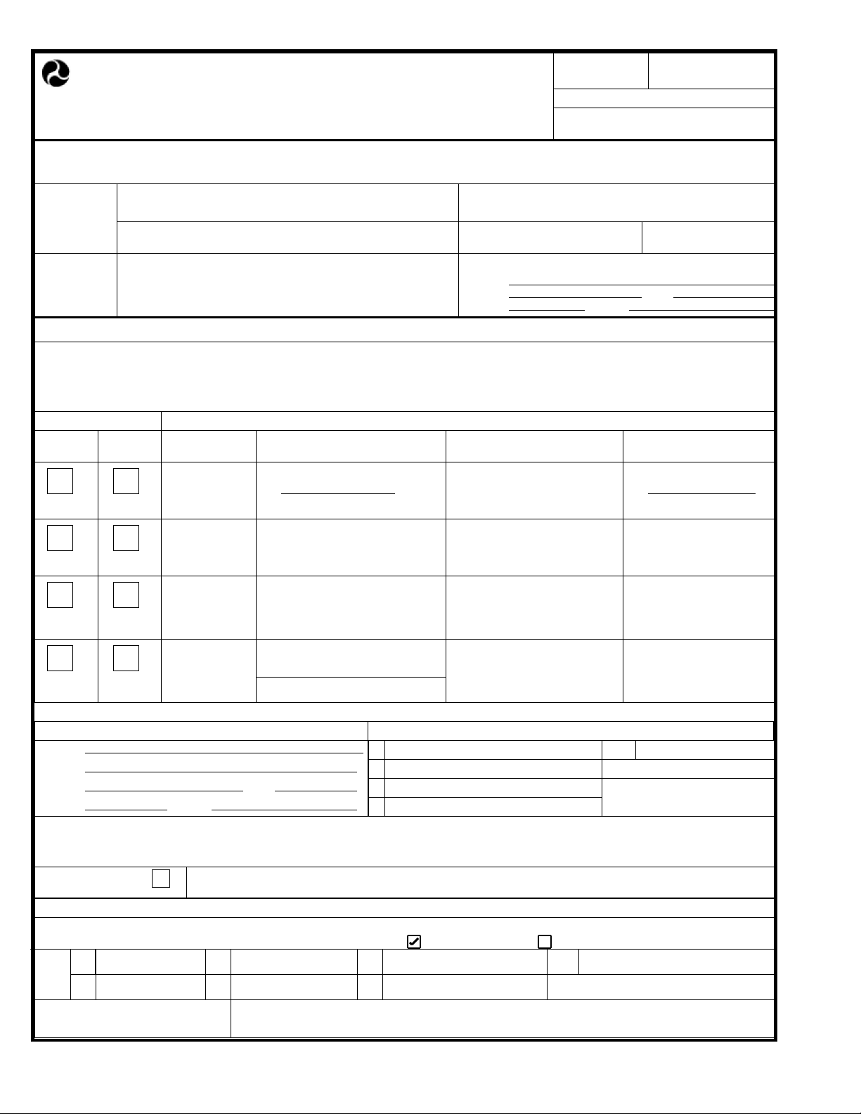
SAMPLE FAA FORM 337
Page 21
Pursuant to the authority given persons specified below, the unit identified in item 5 was inspected in the manner prescribed by
the Administrator of the Federal Aviation Administration and is
Form Approved
OMB No.2120-0020
2/28/2011
INSTRUCTIONS: Print or type all entries. See Title CFR §43.9, Part 43 Appendix B, and AC 43.9-1 (or subsequent revision thereof) for
instructions and disposition of this form. This report is required by law (49 U.S.C. §44701). Failure to report can result in a civil penalty for
each such violation (49 U.S.C. §46301(a)).
U.S. Department
of Transportation
Federal Aviation
Administration
Electronic Tracking Number
1. Aircraft
2. Owner
4. Type
MAJOR REPAIR AND ALTERATION
(Airframe, Powerplant, Propeller, or Appliance)
Nationality and Registration Mark
Make
Name (As shown on registration certificate)
Unit ModelRepair Alteration
X
AIRFRAME
3. For FAA Use Only
5. Unit Identification
Make
For FAA Use Only
Serial No.
Model
Address (As shown on registration certificate)
Address
City
Zip
Country
(As described in item 1 above)
Series
State
Serial No.
POWERPLANT
PROPELLER
APPLIANCE
Type
Manufacturer
6. Conformity Statement
A. Agency's Name and Address B. Kind of Agency
Name
Address
City
Zip
I certify that the repair and/or alteration made to the unit(s) identified in item 5 above and described on the reverse or attachments
D.
Country
State
X
U.S. Certificated Mechanic
Foreign Certificated Mechanic
Certificated Repair Station
Certificated Maintenance Organization
Manufacturer
C. Certificate No.
hereto have been made in accordance with the requirements of Part 43 of the U.S. Federal Aviation Regulations and that the
information furnished herein is true and correct to the best of my knowledge.
Extended range fuel per
14 CFR Part 43 App. B
Signature/Date of Authorized Individual
7. Approval for Return To Service
FAA Flt. Standards
BY
Certificate or Designation No.
Inspector
Manufacturer
Signature/Date of Authorized Individual
APPROVED REJECTED
Maintenance Organization
Inspection AuthorizationRepair StationFAA Designee
Person Appoved by Canadian
Department of Transport
Other
(Specify)
FAA Form 337
(10-06)
Page 22
Aircraft Total Time
the aircraft equipment list.
INSTRUCTIONS FOR CONTINUED AIRWORTHINESS
General
airframe periodic inspections that cover the door and door frame areas.
Scheduled Maintenance
Inspection of the installation will consist of the following:
associated structure.
Security of the gas spring attachment to their associated brackets.
door bracket.
seal leakage or loss of gas spring pressure.
NOTICE
Weight and balance or operating limitation changes shall be entered in the appropriate aircraft record. An alteration must be
compatible with all previous alterations to assure continued conformity with the applicable airworthiness requirements.
8. Description of Work Accomplished
(If more space is required, attach additional sheets. Identify with aircraft nationality and registration mark and date work completed.)
Nationality and Registration Mark Date
Installed the Door Steward door assist gas spring modification in accordance with STC# SA01120SE,
instructions MVA-B40C10M&O, on cabin and/or baggage door(s). Weight change negligble. Item added to
The are NO MANDATORY replacement items, structural inspection intervals or related structural inspection
procedures.
ATA Chapter 05 Time Limits/Maintenance Checks
05-00
The Door Steward ™ installation should be inspected during scheduled
05-20
1. Security of attachment of both airframe and door brackets to the
2.
3. Security of the rod end to the airframe bracket and ball stud to the
4. Smooth operation of the gas spring. Inspect for evidence of end
Additional Sheets Are Attached
FAA Form 337
(10-06)
 Loading...