


MTO-WA718N-A1 AP
Quick Installation Guide
VER : 1.0

1. Module Interface Description:
LED
LED State
Description
POWER
Light
Power status normal
SYS
Light
Start when the system power-on light
LAN
Light
Wired network connectivity
WLAN
Light
Wireless network boot
WPS
Light
One-click encryption started
① Antenna
② Power (Power Input DC5V to 12V)
③ V3.3V、RX、 GND、TX(The order from top to bottom)
④ LAN
⑤ Reset
⑥ Indicator(WPS、Wi-Fi、SYS、LAN、PWR)(The order from top to bottom)
After the connection is complete, Check that the LED is correctly:
If the LED is not lit or not properly, check that the connection is correct.

2. AP management interface
a. Set your computer's IP 192.168.0.X network segment; (X is 1-253 integer
between and not 60)
b. With a network cable to connect the computer's Ethernet port and network
interface module;
c. Then the computer's command prompt window, enter ping command; has the
following screen is connected properly;
d. In the computer's browser address bar enter 192.168.0.60; enters the AP
management interface;
Note: It is a user-specified functions of the software; The AP default mode is
Bridge, Wireless mode is Client; User name and password is admin;
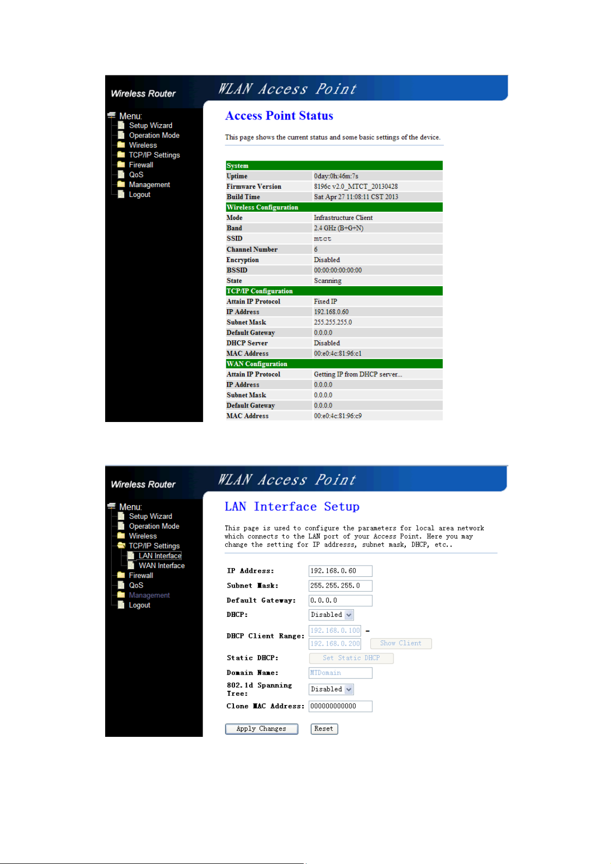
e. In this position, the IP address of the LAN can be modified;
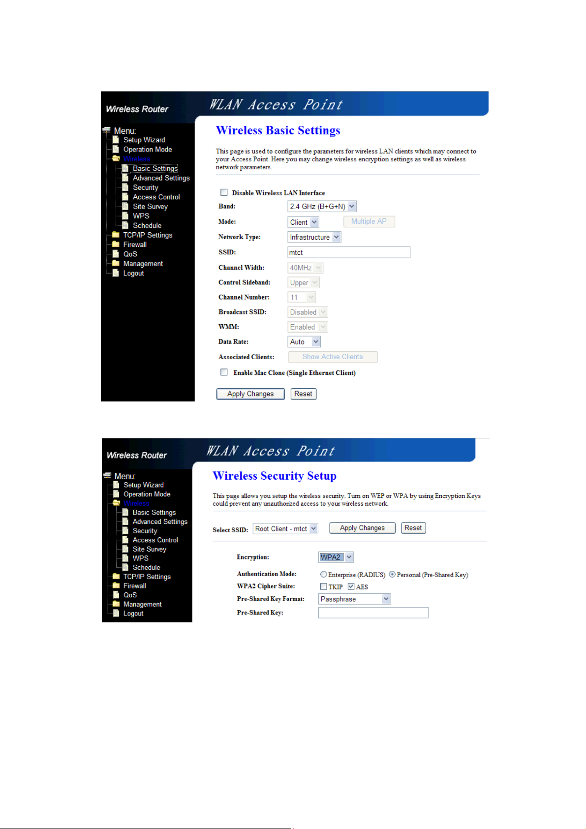
f. In this position you can modify parameters related to wireless;
g. In this position, you can set the wireless encryption;

FCC Statement
This equipment has been tested and found to comply with the limits for a Class B digital device,
pursuant to part 15 of the FCC rules. These limits are designed to provide reasonable protection against
harmful interference in a residential installation. This equipment generates, uses and can radiate radio
frequency energy and, if not installed and used in accordance with the instructions, may cause harmful
interference to radio communications. However, there is no guarantee that interferen ce will not occur
in a particular installation. If this equipment does cause harmful interference to radio or television
reception, which can be determined by turning the equipment off and on, the user is encouraged to try
to correct the interference by one or more of the following measures:
-Reorient or relocate the receiving antenna.
-Increase the separation between the equipment and receiver.
-Connect the equipment into an outlet on a circuit different from that to which the receiver is
connected.
-Consult the dealer or an experienced radio/TV technician for help.
To assure continued compliance, any changes or modifications not expressly approved by the party
responsible for compliance could void the user’s authority to operate this equipment. (Example- use
only shielded interface cables when connecting to computer or peripheral devices)
FCC Radiation Exposure Statement
This equipment complies with FCC RF radiation exposure limits set forth for an uncontrolled
environment. This transmitter must not be co-located or operating in conjunction with any other
antenna or transmitter.
This equipment complies with Part 15 of the FCC Rules. Operation is subject to the following two
conditions:
(1) This device may not cause harmful interference, and
(2) This device must accept any interference received, including interference that may cause
undesired operation.
This equipment should be installed and operated with minimum distance 20cm between the radiator
and your body.
 Loading...