

Page 1
CONNECTING LEADS
Connect the suppressor as shown in the installation diagram. Refer
to page 5 for recommended cable dressing. Connect the terminals
within the suppressor to the load side of 60A breakers within the
panel.
RECOMMENDED WIRE GAUGE
Minimum of 8 AWG
Maximum of 4 AWG ( for ease of dressing)
LENGTH OF CONNECTING LEADS
The longer the connecting leads between the the ZoneMaster and
power panel, the higher the residual transient voltage.
RECOMMENDED MAXIMUM: 19” (500mm)
IDEALLY: 10” (250mm)
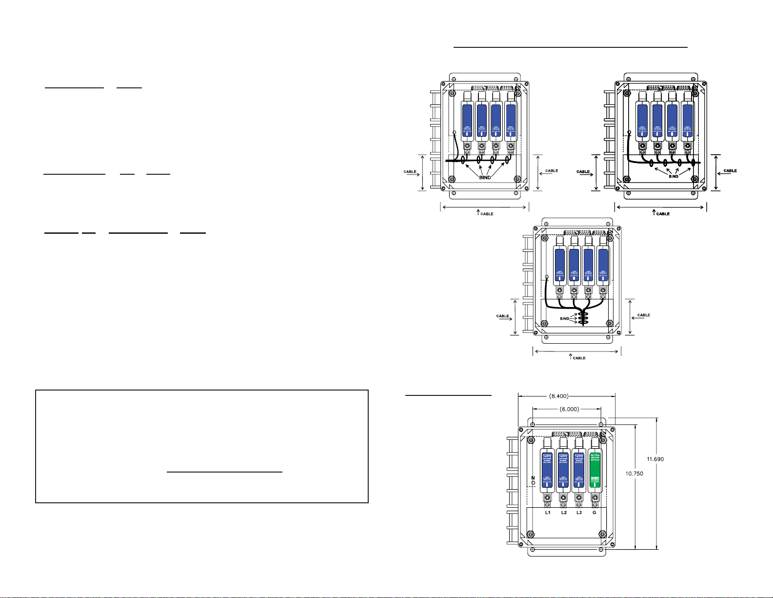
RECOMMENDED CABLE DRESSING
Each 10” (250mm) increase in cable length; increases clamping voltage by 25V per 1000A surge current discharged.
• BIND THE PHASE NEUTRAL AND GROUND
CONDUCTORS TIGHTLY, OVER THE ENTIRE RUN
FROM THE SUPPRESSOR TO THE SERVICE PANEL.
• ALWAYS USE THE SHORTEST LENGTH OF
CONNECTING CABLE POSSIBLE.
4 5
DIMENSIONS
Page 2
INTRODUCTION
60A
N
L2
L1
L1 L2
G
N
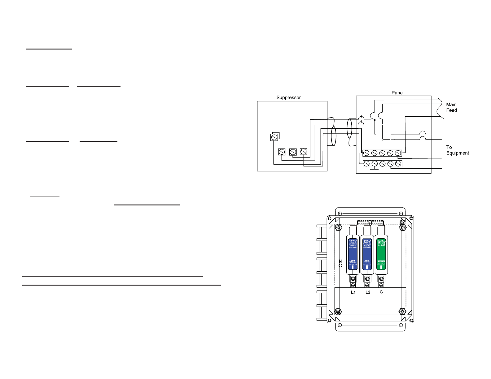
This document explains how to install the ZoneMaster Series of AC
Panel Surge Protective Devices.
INSTALLATION INSTRUCTIONS
Warning: T erminals marked L1, L2, L3, N, GND (where relevant) must
be connected respectively to phase(s) neutral and ground. Failure to
comply may result in danger or damage. See corresponding diagrams
for proper connections.
INSTALLATION DESCRIPTION
ZoneMaster units are connected in parallel (or in “shunt” across) the
supply to be protected. The connecting cable does not carry the supply current, only the current associated with suppressing the transient
overvoltage.
MOUNTING
The units should be mounted as close as possible to the panel to be
protected. See (page 4) on Connecting Lead lengths. Conduit, preferably
metallic, is to be installed from the suppressor to the panel. Drill holes
in the ZoneMaster enclosure only in the designated areas as shown in
recommended cable dressing illustrations (page 5). Mount the unit
in the appropriate location using the mounting holes provided on the
enclosure.
ZONEMASTER
Confi guration
and Schematic Connection Diagrams
120/240V SPLIT PHASE 3W
INCORRECT INSTALLATION WILL IMPAIR THE
EFFECTIVENESS OF THE AC PANEL PROTECTORS.
Particularly important is the length of the connecting leads (see
page 4).
2
7
Page 3
ZONEMASTER Confi guration
60A
N
L2
L1
L3
L1 L2
L3 G
N
and Schematic Connection Diagrams
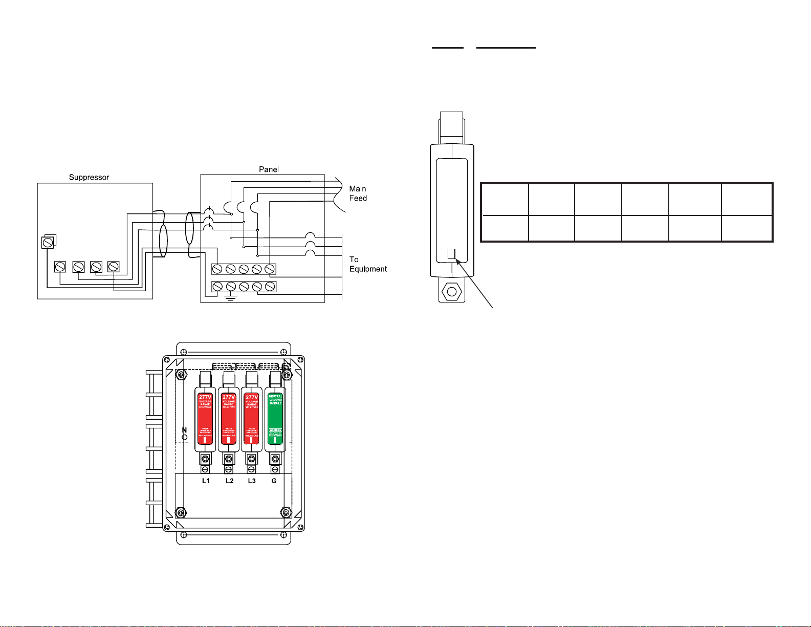
277/480 THREE PHASE 4W WYE
220/380 THREE PHASE 4W WYE
240/415 THREE PHASE 4W WYE
STATUS INDICATORS
The ZoneMaster units have comprehensive, continuous visual status
monitoring present on each module.
Status Full Reduced No No Power to High N-G
Indicated Protection (Standby) Protection Protector Voltage*
Present Protection
LED Green Red Red Green Red & Green
Indicator LED Lit LED Lit LED Lit LED Out LED Lit
Power/Protection
Indicator
REMOTE INDICATORS
A remote indication of the reduced protection state is available as a nor mally open or normally closed dry contact.
*WARNING: OF HIGH NEUTRAL TO GROUND VOLTAGE
On certain models, if both Red and Green lights are on, consult a qualifi ed
6
electrical contractor to check the integrity of the building wiring.
3
Page 4
MAINTENANCE
At intervals not exceeding two months, check:
1. Status indication lights
2. Conditions of connecting cables and terminals
Module Replacement
WARNING: Before opening the access panel,
ensure that the AC supply has been disconnected.
Unplug the remote contact connector at the top of the module. Remove
the mounting nuts at the top and bottom of the module. The protection
module can now be removed.
WARNING: Replace the defective module with a module
having the same color label and voltage rating.
Installation of the replacement module is the reverse of the above procedure. Final step, check that all cable connections are secure and
nuts are tightened. Do not overtighten.
NOTE: No customer serviceable parts inside. Opening
module WILL void Warranty
Copyright 1996© By Atlantic Scientifi c Corporation
All Rights Reserved
Printed in U.S.A.
For more information please contact your local MTL offi ce
or visit our web site at www.mtlsurge.com
Installation Instructions
& User Manual
ZONEMASTER SERIES
AC Panel Transient Voltage Surge Suppressors
The Americas: +1 800 835 7075
UK: +44 (0)1582 723633
Singapore: +65 6 487 7887
801482 Rev D 6/06/08
The Netherlands: +31 (0)481 450250
Italy: +39 (0)2 6180 2011
Australia: +61 (0)8 9455 2994
India: +91 (0)44 450 1660
 Loading...