

Page 1
CONGRATULATIONS! YOU HAVE JUST PURCHASED THE BEST SURGE PROTECTION IN
THE INDUSTRY!
Adhering to these instructions guarantees maximum performance of this Protection device.
IMPORTANT SAFETY INSTRUCTIONS CAUTION:
1. Never install telephone wiring during a lightning storm.
2. This product is intended for INDOOR USE ONLY.
3. Secondary Protectors are intended for use on the equipment side of a listed UL 497 Protector.
4. Primary Protectors are intended for use at the cable point of entry.
5. Risk of Electric Shock - Protector is not to be used without the arrestor assembly installed.
6. The Protector is a one or two pair Protector. Applications that use more will not function.
INSTALLATION
1. Read and understand all instructions.
2. The ZBS modules can be installed individually, mounting to any fl at surface using the two screw
holes. ZBS modules can also be installed on a Din Rail.
In planning an installation, location of the ZBS unit in close proximity to the correct ground point is essential
for protection performance. The correct ground point is defi ned as the ground reference used by the system
to be protected. In most applications this is AC power ground. MINIMIZE the distance between the ZBS
unit and the identifi ed ground point to the INCH.
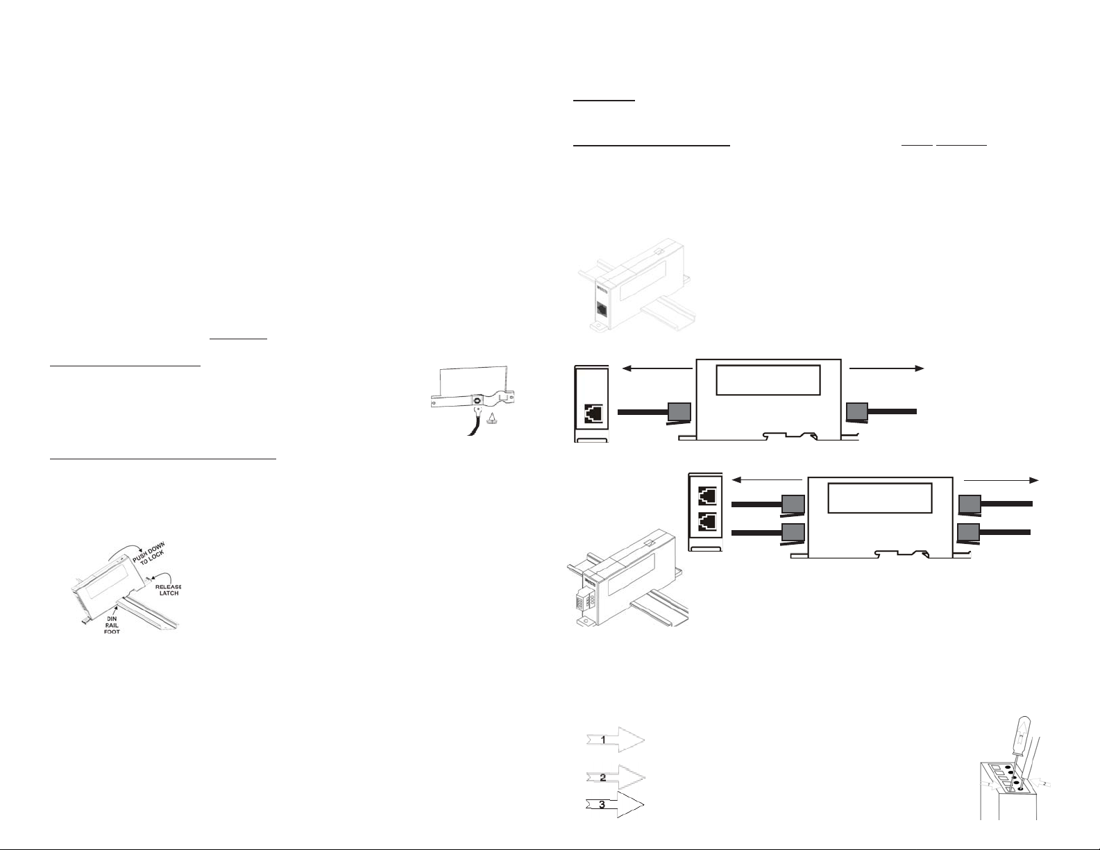
STAND-ALONE INSTALLATION
3. To install the ZBS unit as a stand-alone unit, attach a ground wire (minimum
#10 AWG for Primary Protector, minimum #14AWG for Secondary
Protector) to the ring terminal provided. Using the self tapping screw
provided, attach the ring terminal to the base of the unit. Using screws (or
bolts) as appropriate, mount the unit to the fl at surface (see fi gure 1).
Figure 1
MOUNTING AND GROUNDING ON A DIN RAIL
4. To install a ZBS surge protector on a Din Rail, locate the Din Rail foot over the Din Rail and
securely push the brass clip onto the Din Rail. Rotate downward and push the ZBS onto the Din
Rail until the latch snaps on to the rail. (see fi gure 2). To remove a module, gently pull the
release latch forward and rotate the ZBS upward off of the Din Rail. The surge protector is
now securely grounded to the Din Rail. An existing or customer supplied Din Rail can be
used providing the rail is securely connected to the correct ground (see grounding section).
Figure 2
module. Run cable from the ZBS port marked "protected" to the equipment to be protected. Additional instructions are provided below for connecting to terminal strips. Note: Always use the supplied patch cable
on the protected side of the suppressor. Patch cable wire size must not exceed #24AWG.
8. Connect a green ground wire from the Din Rail or from the ZBS unit to the identifi ed grounding
point (see grounding section). Primary Protectors require a minimum #10AWG, Secondary Protectors
require a minimum #14AWG.
5. The 19" Din Rail assembly can be mounted onto any surface using the
four mounting slots provided. The 19" Din Rail assembly will hold up
to 16 ZBS surge protectors. Use the same 19" Din Rail assembly for
19" rack mounting. The 5" Din Rail assembly is used for mounting up
to 4 ZBS surge protectors. Mount the rail to any surface using the two
mounting holes provided. NOTE: The Din Rail must be grounded, see
grounding section.
6. Any combination of ZBS modules can be employed as required.
7. Connect the incoming line to the port marked "unprotected" on the ZBS
9. CAUTION: the current limiting feature of telephone suppressors could be rendered
inoperable if the suppressor is improperly installed.
10. SAVE THESE INSTRUCTIONS.
GROUNDING:
The Din Rail grounding stud must be connected to the ground reference used by the system
being protected. In a computer room environment this grounding point may be the ground bar
in the AC power panel. Ground leads longer than 12" are not recommended.
W ARNING: The grounding lead must be as short as is practically possible. Minimize length
to the inch. The ground wire should be a minimum #14AWG for Secondary Protector applications and Primary Protector applications require a minimum #10AWG.
INDEPENDENT GROUNDS - Surge protection devices must not be connected to indepen-
dently derived grounds.
WIRING INSTRUCTIONS
All ZoneBarriers are clearly labeled with one end marked "Protected" and one end marked "Unprotected".
Connect fi eld cables to the unprotected side. Connect cables from equipment to be protected to the end
marked protected.
Models
RJ45/Coaxial Interface ZoneBarriers:
1. Simply connect the patch cable between the protected side of the
ZoneBarrier and the equipment to be protected.
2. Connect the fi eld cable to the unprotected side of the ZoneBarrier
3. NOTE: All RJ45 models universally accept RJ11 jacks
RJ45
To Field
To Equipment
Protected
Example: RJ45 Protector — ZB24540 illustrated
To Field
Protected
Unprotected
To Equipment
Example: RJ45 Protector — ZB24550 dual port illustrated
ZoneBarriers with Pluggable Headers:
Modules that use removable Terminal Strip connectors are keyed to
Fixed and Pluggable
Terminal Strip
All ZoneBarriers with CAGE CLAMP TERMINALS (fi xed and pluggable)
The cage clamp mechanism used on these modules offers THE MOST SECURE wire connection available. The quality of connection is signifi cantly better than standard screw terminals.
Insert a small screwdriver into the rectangular hole. Push screwdriver in and lever away from circular hole with moderate force.
This will open the wire cage clamp
Insert stripped wire into circular hole.
be inserted one way only. Do not force a connector into its header the
incorrect way.
Remove screwdriver. The wire is now secure.
Page 2
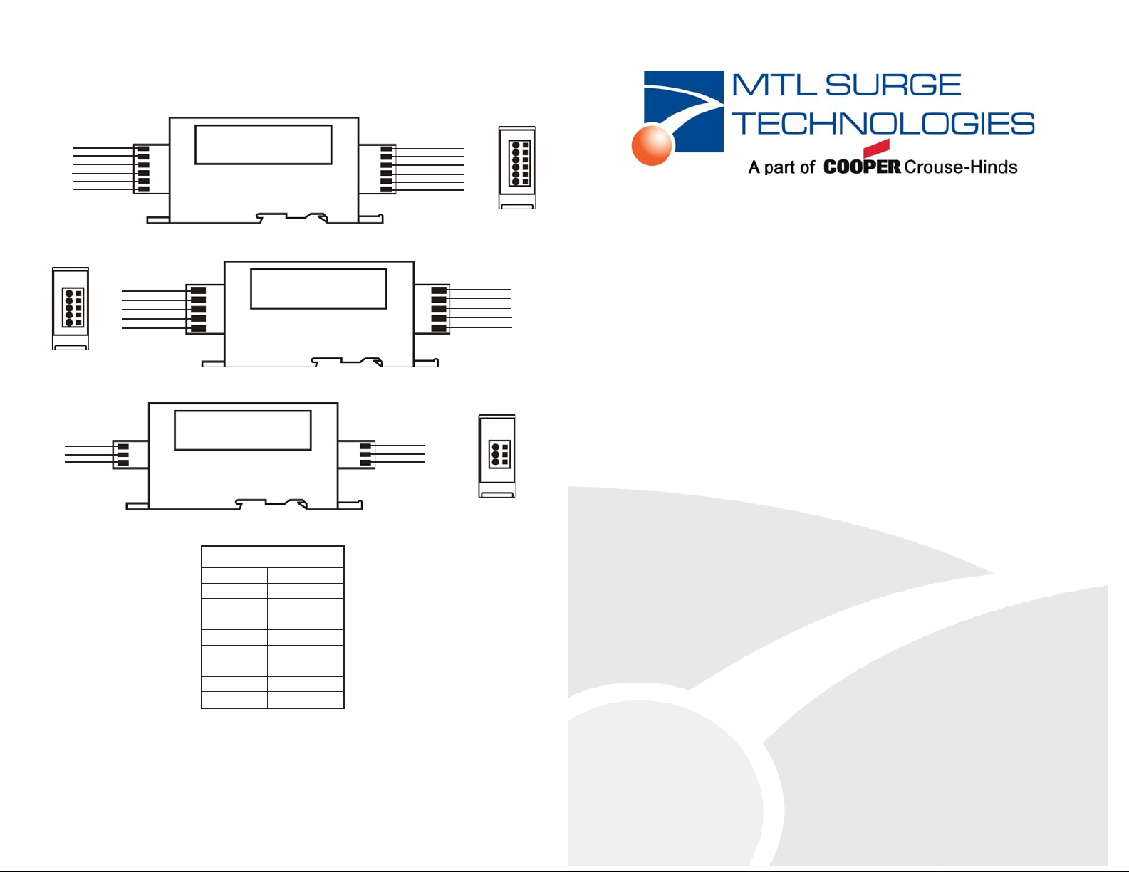
Cage Clamp Terminal Strip ZoneBarrier Models:
These models are available in 2-wire, 3-wire, 4-wire 5-wire and 6-wire versions. Each end of the ZoneBarrier is clearly marked with the terminals use (see below).
1. Connect fi eld wiring to the labeled terminals on the unprotected side of the ZoneBarrier.
2. Connect the equipment wiring to the correspondingly labeled terminals on the protected
side of the ZoneBarrier.
Protected
To Field
+ Pair 1
- Pair 1
+ Pair 2
- Pair 2
+ Pair 3
- Pair 3
212121
Unprotected
Example: 6-wire protector — ZB24542 illustrated
Signal wire 1
Signal wire 2
Signal wire 3
Signal wire 4
To Field
Shield
S4321
Unprotected
Example: 4-wire + shield protector — ZB24509 illustrated
Protected
Ground
To Field
-
+
1
2
G
Unprotected
21
G
Example: 2-wire + ground protector — ZB24518 illustrated
+ Pair 1
- Pair 1
+ Pair 2
- Pair 2
+ Pair 3
- Pair 3
212121
Protected
-
+
Ground
S4321
Equipment
To Protected
Equipment
To Protected
Signal wire 1
Signal wire 2
Signal wire 3
Signal wire 4
Shield
Equipment
To Protected
INSTALLATION
INSTRUCTIONS/
USER MANUAL
ZONEBARRIER SERIES
Din Rail Mount Protection System
Vbo Ratings
Useful information on
voltage ratings
ZB24528
ZB24543
ZB24544
ZB24545
ZB24546
ZB24558
ZB24588
ZB91264
ZB90651
6V
40 - 50V
40 - 55V
100 - 125V
20 - 25V
19 - 21V
19 - 21V
19 - 21V
60 - 80V
If devices are received damaged, please notify the transportation company. Please retain all
containers and packing materials for inspection.
Note: The protected device should also have AC suppression or it will still be vulnerable to
transients from the incoming AC power. This can show up as failures on the communication
interface.
For more information contact your local MTL rep:
www:mtlsurge.com/support/distribution/index.htm
801504 Rev B 12/4/08
 Loading...