

Page 1
Technical data
MTL surge protection
MTL TP32 range
Protects transmitters and
smart transmitters from
induced surges and transients
on fieldbus cabling
• TP32 is a fieldbus specific surge protector
designed to meet the requirements of IEC
61158-2:2004 & ANSI/ISA-50.02-2:1992
• TP32-T includes a terminator for fieldbus
in addition to surge protection
• Easy and direct mounting — screws into
spare conduit entry on the transmitter
• Parallel connection ensures ‘transparent’
operation — zero voltage-drop across device
• ATEX approved, Certified FISCO Terminator
• 10 year product warranty
July 2015
EPS 901-114 Rev L
The TP32 surge protection device is specifically designed to protect
process transmitters and devices on fieldbus systems. The TP32 builds
on the high specification of the acclaimed TP48 range to provide a level
of surge protection for fieldbus transmitters in excess of the optional
transient protection available from some transmitter manufacturers.
The terminated TP32-T has the same protection circuit as the
standard product, but also includes a F
circuit. This unique combination eliminates the need to purchase
and install additional termination circuitry for the FF segment. The
TP32-T provides excellent transient protection control and terminates
the bus segment in one simple-to-install package. The termination
circuit is designed to the requirements described in ANSI/ISA 50.02-2.
Note: Two terminators are required per bus segment.
The all-important earth connection is made via the casing of the
transmitter, negating the need for a separate earth connection or a
ground stake at the transmitter. In operation, the TP32 makes sure
that the transmitter electronics are never exposed to damaging
transients between the lines and ground. Any surge current appearing
as a series-mode or common-mode transient is converted into a
common-mode voltage whereupon the transmitter electronics are
temporarily raised to some higher voltage level before ‘floating’ down
automatically (and without damage) to resume normal operation.
1
oundation fieldbus™ termination
Measurement Technology Limited,
Great Marlings, Butterfield, Luton
Beds, LU2 8DL, UK.
Tel: + 44 (0)1582 723633 Fax: + 44 (0)1582 422283
E-mail: mtlenquiry@eaton.com
www.mtl-inst.com
© 2015 MTL
All Rights Reserved
Publication No. EPS 901-114 Rev L
July 2015
The TP32 protection network is a hybrid design consisting of highpower, solid state electronics and a gas discharge tube which is
capable of diverting surges up to 20kA. Encased in a 316 stainless
steel enclosure, the TP32 exhibits unparalleled mechanical durability
providing years of maintenance-free operation in harsh environments.
The enclosure is available threaded for all the common conduit entries.
Versions are available for 1/2” NPT, 20mm ISO, and G 1/2” (BSP 1/2
inch) threaded entries.
Installation is simple and can easily be carried out retrospectively
to existing installations. By connecting in parallel to the transmitter
circuit the TP32 does not interfere with the normal operation of the
bus – passing AC or DC signals without adding increased voltage drop
across the segment while consistently diverting surge currents safely
to ground and clamping output voltage to safe levels.
Approvals for intrinsically safe, flameproof, explosion-proof and
non-incendive operation are available, in all gas groups and apparatus
temperature classifications up to T6.
The TP32 is designed to meet the requirements of IEC 611582:2000 and ANSI/ISA-50.02-2:1992 for 31.25kB/sec systems as used
by Foundation fieldbus™, PROFIBUS-PA and WorldFIP.
Page 2
MTL TP32 range
July 2015
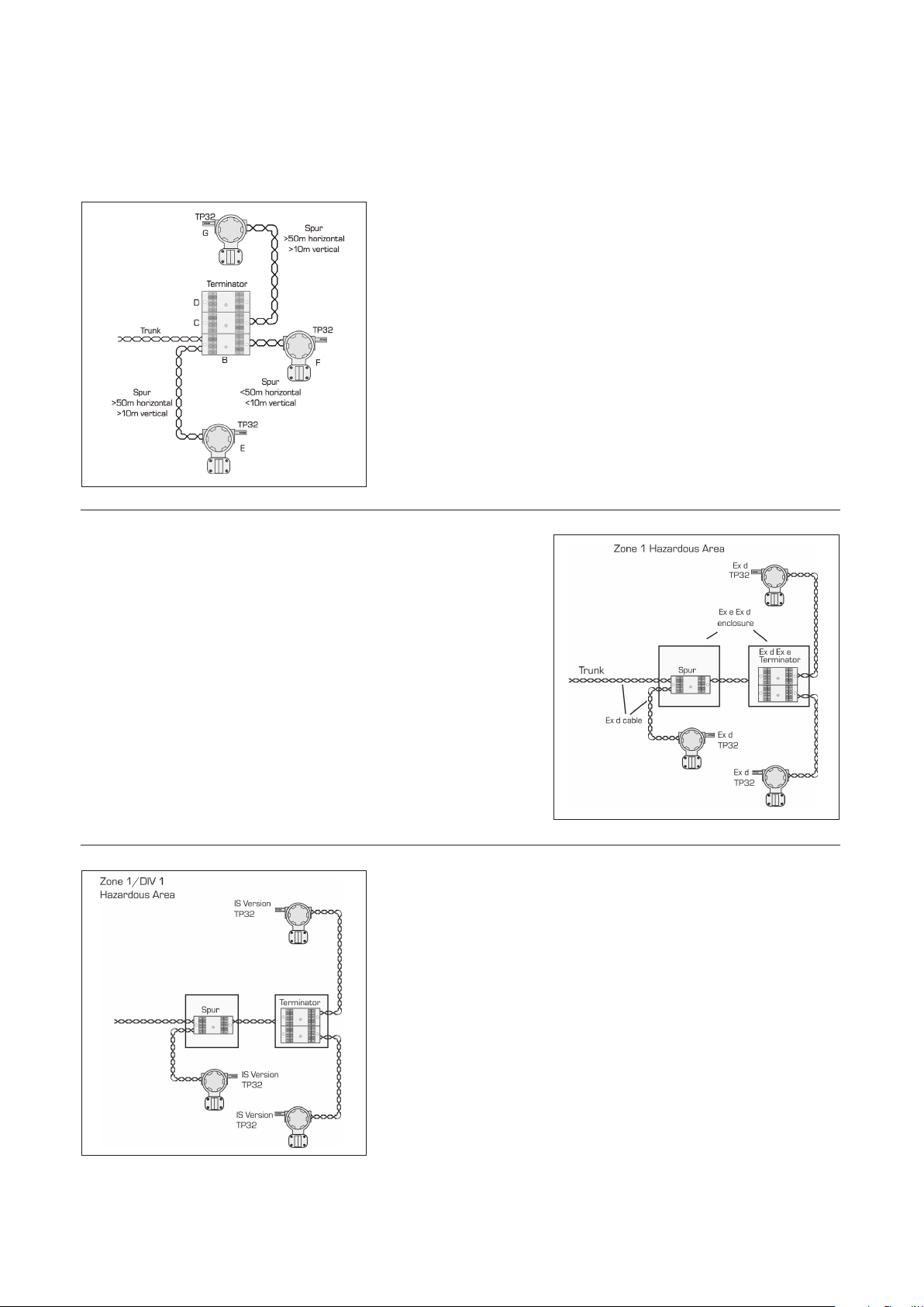
FIELD DEVICE PROTECTION USING TP32
Non-Hazardous Installation
Install a TP 32 on every instrument critical to the operation of the process
system.
Install TP 32 on each instrument with a spur length greater than 50m
horizontal and 10m vertical.
For a detailed risk analysis (to minimize the number of protectors required)
and guidance for total fieldbus system protection, please see TAN 1010.
Hazardous Area Explosion-proof, Flameproof / Increased Safety
Install TP 32-X-NDI (where X = thread t ype) on every instrument critical to
the operation of the process.
Install TP 32-X-NDI on each instrument with a spur length greater than 50m
horizontal, 10m vertical.
See TAN 1010 for details of total fieldbus protection.
Hazardous Area Intrinsically Safe System; FISCO
Install TP 32-X-NDI (where X = thread t ype) on every instrument critical to
the operation of the process.
Install TP 32-X-NDI on each instrument with a spur length greater than 50m
horizontal, 10m vertical.
See TAN 1010 for details of total fieldbus protection.
NOTE: The TP32 NDI is FISCO compatible.
NOTE: Protection at the host end of the trunk is mandatory, see FP32 datasheet and TAN 1010 for more information.
2
Page 3

MTL TP32 range
July 2015
USE OF THE TP32-T TO TERMINATE A FIELDBUS TRUNK
Conventional Installation
Installation Using TP32-T
Junction block and
terminator are required
at the far end of a
fieldbus trunk.
Use of TP32-T
eliminates the need for
an extra junction block
and terminator.
ORDERING INFORMATION
Model TP32 & TP32-T
Nominal voltage U
Rated voltage (MCOV) U
Nominal current I
Nominal discharge current (8/20µs) i
Max discharge current (8/20µs) I
Lightning impulse current (10/350µs) I
Residual voltage @ i
sn
Voltage protection level @ 1kV/µs U
Bandwidth f
n
sn
max
imp
U
G
n
c
p
p
Capacitance C 50pF
Series resistance R n/a
Operating temperature range -40°C to +60°C
Category tested A2, B2, C1, C2, C3, D1
Overstressed fault mode in=3kA 12k A
Impulse durability (8/20µs) 10k A
Degree of protection IP66
AC durability 1A
Service conditions 80kPa - 160kPa 5% - 95% RH
32V
35V
n/a
3kA
20kA
2.5kA
46V
<38V
7.5MHz
rms
, 5T
3
APPROVALS
Country (Authority) Standard No. Certificate/File Approved for Product
EC (BASEEFA) IEC 60079-0:2011
EC (BASEEFA) EN 60079-0:2009
ATEX Directive 94/9/EC EN 60079-0:2009
USA (FM)
Canada (FM) C22.2 No 213 (1987), C22.2 No 142 (1987),
Global IEC 60079-0:2004, IEC 60079-11:2006
EN 60079-11:2012
EN 60079-1:2007
EN 60079-15:2010
Class 3600 (1998), Class 3610 (2010),
Class 3611 (1999), Class 3615 (1989),
Class 3810 (1989) Incl Suppl #1 (1995)
ANSI/NEMA 250 (1991)
ISA-S12.0.01 (1998)
ANSI/ISA 60079-0 (2009)
ANSI/ISA 60079-11 (2009)
C22.2 No 94 (1991), C22.2 No 157 (1992),
C22.2 No 30 (1986)
ANSI/NEMA 250 (1991)
CAN/CSA-E79-0 (2002)
CAN/CSA-E79-11 (2002)
IEC 61241-0:2004, IEC 61241-1:2004
BASEEFA04ATEX0251X II 1G Ex ia IIC T4/T5/T6 Ga
BASEEFA04ATEX0053X II 2G Ex d IIC T6 (T
TML02ATEX0032X II 3 G Ex nA IIC T6 (-40°C<T
3011208 Intrinsically Safe:
3025374 Intrinsically Safe:
IECEx BAS 07.0045X Ex ia IIC T4/T5/T6
II 1D Ex ia IIIC T135°C/ T100°C/ T85°C Da
= -40°C TO +60°C) Gb
or T5 (T
or T4 (T
II 3 G Ex nA IIC T5 (-40°C<T
I, II, III/1/A-G, I/0/IIC
Explosion-proof: I/1/A-D
Non-incendive: I/2/A-D, I/2/IIC
Dust ignition proof: II,III/1/EFG
Special protection: II/2/FG
I, II, II/1/A-G, I/O/IIC
Explosion-proof: I/1/A-D
Non-incendive: I/2/A-D, I/2/IIC
Dust ignition proof: II, III/1/EFG
Special protection: II/2/FG
Ex tD A20 IP6X T85°C/T100°C/T135°C
amb
= -40°C TO +80°C) Gb
amb
= -40°C TO +85°C) Gb
amb
<+60°C)
amb
<+85°C)
amb
TP32-N-NDI
TP32-I-NDI
TP32-G-NDI
TP32-N-NDI
TP32-I-NDI
TP32-G-NDI
TP32-N
TP32-I
TP32-G
TP32-N-NDI
TP32-I-NDI
TP32-G-NDI
TP32 All
TP32-X-NDI
TP32-T-X-NDI
Page 4

MTL TP32 range
July 2015
SPECIFICATION
All figures typical at 25°C (77°F) unless
otherwise stated
Maximum surge current
20k A peak (8/ 20µs waveform)
Leakage current
Line-line: < 1µA at working voltage
Line-earth: < 1µA at 120V common-mode
Working voltage
±32V dc maximum
±120V peak (or DC) maximum common mode
Maximum continuous operating voltage
35V
Limiting voltage
Line-line with 25 0mm cable:
< 49V (10A , 10/1000µs pulse)
Line-earth with 75mm cable:
<635V (3kA, 8/2 0µs waveform)
<635V (6kV, 1.2/ 50µs waveform)
Line resistance
No resistance introduced into the loop
Capacitance
Line-line: < 50p F
Line-earth: < 100pF
Terminator (TP32-T only): 100 ohm, 1µF
Attenuation
7.8KHz–7.5MHz monotonic & better than
–1dB typical bandwidth, 150MHz on
100W system
Ambient temperature limits
T6: –40°C to +60°C (–40 °F to +14 0°F)
T5: – 40°C to + 85°C (– 40°F to +18 5°F)
Humidity
5% to 95% RH (non -condensing)
Electrical connections
3 flying leads: line 1 & line 2 plus nonpolarised earth
Wire size: 32 / 0.2 (1.0mm2, 18 AWG)
Lead length: 250mm minimum supplied
<75mm recommended
Casing
316 stainless steel suitable for harsh
environments
Threads
TP32-N: 1/2” NPT
TP32-I : 20mm ISO (M20 x 1.5)
TP32-G: G 1/2” (BSP 1/2 inch)
Weight
175 g (6.2oz)
Dimensions
See figure 1
ATEX compliance
See Approvals table for details
EMC compliance
BS EN 61643-1
Electrical Safety
EEx ia IIC T6, Ceq=0, Leq=0; the unit can be connected without further cer tification
into any intrinsically safe loop with open circuit voltage <30V and input power <1.2W.
EEx ia IIC T4, Ceq=0, Leq= 0; the unit can be connected into any FISCO application
with the following input parameters Pi= 5.32W.
EEx d IIC T6; the unit is apparatus-approved to explosion-proof (flameproof)
standards, and can be fitted into a similarly approved housing.
SIL INFORMATION
Failure rates according to IEC 61508
l
SD
TP32 0 FIT 12 FIT 5 FIT
The user of the TP range can utilize these failure rates in a probabilistic model of a safety
instrumented function (SIF) to determine the suitability in part for safety instrumented system
(SIS) usage in a particular safety integrity level. A full table of failure rates is presented in the
EXIDA report (section 4.4) along with all assumptions.
*The Residual Effect failures are included in the Safe Undetected failure category according to
IEC 61508. Note that these failures alone will not affect system reliability or safety and should
therefore not be included in spurious trip calculations.
Safe Failure Fraction needs to be calculated on (sub)system level.
A complete copy of the EXIDA report can be downloaded at www.mtl-inst.com.
Figure 2 Connection detail
for a typical process
transmitter
l
DD
l
DU
Figure 1 Dimensions
Positive
Negative
Earth
TO ORDER SPECIFY -
TP32 TP32-T
TP32-N TP32-T-N 1/2” NPT thread
TP32-N-NDI TP32-T-N-NDI 1/2” NPT thread, with EEx ia, EEx d, approval
TP32-I TP32-T-I 20mm ISO thread
TP32-I-NDI TP32-T-I-NDI 20mm ISO thread, with EEx ia, EEx d, approval
TP32-G TP32-T-G G 1/2” (BSP 1/2 inch)
TP32-G-NDI TP32-T-G-NDI G 1/2” (BSP 1/2 inch), with EEx ia, EEx d, approval
Measurement Technology Limited,
Great Marlings, Butterfield, Luton
Beds, LU2 8DL, UK.
Tel: + 44 (0)1582 723633 Fax: + 44 (0)1582 422283
E-mail: mtlenquiry@eaton.com
www.mtl-inst.com
© 2015 MTL
All Rights Reserved
Publication No. EPS 901-114 Rev L
July 2015
4
EUROPE (EMEA):
+44 (0)1582 723633
mtlenquiry@eaton.com
THE AMERICAS:
+1 800 835 7075
mtl-us-info@eaton.com
ASIA-PACIFIC:
+65 6 645 9888
sales.mtlsing@eaton.com
The given d ata is only intended as a p roduct
descrip tion and should not b e regarded as a legal
warrant y of properties or gu arantee. In the intere st
of further technical developments, we reserve the
right to make de sign changes.
 Loading...