

Page 1
• RangeofATEXCertifiedintrinsically
safesurgeprotectors
• Ultra-slimspace-savingdesign;easy
installation
• Multistagehybridprotectioncircuitry
–20kAmaximumsurgecurrent
• Rangeofvoltageratings–tosuitall
processI/Oapplications
• Highbandwidth,lowresistance,RTD,
PSTNand3-wiretransmitterversions
available
• 10yearproductwarranty
technical datasheet
SD Series
Ultra-slim user-friendly devices for protecting electronic equipment
and systems against surges on signal and I/O cabling.
The SD Series is a range of surge protection
devices combining unparalleled packing
densities, application versatility, proven
reliable hybrid circuitry, simple installation and
optional ‘loop disconnect’ facilities – features
which make the series the ultimate surge
protection solution for process equipment, I/O
systems and communications networks.
The exceptionally high packing densities
are the consequence of an ultra slim ‘footprint’
for individual modules which can thus ‘doubleup’ as feedback terminals. Each module
provides full hybrid surge protection for 2 and
3 wire loop protection.
Modules with a comprehensive range
of voltage ratings cover all process related
signals such as RTDs, THCs, 4 to 20mA loops,
telemetry outstations, shut-down systems and
fire and gas detectors.
Optional ‘loop disconnect’, is a feature
which allows commissioning and maintenance
to be carried out without removal of the surge
protection device. This facility is provided by
the SD07, SD16, SD32 and SD55 units. In
addition, a third connection on the field and
safe side of the protector is provided in order
to terminate screens safely.
For three wire applications the specially
designed SDRTD (Resistance Temperature
Detector) and the SD32T3, (for separately
powered 4-20mA loops) provide full 3-wire
protection in a single compact unit. The
recommended choice for the protection of
3-wire pressure transducers on low power
circuits is the SD07R3.
For higher bandwidth applications, the
SDR series has been developed to meet
the demands of today’s highest speed
communication systems.
120V and 240V AC versions are available
for I/O and power supplies up to three Amps
of load current and telephone networks can
be protected by the SDPSTN.
One simple manual operation clamps
modules securely onto DIN rail, which
automatically provides the essential highintegrity earth connection.
‘Top-hat’ (T-section) DIN rail is generally
suitable for mounting SD modules although
for adverse environments, a specially-plated
version is available. A comprehensive range of
mounting and earthing accessories can also
be supplied, see page 7 for further details.
901-107RevS220513
www.mtl-inst.com enquiry@mtl-inst.com
Page 2
Guide to applications and selection
The SD Series of SPDs includes models for almost all possible applications operating at voltages up to 250V AC. The optional ‘fuse/disconnect’
package provides both fused protection against fault currents and a convenient method of isolating field circuitry from protected circuitry without
needing additional disconnect terminals. The standard fuse (which is replaceable) is rated 250mA with 50mA fuses also being available by special
request. Where only the disconnect feature is required, solid links can be used.
As an example, this feature is of particular value in applications in which an SPD is used with a bulk power supply feeding multiple loops. The
individual module fuse prevents a fault or follow on current on one loop disrupting the power supply to the others. Also, loops can be removed from
the circuit for maintenance reasons or added without needing additional disconnect terminals.
The following guide to selection suggests the most suitable SDs for a number of specific applications. For technical information, see the detailed
specifications on the back page of this publication (some field circuit protection is shown for completeness).
FIELD CIRCUIT PROTECTED CIRCUIT
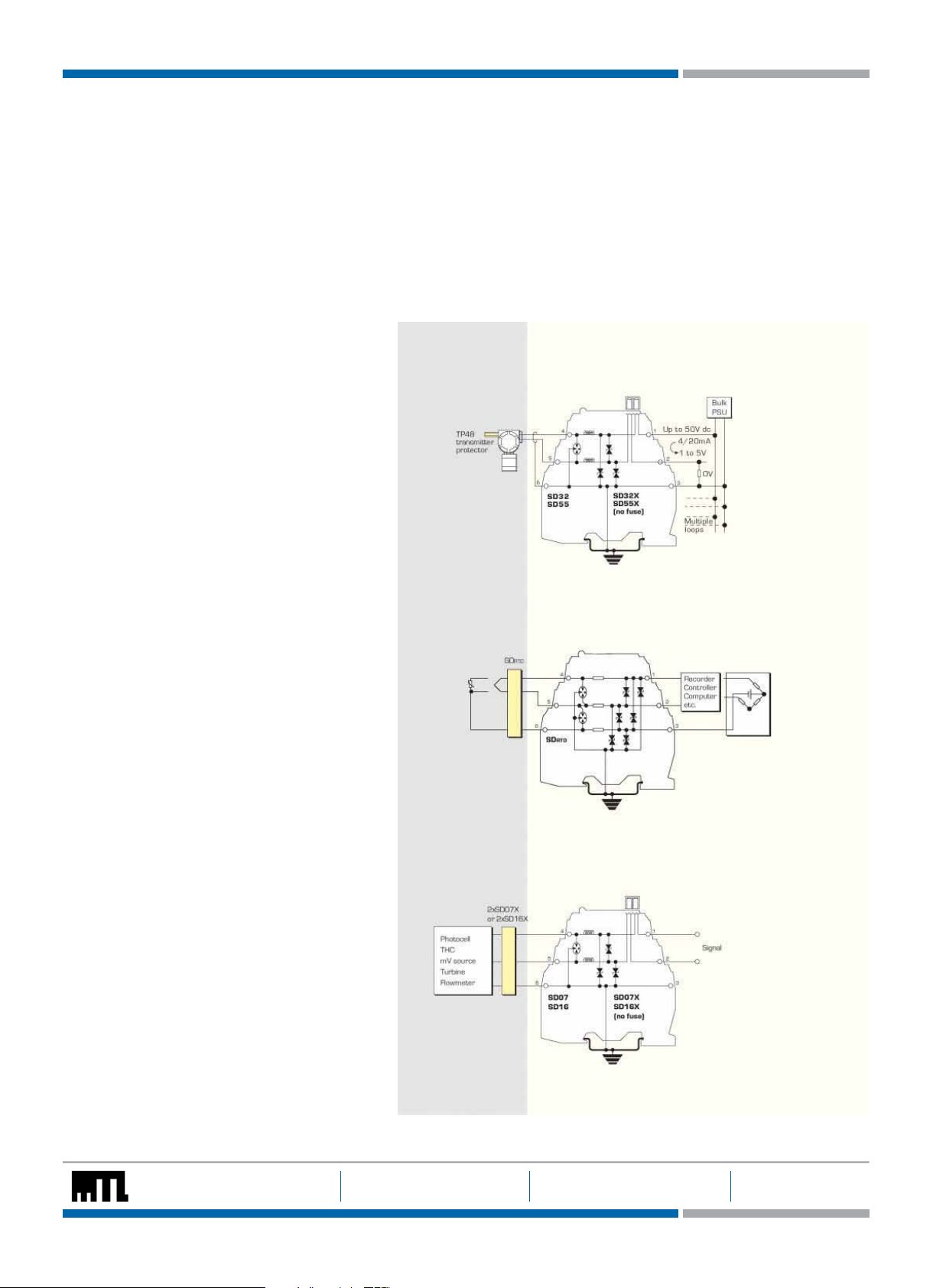
Analogue inputs (high-level)
2-wire transmitters, 4-20mA, conventional and
smart
The SPDs recommended for use with
‘conventional’ and ‘smar t’ 4-20mA transmitters
(fed by a well-regulated supply) are the SD32 and
SD55, the choice depending upon the maximum
working voltage of the system (32V and 55V
respectively). The diagram illustrates a prime
example of an application for which the fuse/
disconnect facility is particularly useful, however,
both models are available in ‘X’ versions without
the optional fuse/disconnect feature.
2-wire transmitters
Analogue inputs (low-level)
RTDs
These applications are best served using the
SDRTD. For optimum accuracy, the energising
current should be chosen to ensure the voltage
across the RTD does not exceed 1V over the full
measurement range. When using a PT100 device,
we recommend an energising current of 1mA.
Photocells, THCs, mV sources and turbine
flowmeters
The SD07 or SD16 (depending upon the
operational voltage) are the favoured choices
for this application. SD07X and SD16X are also
suitable.
3-wire RTDs
Photocells, THCs,
mV sources and
turbine flowmeters
The give n data is only inten ded as a product de scription an d should not be reg arded as a lega l warranty of pro perties
or guara ntee. In the i nterest of fu rther te chnica l develop ments, we re serve the r ight to make d esign cha nges.
EUROPE (EM EA): +44 (0 )1582 723633 THE AMER ICAS: +1 800 835 7075 ASIA-PACIF IC: +65 6 645 9 888
enquiry@mtl-inst.com csinfo@mtl-inst.com sales.mtlsing@cooperindustries.com 901-107 Rev S 220513
Page 3
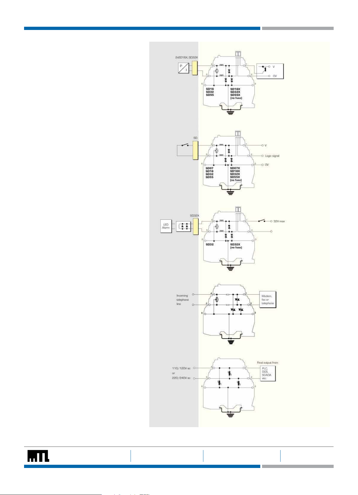
Analogue outputs
Controller outputs (I/P converters)
For this application, the recommendations are
the SD16, SD32 and SD55 (and the equivalent
‘X’ versions), the final choice depending upon the
operating voltage.
Digital (on/off) inputs
Switches
Suitable SPDs for switches include the SD07,
SD16, SD32 and SD55 modules – the choice depending upon the operating voltage of the system.
The ‘X’ versions of these are also suitable.
FIELD CIRCUIT
Controller outputs
(I/P converters)
Switches
PROTECTED CIRCUIT
Digital (on/off) outputs
Alarms, LEDs, solenoid valves, etc
The recommended choice for this application is
the SD32 or SD32X.
Telemetry (PSTN)
Telemetry outstations
The SDPSTN has been designed specifically for
the protection of signals transmitted on public
switched telephone networks.
AC supplied equipment
PLC, I/O systems
For systems on 110-120V ac, the SD150X is
the recommended choice and for 220-240V ac
systems, the SD275X is recommended.
Alarms, LEDs,
solenoid values,
etc.
Telecom line
PLC, I/O systems
The give n data is only inten ded as a product de scription an d should not be reg arded as a lega l warranty of pro perties
or guara ntee. In the i nterest of fu rther te chnica l develop ments, we re serve the r ight to make d esign cha nges.
EUROPE (EM EA): +44 (0 )1582 723633 THE AMER ICAS: +1 800 835 7075 ASIA-PACIF IC: +65 6 645 9 888
enquiry@mtl-inst.com csinfo@mtl-inst.com sales.mtlsing@cooperindustries.com 901-107 Rev S 220513
Page 4

Transmitter and sensor protection
Transmitters and sensors are widely used in highly exposed areas and where lightning damage is common. In many cases, the ideal solution for
2-wire transmitters or sensors is the TP48 which mounts directly onto the transmitter housing via spare cable entries. Where these entries are
not available or 3-wire devices are used, the compact design and simple installation of the SD series makes it the obvious choice for transmitter
protection.
The SDs within the junction box should be installed no fur ther than one metre away but as close as possible to the sensor or transmitter they are
protecting. A bond is required from the general mass of steelwork to the sensor or transmitter housing either using a flat short braid or a cable of at
least 4mm2 cross sectional area. In most instances this bond is automatically made by fixing the metallic transmitter housing to the plant structure.
This bond ensures the voltage difference between the signal conductors and the transmitter housing is below the transmitter’s insulation rating.
Please note that the transmitters or sensors are connected to the ‘Protected Equipment’ terminals of the SD and not the ‘Field Cables’.
TO HOST CIRCUITSD PROTECTED FIELD CIRCUIT
2-wire transmitters or sensors
4-20mA transmitters, conventional and smart
Where the TP48 is not an acceptable solution,
either because of technical suitability or difficulties
in mounting, the SD16X, SD32X and SD55X are an
excellent alternative.
2-wire transmitter or sensor
3-wire transmitters or sensors
Vibration Sensors and 4-20mA loop process
control systems invariably require three wire
connections, when powered from an external
source.
This may be accomplished in one unit by using the
SD32T3 three terminal Surge Protection Device
(SPD).
Because the SD32T3 protects all three conductors
within the same unit, higher protection is achieved,
as the SPD hybrid circuitry is common to all three
wires.
The SD07R3 is available for the protection of
3-wire pressure transducers on low power circuits.
3-wire transmitter or sensor
4-wire transmitters or sensors
Flow meters, level detectors, etc.
4-wire systems such as level detectors require
two SDs, one for the supply and the other for the
transmitter output. Generally the voltages across
the pairs are similar and so the recommended
choice would be a pair of SD16X, SD32X or
SD55Xs. However, mains powered transmitters
should be protected with an SD150X or 275X
(depending upon supply voltage) for the supply
inputs.
Loadcells are catered for by MTL Surge
Technologies’ LC30 which is suitable for both 4and 6-wire load cells.
EUROPE (EM EA): +44 (0 )1582 723633 THE AMER ICAS: +1 800 835 7075 ASIA-PACIF IC: +65 6 645 9 888
enquiry@mtl-inst.com csinfo@mtl-inst.com sales.mtlsing@cooperindustries.com 901-107 Rev S 220513
4-wire transmitter or sensor
The give n data is only inten ded as a product de scription an d should not be reg arded as a lega l warranty of pro perties
or guara ntee. In the i nterest of fu rther te chnica l develop ments, we re serve the r ight to make d esign cha nges.
Page 5

Communication systems protection
High speed data links between buildings or one part of a plant to another have become more common with the widespread use of smart transmitters
and the increase in unmanned installations. The SD series has an SPD suitable for all process I/O applications with a choice of low resistance units,
high bandwidth and a variety of voltage variants. The SDR series has been specially designed to meet the requirements for high speed data links
with an extremely high bandwidth.
Communication systems
RS232, RS422, RS485
The recommended choice for these applications is
the SD16R or SD32R depending on the maximum
driver signal.
Bus powered systems
There are a variety of bus powered systems
specially designed for the process industry. The
ideal surge protection device for these systems is
the SD32R as it has a very high bandwidth and a
modest in-line resistance.
TP PROTECTED
FIELD CIRCUIT
RS232, RS422,
RS485
PROTECTED FIELD CIRCUIT
SD PROTECTED
HOST CIRCUIT
SD PROTECTED
HOST CIRCUIT
Typical Applications
Table 1 shows suitable SD devices for different
applications. In some applications alternative
devices may be used, for example, where lower
in-line resistance or a higher voltage power supply
is used.
MTL Surge Technologies has operationally tested
the recommended SD series with representative
highways listed but no formal approval for their
use in systems by the respective bodies has been
sought.
Bus powered systems
Table 1
Application Preferred SPD Alternative
Allen Bradley Data Highway Plus SD16R
Foundation Fieldbus
31.25kbits/s voltage mode
1.0/2.5 Mbits/s
HART SD32X SD32, SD32R
Honeywell DE SD32X SD32, SD32R
LonWorks
FFT-10
LPT-10
TP-78
IS78†
Modbus ‘& Modbus Plus (RS485) SD16R
PROFIBUS
DP
PA (IEC 1158, 31.25 kbits/s)
RS232 SD16 SD16X
RS422 SD07R
RS423 SD07R
RS485 SD07R
WorldRP (IEC 1158)
31.25 kbits/s voltage mode
1.0/2.5 Mbits/s
The give n data is only inten ded as a product de scription an d should not be reg arded as a lega l warranty of pro perties
or guara ntee. In the i nterest of fu rther te chnica l develop ments, we re serve the r ight to make d esign cha nges.
SD32R
SD55R
SD32R
SD55R
SD07R
SD32R
SD32R
SD32R
SD32R
SD55R
EUROPE (EM EA): +44 (0 )1582 723633 THE AMER ICAS: +1 800 835 7075 ASIA-PACIF IC: +65 6 645 9 888
enquiry@mtl-inst.com csinfo@mtl-inst.com sales.mtlsing@cooperindustries.com 901-107 Rev S 220513
Page 6

Hazardous area applications
Zone 0/Zone 1
The dangers from lightning induced sparking
in Zone 0 are considered real enough to
require preventative measures. IEC 60079-14
(1996-12) Electrical apparatus for explosive
gas atmospheres Part 14: Electrical
installations in hazardous areas (other than
mines) stresses the importance of SPDs in
hazardous areas. An outdoor installation,
where there is a high likelihood of both
lightning induced transients and combustible
gases, requires the installation of SPDs to
prevent possible ignition of the gases. Areas
seen particularly at risk include flammable
liquid storage tanks, effluent treatment
plants, distillation columns in petrochemical
works and gas pipelines.
SPDs for transmitter protection should be
installed in Zone 1 but sufficiently close to
the Zone 0 boundary to prevent high voltages
entering Zone 0. The distance from the SPD to
Zone 0 should be less than one metre where
possible. However, in practice the SPD would
normally be mounted on the transmitter or
sensor housing which usually lies in Zone 1
and is very close to Zone 0. Because there is
only a very small free volume, the SD Series
is suitable for mounting in flameproof or
explosion proof enclosures.
The power rating for each of these is dependent on the table shown below.
= 1W (–30°C to +75°C)
P
i
P
= 1.2W (–30°C to +60°C)
i
= 1.3W (–30°C to +40°C)
P
i
The SD** Series are classified as simple apparatus and are intended for use in Zone 2 or safe
areas only, because their fuses are not fully encapsulated.
Installation
Positioning
The SDs should be mounted on the field wiring side to ensure that any surges entering from
the field do not damage any intrinsically safe barriers or galvanic isolators in the system.
The SDs and IS interfaces should be mounted close to each other but on separate DIN rails
in order to maintain the required 50mm clearance between safe area and hazardous area
terminals.
Zone 2
The SD series is suitable for protecting
electrical circuits in Division 2, Zone 2 and
can be used without affecting the safety
aspects of the circuit. Non-incendive (lowcurrent) circuits can be protected using any
SD series unit mounted in either the safe or
hazardous area including those with the fuse
disconnect facility. Non arcing (high current)
circuits can also be protected except that
SPDs with the fuse disconnect facility may
only be mounted in the safe area. For use in
these circuits the units must be mounted in
a suitable enclosure, normally the minimum
requirements are IP54 and 7Nm resistance to
impact. The SD series is self-certified by MTL
Surge Technologies as being suitable for this
purpose.
Certification
Introducing surge protection into Intrinsically
Safe (IS) circuits is trouble free as long as
the current and power parameters are not
exceeded. In the SD Series, the SD**X, SD**R,
SD**R3, SDRTD and SD**T3 all have ATEX
certification for use in IS circuits located in
Zones 0, 1 or 2. The certification parameters
for the SD**X and SD**T3 are:
Ex ia IIC T4 Ga, Li = 0.22mH
= 260mA for Ui up to 20V
I
i
= 175mA for Ui up to 26V
I
i
Ii = 140mA for Ui up to 28V
I
= 65mA for Ui up to 60V
i
The certification parameters for the SD**R,
SD**R3 and SDRTD are:
Ex ia IIC T4 Ga, Li = 0
= 260mA for Ui up to 60V
I
i
Earthing
The recommended earthing for field mounted devices has been illustrated previously but it is
the earthing at the control panel that is more critical as there are usually a number of earthing
systems, each with their own requirements. The earthing system illustrated here replaces
the instrument 0V bond, the control system PSU bond and the IS earth with one single earth
connection to meet all the design requirements and give the most ef fective protection against
the effects of lightning induced surges.
The give n data is only inten ded as a product de scription an d should not be reg arded as a lega l warranty of pro perties
or guara ntee. In the i nterest of fu rther te chnica l develop ments, we re serve the r ight to make d esign cha nges.
EUROPE (EM EA): +44 (0 )1582 723633 THE AMER ICAS: +1 800 835 7075 ASIA-PACIF IC: +65 6 645 9 888
enquiry@mtl-inst.com csinfo@mtl-inst.com sales.mtlsing@cooperindustries.com 901-107 Rev S 220513
Page 7
SD Series mounting kits and accessories
The SD Series has a full range of mounting kits and accessories to simplify installation and tagging of individual loops. Insulating spacers (ISP7000)
are available to allow mounting of the units onto backplanes without compromising correct earthing practice. These are placed at regular intervals
along the rail or at each end as required. Ear th connections can be made to the DIN rail via the earth terminal (ETL7000). Weatherproof enclosures
are also available with all the necessary mounting accessories to install the SD series surge protection devices.
Two tagging systems are available. One consists of tagging strips (TAG57) with labels (TGL57) mounted on posts (IMB57) at each end of a row
of surge protection devices (SPDs). The other consists of separate tagging identifiers (BRI7000) mounted on the tops of individual SPDs. Both
methods can be used conjointly. Replaceable fuses or solid links are available in packs of 5 (SD-F25, SD-F05 and SD-LNK).
Mounting accessories
ISP7000 Insulating spacer
THR2 Standard DIN rail, 35mm x 7.5mm
THR7000 T-section DIN rail, specially nickel plated,
35mm x 7.5mm, 1m length
Earthing/earth rail accessories
ETL7000 Earth terminal, DIN rail mounted
IMB57 Insulated mounting block (two needed)
ERB57S Earth rail bracket, straight
ERB57O Earth rail bracket, offset
ERL7 Earth rail, 1m length
ETM7 Earth terminal, pack of 50
Tagging accessories
TAG57 Tagging strip, 1m length
TGL57 Tagging strip labels, set of 10 x 0.5m
BRI7000 Barrier identifier
BIL7000 Barrier identification labels, sheet of 120
BIL7000L Barrier identification labels, A4 sheet of 126
Enclosures
DX070 Enclosure for up to 9 x SD series SPDs
DX170 Enclosure for up to 22 x SD series SPDs
DX430 Enclosure for up to 58 x SD series SPDs
Accessories (replacement)
SD-F25 Replaceable fuse pack - 250mA standard
(available in packs of 5)
RLA7050 Replaceable fuse pack - 50mA special
(available in packs of 5)
RLA7000 Solid Link (available in packs of 5)
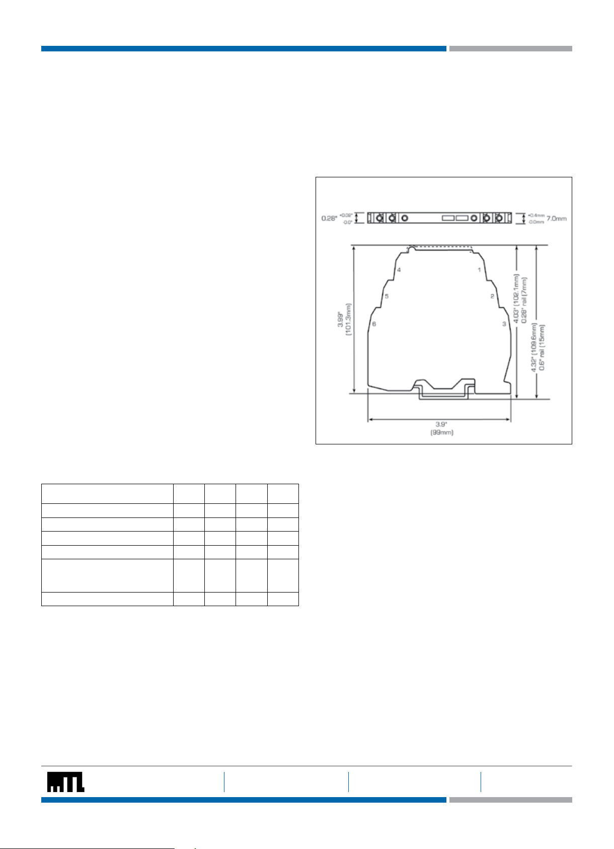
DIMENSIONS
SIL information
Failure rates according to IEC 61508
lSD lSU* lDD lDU
SD07,SD16,SD32,SD55 0FIT 75FIT 15FIT 2FIT
SD07R,SD16R,SD32R,SD55R 0FIT 46FIT 15FIT 2FIT
SD07X,SD16X,SD32X,SD55X 0FIT 47FIT 15FIT 2FIT
SD07R3,SD07T3,SD07X3 0FIT 73FIT 20FIT 7FIT
SD16R3,SD16T3,SD16X3,SD32R3,
SD32T3,SD32X3,SD55R3,SD55T3,
SD55X3
SDRTD 0FIT 71FIT 20FIT 9FIT
The user of the SD Series can utilize these failure rates in a probabilistic
model of a safety instrumented function (SIF) to determine the suitability
in part for safety instrumented system (SIS) usage in a particular safety
integrity level. A full table of failure rates in presented in the EXIDA
report (section 4.4) along with all assumptions.
*The Residual Effect failures are included in the Safe Undetected
failure category according to IEC 61508. Note that these failures alone
will not affect system reliability or safety and should therefore not be
included in spurious trip calculations.
Safe Failure Fraction needs to be calculated on (sub)system level.
A complete copy of the EXIDA report can be downloaded at www.
mtlsurge.com.
0FIT 72FIT 18FIT 6FIT
Definitions of terminology used in table on page 8.
1. Working voltage (Un)
Maximum voltage between lines or lines/ground for the specified
leakage current
2. Maximum leakage current (Ic)
Maximum current drawn by the SPD at the working voltage
3. Maximum continuous operating voltage (Uc)
Maximum voltage that can be applied to the protected terminals
without damage
4. Voltage protection level (Up)
Peak output voltage after injection of test impulse from 1kV/µs
generator (often known as ‘let-through’ voltage)
5. Bandwidth
Frequency range up to which ac signals can be transmitted without
undue attenuation; 3dB into 50W (600W for the SDPSTN)
The give n data is only inten ded as a product de scription an d should not be reg arded as a lega l warranty of pro perties
or guara ntee. In the i nterest of fu rther te chnica l develop ments, we re serve the r ight to make d esign cha nges.
EUROPE (EM EA): +44 (0 )1582 723633 THE AMER ICAS: +1 800 835 7075 ASIA-PACIF IC: +65 6 645 9 888
enquiry@mtl-inst.com csinfo@mtl-inst.com sales.mtlsing@cooperindustries.com 901-107 Rev S 220513
Page 8

SPECIFICATION
All figures typical at 77°F (25°C) unless other wise stated
Protection
Full hybrid line to line
Each line to screen/ground
Max discharge surge current (I
20kA (8/20 µs)
6.5kA (SD150X and SD275X only)
Nominal discharge surge current (i
3kA (8/20µs)
Lightning impulse current (I
2.8k A
1.0kA (SD150X and SD275X only)
Response time
<1ns
RTD resistance range (SDRTD)
10 to 1500W
Degradation accuracy (SDRTD at 1mA)
0.1% (RTD resistance > 100W )
0.1W (RTD resistance < 100W)
Ambient temperature
–40°C to +80°C / -40°F to 176°F storage
–40°C to +80°C / -40°F to 176°F working
For IS working applications:
= 1.0W (–30°C to +75°C / -22°F to 167°F)
P
i
Pi = 1.2W (–30°C to +60°C / -22°F to 140°F )
Pi = 1.3W (–30°C to +40°C / -22°F to 104°F)
Humidity
5 to 95% RH (non-condensing)
Category tested
A2, B2, C1, C2, C3
Overstressed fault mode in=3kA
12k A
9kA (SD150X and SD275X only)
Impulse durability (8/20µs)
10k A
6.5kA (SD150X and SD275X only)
Terminals
2.5mm
2
(12 AW G)
Mounting
T-section DIN-rail 35 x 7.5 or 35 x 15mm rail
(1.38” x 0.3” x 0.6”)
Weight
70g approximately (2.5oz)
Case flammability
UL94 V-2
AC durability
, 5T
1A
rms
Service conditions
80kPa - 160kPa
5% - 95% RH
EMC compliance
To Generic Immunity Standards,
EN 61326-1, part 2 for industrial environments
R&TTE compliance
EN 61326-1, EN 41003 : 1999
EN 60950 - 1 : 20 06
(not applicable to SD150X and SD275X)
LVD compliance
SD150X & SD275X
EN 60950 - 1 : 20 06, EN 61010 : 2010
SDPST
EN 41003 : 1999
IEC compliance
EN 61643-21:2001
ANSI/IEEE testing
C62.41-1-20 02
C62.41-2-2002
C62.45-2002
To order -
Order by module, as listed in the
specification table and/or accessory
part numbers, as defined on page 7.
max
) (10/350µs)
imp
) (8/20µs)
)
sn
Model Nominal
voltage+
(Vdc)(Vac)
Nominal
current
)
(U
n
(mA)
SD07 7 5 250 4.2† 500 7.7 <12 30 25kHz
SD16 16 11 250 4.2† 5 17 <25 40 25kHz
SD32 32 22 250 4.2† 5 36 <45 60 25kHz
SD55 55 38 250 4.2† 5 62 <90 100 25kHz
SD07R 7 5 400 2.7 500 7.7 <12 30 50MHz
SD16R 16 11 400 4.7 5 17 <25 40 50MHz
SD32R 32 22 400 10 5 36 <45 60 50MHz
SD55R 55 38 400 10 5 62 <90 100 50MHz
SD07X 7 5 400 2.2 500 7.7 <12 30 25kHz
SD16X 16 11 400 2.2 5 17 <25 40 25kHz
SD32X 32 22 400 2.2 5 36 <45 60 25kHz
SD55X 55 38 400 2.2 5 62 <90 100 25kHz
SD32T3 32 22 400 2.2
SD07R3 7 5 400 2.7 500 7.7 <12 30 50MHz
SD16R3 16 11 400 4.7 5 17 <25 40 50MHz
SD32R3 32 22 400 10 5 36 <45 60 50MHz
SD55R3 55 38 400 10 5 62 <90 100 50MHz
SDRTD 1 0.75 10< 2.7 0.3 5 <12 38 50MHz
(In)
Series
resistance
(W/line)
^
Max.
leakage
current
(µA)
Rated
voltage
*MCOV)
(Uc)
Voltage
protection
level(Up)
@1kV/µs
Residual
voltage
Bandwidth
(frequency)
@i
(V)
sn
(V)
5 36 <45 75 720kHz
f
G)
(
Special
feature
Fuse disconnect
Fuse disconnect
Fuse disconnect
Fuse disconnect
High bandwidth
High bandwidth
High bandwidth
High bandwidth
Low resistance
Low resistance
Low resistance
Low resistance
3 Terminal
3 Terminal
3 Terminal
3 Terminal
3 Terminal
3-wire RTD
SDPSTN 162 114 550 4.7 5 175 <200 235 4MHz PSTN
ac
rms
SD150X 150 120 3A‡ 0.1 50 170 130 <400 450 ——
SD275X 320 240 3A‡ 0.1 50 360 275 <700 850 ——
ac
dc
rms
High current
High current
Note: all figures are typical at +25°C unless otherwise stated; *standard fuse; +over full working temperature
range; †at 20mA with a 250mA standard fuse; ‡these units ne ed external 3A fuses; ^Signal; **Power &
Common; <maximum energizing current depends upon RTD resistance. See page 2 for details.
Products highlighted in blue are ATEX certified Ex ia IIC T4 Ga.
Approvals
Authority
(Country)
Baseefa [ATEX]
(EU)
MTL
(EU)
Baseefa [IECEx]
(International)
CSA/C/US
(Canada, USA)
UL
(USA)
Austel
(Australia)
Standard Certificate/
Approved for Product
File No.
EN 60079-0:2009
EN 60079-11:2007
Baseefa02ATEX0211X Ex ia IIC T4 Ga
Ta = -30°C to See
Schedule
EN 60079-15:2005
MTL03ATEX0755X Ex nA IIC T4 SD07, SD16, SD32, SD55, SD07X, SD16X,
EN 60079-14:2003
IEC 60079-0: 2007-10
IECEx BAS 12.0003X Ex ia IIC T4 Ga SD07X, SD16X, SD32X, SD55X, SD07R,
IEC 60079-11: 2006
CSA C22.2 No. 0-M1991
CSA C22.2 No. 157-M1992
UL 913, 5th edition
CSA C22.2 No. 142-M1987
CSA C22.2 No. 213-M1987
LR 36637 EEx ia Class 1,
Groups A, B
C and D, T4
Class 1, Div 2
Groups A,B,C, D T4
UL 497B Listed E220693 Isolated loop com-
munication circuits
AS/NZ3548:1995
__ Private Wire SD07R
AS/NZS4117:1996
TS001: 1997
SD07X, SD16X, SD32X, SD55X,
SD07R, SD16R, SD32R, SD55R,
SDRTD, SD32T3, SD07R3, SD16R3,
SD32R3, SD55R3
SD32X, SD55X, SD07R, SD16R, SD32R,
SD55R, SD32T3, SD07R3, SD16R3,
SD32R3, SD55R3, SDRTD
SD16R, SD32R, SD55R, SDRTD, SD32T3,
SD07R3, SD16R3, SD32R3, SD55R3
SD07, SD16, SD32, SD55, SD07X,
SD16X, SD32X, SD55X, SD07R,
SD16R, SD32R, SD55R, SDRTD,
SD32T3, SD07R3, SD16R3, SD32R3,
SD55R3
SD07, SD16, SD32, SD55, SD07X,
SD16X, SD32X, SD55X, SD07R,
SD16R, SD32R, SD55R, SD07R3, SD16R3,
SD32R3, SD55R3, SD32T3, SD55T3,
SD07X3, SD16X3, SD32X3, SD55X3,
SDRTD
The give n data is only inten ded as a product de scription an d should not be reg arded as a lega l warranty of pro perties
or guara ntee. In the i nterest of fu rther te chnica l develop ments, we re serve the r ight to make d esign cha nges.
EUROPE (EM EA): +44 (0 )1582 723633 THE AMER ICAS: +1 800 835 7075 ASIA-PACIF IC: +65 6 645 9 888
enquiry@mtl-inst.com csinfo@mtl-inst.com sales.mtlsing@cooperindustries.com 901-107 Rev S 220513
 Loading...