

Page 1

ultra-slim safety
barriers that can be
used like terminals
MTL7000 SERIES
MTL7000 Series award-winning,
intrinsic safety shunt-diode safety barriers
are innovative devices designed to provide
exceptionally high packing densities, straightforward
‘single-operation’ installation and simplified
connection, commissioning and maintenance
facilities. Many of the MTL7000 Series features
duplicate the functions of conventional field terminals
and the barriers can, therefore, ‘double up’ as
terminals for many applications, saving even more
space.
A barrier width of only 7mm enables
maximum packing densities due to the use of surface
mount and thick-film hybrid circuit technologies
(subjects of patent applications).
Barrier identification is provided by one or both
of two methods. The first consists of tagging strips
mounted on posts located at each end of a row of
barriers while the other consists of separate
identifiers attached to the tops of individual barriers.
Of these, the first can be used to tag locations as well
as barriers and is recommended for large
installations while the second is better suited to
installations of a few barriers only.
An optional power comb simplifies
installations where multiple barriers are powered
from a common 24V dc source (via a power feed
module or a dummy barrier). The comb replaces
individual power supply connections to each barrier,
yet allows single barriers to be removed without
affecting the others. The power feed module powers
up to 40 barriers and incorporates a trip which
switches off the supply to the barriers if a fault (such
as an overvoltage) occurs in the power source
circuit.
Secondary replaceable fuse versions of
many barriers are available and form the
MTL7100 sub-series. These are useful where there is
a possibility of faults occurring during commissioning
which would otherwise blow the barriers' internal
safety fuses. One secondary replaceable fuse for
each barrier channel is provided and is lower in
value than the related safety fuse. Fuses are
packaged in small mouldings which can be latched
in a 'disconnect' position to break the safe and
hazardous areas during commissioning,
maintenance or fault finding, thus avoiding the need
for additional disconnect terminals.
Where a fuse is less likely to be
necessary, the MTL7200 sub-series uses a latching-
out link only, to provide the basic loop disconnection
of the MTL7100 sub-series.
◆
Direct connection of cable screens
and 0V lines – third terminal on
both hazardous and safe sides
◆ Patent US 5838547
◆ Exceptionally high packing
densities – only 7mm barrier width
◆ 24V dc supply connections
simplified – optional power comb
feeds many barriers
EUROPE (EMEA) Tel: +44 (0)1582 723633 Fax: +44 (0)1582 422283
AMERICAS Tel: +1 603 926 0090 Fax: +1 603 926 1899
ASIA PACIFIC Tel: +65 487 7887 Fax: +65 487 7997
E-mail: enquiry@mtl-inst.com Web site: www.mtl-inst.com
June 2004
Page 2
EUROPE (EMEA) Tel: +44 (0)1582 723633 Fax: +44 (0)1582 422283
AMERICAS Tel: +1 603 926 0090 Fax: +1 603 926 1899
ASIA PACIFIC Tel: +65 487 7887 Fax: +65 487 7997
E-mail: enquiry@mtl-inst.com Web site: www.mtl-inst.com
June 2004
MTL7000 SERIES – SPECIFICATIONS
1
2
3
4
5
6
1
1
2
3
4
5
6
1
2
1
3
4
5
6
2
2
1
1
3
4
5
6
2
2
1
1
3
4
5
6
2
1
3
4
5
6
2
1
3
4
5
6
2
2
1
1
3
4
5
6
2
1
Key barriers shown in blue
}
}
Vibration probes
}
}
}
Transmitters,
controller outputs,
switches
Transmitters,
controller outputs,
switches
}
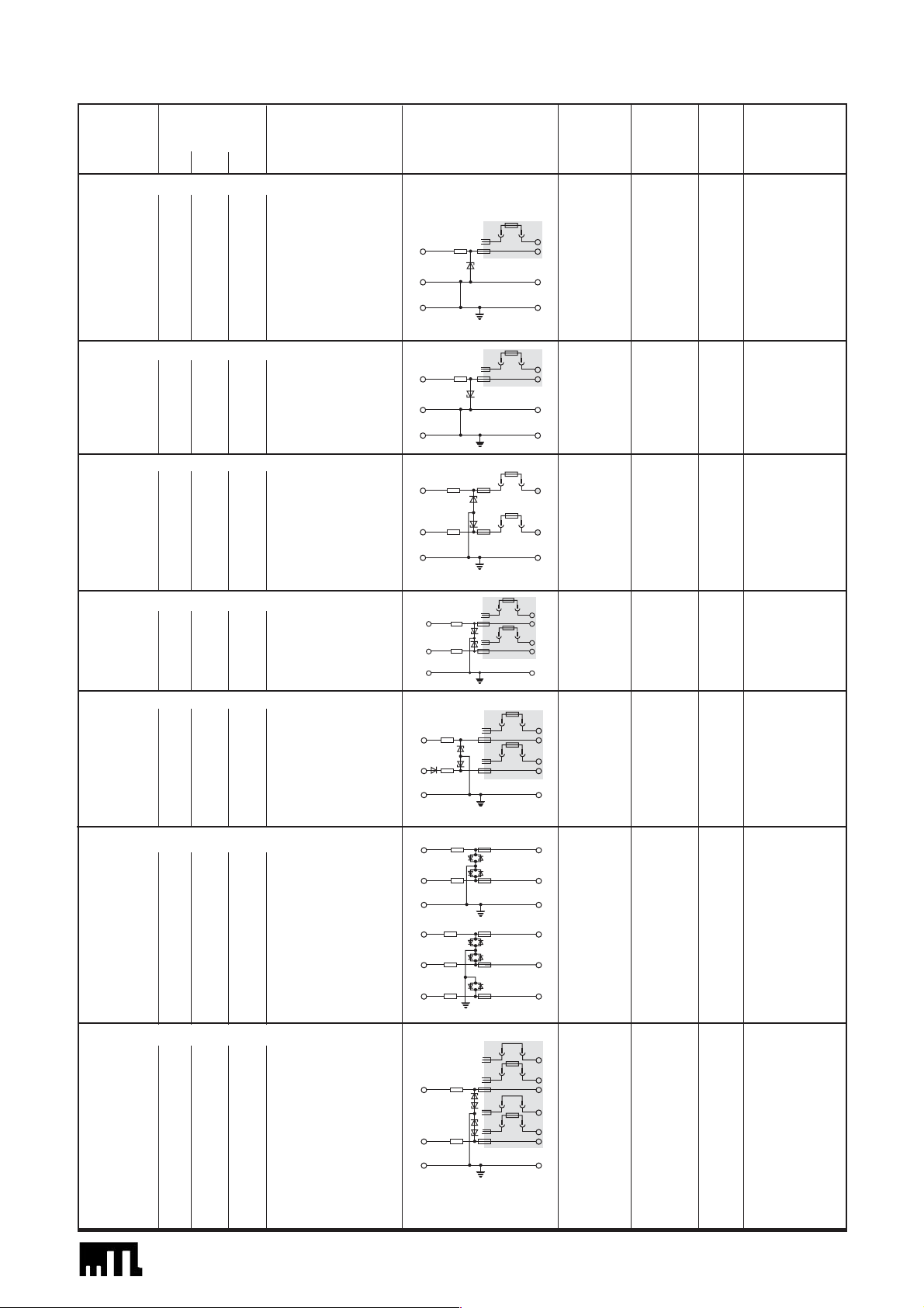
Model Safety Application Basic circuit Max. end- Vwkg at Vmax Internal safety
No. description to-end 10µA fuse/fuseMTL resistance disconnect(FD)†
(V) (ΩΩ) (mA) (ΩΩ) (V) (V) (mA)
SINGLE CHANNEL +VE
7122+ 22 150 147 18V dc systems 189 19.0 21.7 50 (FD)
7028+ 28 300 93 332 26.0 27.0 50
7128+ 28 300 93 Controller outputs, 342 26.0 27.2 50 (FD)
solenoids
7128P+ 28 234 120 275 26.0 27.1 50 (FD)
7129P+ 28 164 171 Controller outputs, 211 25.0 26.5 50 (FD)
solenoids (IIB)
SINGLE CHANNEL –VE
7028– 28 300 93 For negative/ 332 26.0 27.0 50
floating power
7128– 28 300 93 supplies 342 26.0 27.2 50 (FD)
DOUBLE CHANNEL +VE
7162+ 10 50 200 6V dc systems 87 8.0 9.1 50 (FD)
10 50 200 87 8.0 9.1 50 (FD)
7164+ 12 1k 12 Low-level/logic 1058 9.0 10.0 50 (FD)
12 1k 12 return signals 1058 9.0 10.0 50 (FD)
7167+ 15 100 150 12V dc systems 140 13.0 14.2 50 (FD)
15 100 150 140 13.0 14.2 50 (FD)
DOUBLE CHANNEL (NON-SYMMETRICAL) –VE
7096– 26 300 87 332 23.5 24.4 50
20 390 52 424 18.5 19.2 50
7196– 26 300 87 342 23.5 24.6 50 (FD)
20 390 52 434 18.5 19.3 50 (FD)
RETURN-DIODE TYPE
7087+ 28 300 93 332 26.0 26.8 50
28 diode – 33 + 0.9V 26.0 26.8 50
7187+ 28 300 93 342 26.0 26.9 50 (FD)
28 diode – 43 + 0.9V 26.0 26.9 50 (FD)
7087P+ 28 234 120 261 26.0 26.8 80
28 diode – 30 + 0.9V 26.0 26.8 80
7187P+ 28 234 120 274 26.0 26.9 50 (FD)
28 diode – 43 + 0.9V 26.0 26.9 50 (FD)
SIMPLE AC, LOW LEVEL
7055ac 3 10 300 2- or 3-wire (floating) 241 0.6 at 1µA 3.0 1 0 0
3 10 300 RTDs 241 0.6 at 1µA 3.0 1 0 0
7056ac 3 10 300 3-wire (grounded) 24 0.3 at 1µA 2.3 100
3 10 300 RTDs 24
1
0.3 at 1µA 2.3 100
3 10 300 24
1
0.3 at 1µA 2.3 100
SIMPLE AC, HIGHER VOLTAGE
7261ac 9 90 100 Strain-gauge bridges 115 7.2 8.3 80
9 90 100 4-wire RTD's 115 7.2 8.3 80
7061Pac 9 350 26 384 7.2 8.5 50
9 350 26 Strain-gauge 384 7.2 8.5 50
7161Pac 9 350 26 bridge, sense, output 393 7.2 8.8 50 (FD)
9 350 26 393 7.2 8.8 50 (FD)
7264ac 12 1k 12 Strain-gauge 1048 10.0 11.1 50
12 1k 12 bridge sense 1048 10.0 11.1 50
7066Pac 12 75 160 97.2 9.8 10.9 80
12 75 160 Strain-gauge 97.2 9.8 10.9 80
7166Pac 12 75 160 bridge supply 110.1 9.8 11.2 50 (FD)
12 75 160 110.1 9.8 11.2 50 (FD)
Page 3

EUROPE (EMEA) Tel: +44 (0)1582 723633 Fax: +44 (0)1582 422283
AMERICAS Tel: +1 603 926 0090 Fax: +1 603 926 1899
ASIA PACIFIC Tel: +65 487 7887 Fax: +65 487 7997
E-mail: enquiry@mtl-inst.com Web site: www.mtl-inst.com
June 2004
CERTIFICATION
MTL7000 Series barriers protect devices located in all normally
occurring explosive atmospheres, including air/flammable gasmixtures, dusts and fibres. MTL7000 Series barriers are certified [EEx
ia] IIC (except MTL7129P+, certified IIB) BY BASEEFA to CENELEC
standards, by FM in the USA, CSA in Canada and also by other
authorities, providing worldwide certification. MTL7000 Series
barriers are designed to the same safety descriptions as MTL700
Series equivalents (in some cases slightly stricter) and can therefore be
used for the same applications.
HOW THEY WORK
All MTL7000 Series barriers are based on the same simple principle.
Each channel contains three stages of Zener or forward-connected
diodes and an ‘infallible’ terminating resistor. In the event of an
electrical fault in the safe area, the diodes limit the voltage that can
reach the hazardous area and the resistor limits the current: active
output-current limiting circuits are not used. An internal fuse protects
the diodes, and the three stages of voltage limitation ensure continued
safety if the first or second stage should fail. MTL7100 barriers have
an additional replaceable fuse which protects the internal fuse.
The MTL7000 Series includes seven key barrier types which cover the
majority of applications, simplifying barrier selection and the
maintenance of spares stocks.
SUB-SERIES
MTL7000 Series barrier circuits are based on the well-proven designs
originally developed for the MTL700 Series. To simplify identification
for those familiar with the latter, part numbers are the same for
equivalent barriers, but with a ‘0’, ‘1’ or ‘2’ inserted after the initial
‘7’ to identify the relevant sub-series:
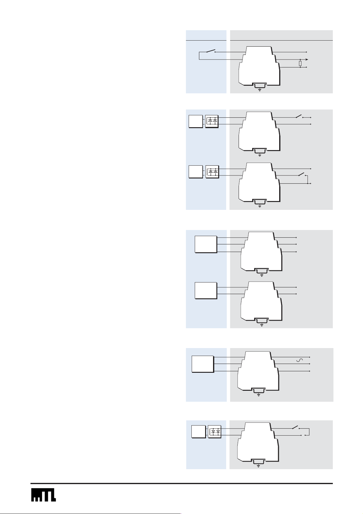
KEY BARRIERS SUMMARISED
TYPE APPLICATION KEY BARRIER
Analogue Resistance temperature detectors 7055ac 7060ac
input (low level) Thermocouples, ac sensors 7160ac
Analogue Controller outputs, one line earthed 7028+ 7128+
output Controller outputs, neither line earthed 7087+ 7187+
dc power supply
26.0V 20-35V
Analogue Transmitters, 2-wire, 4/20mA 7087+ 7206
input (high level) 7187+
Digital (on/off) Switches 7087+ 7207+
input 7187+
Digital (on/off) Solenoids, alarms, LEDs 7028+ 7208+
output 7128+
Note: the circuit shown is as an example only.
Standard, fuse- or link-disconnect options are shown shaded in the
'basic circuits' in the specifications tables.
MTL7000 standard
MTL7100 fuse-disconnect
MTL7200 link-disconnect
}
}
2
2
3
4
5
6
1
1
1
1
2
3
4
5
6
†All barriers have internal, inaccessible, safety fuses. MTL7100 barriers have additional
replaceable fuses, lower in value than the internal fuses. It is the value of the replaceable fuse
that is quoted for MTL7100 barriers.
Note 1: 24
Ω
±0.15Ωat 20°C, channels track within 0.15Ωfrom –20 to +60°C.
Note 2: In star-connected barriers (eg, MTL7060/7160), the two channels are interlocked
such that the voltage between them cannot exceed the working voltage, V
wkg
.
Note 3: MTL7278ac: the working voltage between the two interlocked channels is 24.0V;
V
max
is 25.3V.
Note 4: Limited availability. Use MTL7706+ as an alternative.
‘P’ suffix – Barriers with a ‘P’ suffix are higher-power versions of the standard devices
with lower end-to-end resistance, except the MTL7061Pac/7161Pac. They are suitable for
type IIC gas groups, except MTL7129P+ which is designed for IIB.
WARNING – Check compatibility of the electrical safety
parameters of the field equipment with those of the barriers to
make sure that the combination is safe.
Model Safety Application Basic circuit Max. end- Vwkg at Vmax Internal safety
No. description to-end 10µA fuse†/fuseMTL resistance disconnect (FD)
(V) (ΩΩ) (mA) (ΩΩ) (V) (V) (mA)
STAR-CONNECTED AC
2
7060ac 9 75 120 Active dc and 101 7.2 8.5 50
9 75 120 ac sensors, 101 7.2 8.5 50
7160ac 9 75 120 thermocouples 110.1 7.2 8.8 50 (FD)
9 75 120 110.1 7.2 8.8 50 (FD)
7265ac 15 100 150 131 12.0 13.0 50
15 100 150 2-wire dc/ac 131 12.0 13.0 50
7278ac
3
28 600 47 systems 640 +24.0 +25.9 50
–22.3 –23.8
28 600 47 640 +24.0 +25.9 50
–22.3 –23.8
ACTIVE BARRIERS
7106
4
28 300 93 Transmitters – – 35 50
7206
4
28 300 93 Transmitters – – 35 50
7207+ 28 300 93 Switches 348 + 1.2V – 35 50
28 diode 31 + 0.9V – – 50
7208+ 28 300 93 Solenoids, alarms, 348 + 1.2V – 35 50
LEDs
DUMMY BARRIERS
7099 – – – Securing and earthing – – – –
unused cables and screens.
7299 – – – Feed-through connections – – – –
for power comb.
SPECIFICATIONS (continued)
Page 4

EUROPE (EMEA) Tel: +44 (0)1582 723633 Fax: +44 (0)1582 422283
AMERICAS Tel: +1 603 926 0090 Fax: +1 603 926 1899
ASIA PACIFIC Tel: +65 487 7887 Fax: +65 487 7997
E-mail: enquiry@mtl-inst.com Web site: www.mtl-inst.com
June 2004
The MTL7106/MTL7206 is a single-channel barrier designed
primarily for energising a conventional or 'smart' 2-wire 4/20mA
hazardous-area transmitter. They can be thought of as an MTL7128–
or an MTL7028– barrier with a built-in floating power supply and
electronic over-volt protection. It provides a high voltage output (which
is negative with respect to earth) to power the transmitter and delivers
a 4/20mA signal into an earthed load in the safe-area. The novel
design is noted for its extreme accuracy.
Supply voltage
20 to 35V dc
Supply current
40mA typical at 20mA with 28V dc supply
45mA typical at 20mA with 24V dc supply
60mA maximum at 20mA with 20V dc supply
Voltage for transmitter and lines
16.0V minimum at 20mA with 250Ω load
11.25V minimum at 20mA with 500Ω load
Note that the output voltage is negative with respect to earth.
Safe-area load resistance
0 to 500Ω
Output current
0 to 23.6mA
Accuracy
±2µA (4 to 20mA)
Out of range capability
Over-range; >20mA to 23.6mA
Under-range; <4mA to 0mA
ACTIVE BARRIERS
MTL7106/7206
for 2-wire 4/20mA and ‘smart’
transmitters
HART®is a registered trademark of HART Communication Foundation
SPECIFICATION
MTL7106/MTL7206, MTL7207+ and 7208+ active barriers
The MTL7106/MTL7206, MTL7207+ and 7208+ barriers have
built-in overvolt protection, allowing their use with unregulated power
supplies. In many applications, eg, sensor inputs or controller outputs,
there is insufficient power available to blow the barrier fuse and this
additional protection is not necessary. But, where the barrier is
connected to a power supply, eg, for energising transmitters, switches,
solenoids or local alarms, overvolt protection allows the barriers to be
used with unregulated supplies up to 35V dc and also gives protection
against faulty wiring during commissioning. The MTL7206, 7207+,
7208+ are equipped with a loop disconnect at power supply terminal
1 while the MTL7106 has a fuse-disconnect.
Nearest equivalent passive barriers
MTL7106 nearest equivalent MTL7128–/7187+
MTL7206 nearest equivalent MTL7028–/7087+
MTL7207+ nearest equivalent MTL7087+/7187+
MTL7208+ nearest equivalent MTL7028+/7128+
‘Smart’ compatibility
HART Communication Foundation HART
®
Honeywell DE
Yokogawa BRAIN
Foxboro ‘smart’
Fuji ‘smart’
Chessel 3500 Series
Patent Nos
UK: 2205699
European (Germany, France, Italy): EP 0 294 139 BI
USA: 4967302
4
5
6
1
2
3
4/20mA
0V
+20 to 35V
4/20mA
+
–
Load
resistor
250mA
MTL7206
Loop disconnect link
MTL7106
Fuse
disconnect
100mA
Hazardous
area
Safe area
Page 5

EUROPE (EMEA) Tel: +44 (0)1582 723633 Fax: +44 (0)1582 422283
AMERICAS Tel: +1 603 926 0090 Fax: +1 603 926 1899
ASIA PACIFIC Tel: +65 487 7887 Fax: +65 487 7997
E-mail: enquiry@mtl-inst.com Web site: www.mtl-inst.com
June 2004
SPECIFICATION
Supply voltage, terminal 1
+10 to +35V dc
Normal operation
In normal operation the protection circuit introduces only a small
voltage drop and shunts less than 1.5mA to earth, so its overall
effect is minimal
Supply voltage >27V
If the supply voltage exceeds about 27V, causing the Zener
diodes to conduct, or if the safe-area load has a very low
resistance, the supply current is limited automatically to <50mA.
This protects the fuse and power supply and enables the loop to
continue working.
Supply current
At Vs <26V; Iout + 1.5mA max
At Vs >28V or low load resistance; limited to <50mA
Internal fuse, terminal 1
50mA
Reverse voltage protection, terminal 1
Yes
Maximum voltage drop, terminals 1 to 4
[(Iout x 350Ω) + 1.2]V (current not limited)
Output current (Iout), terminal 4
Up to 35mA
Leakage to earth
1.5mA max
MTL7208+
for digital (switched) outputs
MTL7207+
for digital (switch) inputs
Maximum voltage drop, terminals 1 to 4
[(Iout x 348Ω) + 1.2]V (current not limited)
Output current (Iout), terminal 4
Up to 35mA
Leakage to earth
1.5mA max
Internal fuse, terminal 2
50mA
Maximum voltage drop, terminals 5 to 2
[(I
out
x 33Ω) + 0.9]V
4
5
6
1
2
3
50mA
Current limit
1.5mA max
I
out
+
0V
10 to 35V dc max
50mA
Loop disconnect link
Hazardous
area
Safe area
Hazardous
area
Safe area
4
5
6
1
2
3
50mA
Current limit
1.5mA max
I
out
+
10 to 35V dc max
LED,
alarm,
solenoid,
etc
Loop disconnect link
0V
Page 6

EUROPE (EMEA) Tel: +44 (0)1582 723633 Fax: +44 (0)1582 422283
AMERICAS Tel: +1 603 926 0090 Fax: +1 603 926 1899
ASIA PACIFIC Tel: +65 487 7887 Fax: +65 487 7997
E-mail: enquiry@mtl-inst.com Web site: www.mtl-inst.com
June 2004
SPECIFICATION
Input voltage range (terminals 2 and 3)
20 to 26.8V
Maximum input voltage capability
35V
Power source requirement
Power source must be capable of delivering at least 1.8A
Trip mechanism
Minimum trip operating voltage: 26.8V (at 20°C ambient) at
output terminal 1 wrt earth
Temperature coefficient: +18.4mV/°C
MTL7991
power feed module
GENERAL SPECIFICATION
Ambient temperature limits
–20 to +60°C (FM/CSA) continuous working
–20 to +40°C (BASEEFA) continuous working
–40 to +80°C storage
Humidity limits
5 to 95% RH
Case flammability
UL94: V-2
Terminations
Terminals accommodate conductors up to 2.5mm
2
Hazardous-area terminals are identified as dark blue
Colour coding of barrier type (label on top surface)
Red: Positive polarity (+)
Black: Negative polarity (–)
Black (with red text): MTL7106/7206
Grey: Non-polarised (ac)
White: MTL7099/7299 dummy barrier
Orange: MTL7991 power feed module
Weight
100g approximately
Mounting and earthing
Clamping onto standard 35mm 'top-hat' DIN-rail: 7.5mm (low
profile) or 15mm (high profile)
Note: All specifications quoted at 20°C ambient unless otherwise stated.
The MTL7991 power feed module incorporates both voltage and
current sense mechanisms to protect barrier circuits by activating a
solid-state trip mechanism when fault or overload conditions occur in
the power source circuit. Resetting the module after tripping is done
by interrupting the supply to the unit. A red LED indicates a circuit trip
condition and a green LED the availability of power at the outputs.
DIMENSIONS (mm)
Output current range (terminal 1 wrt earth)
0 to 800mA
LED indication
Green: indicates power at output terminals
(ie, power being fed to barriers)
Red: indicates trip condition
(ie, overvoltage or overcurrent state)
Maximum voltage drop
20mV at 0mA load, –20 to +60°C
1.0V at 800mA load, –20 to +60°C
Maximum number of barriers powered
Load dependent, eg:–
40 x MTL7087+* at 20mA (4/20mA loops)
* Or fuse-disconnect or ‘P’ versions
Safe area
4
5
63
2
1
102.1 (7.5mm rail)
109.6 (15mm rail)
101.3
99
Hazardousarea
terminals
Safe-area
terminals
Installation and approval side label
MTL7XXX
Fuse/link positions (MTL7100/7200)
Channel 2
(terminal 2 to 5)
Channel 1
(terminal 1 to 4)
7
MTL7XXX
Colour-coded top label
+0.3
–0.0
To barriers via
4
5
Green
power
6
LED
MTL7991
Solid-state
Voltage
sense
switch
Trip
circuit
Current
sense
800mA max
1
2
Red
3
fault
LED
power comb
External power
supply
20 to 26.8V dc
at 1.8A min
Page 7

EUROPE (EMEA) Tel: +44 (0)1582 723633 Fax: +44 (0)1582 422283
AMERICAS Tel: +1 603 926 0090 Fax: +1 603 926 1899
ASIA PACIFIC Tel: +65 487 7887 Fax: +65 487 7997
E-mail: enquiry@mtl-inst.com Web site: www.mtl-inst.com
June 2004
Vibration probes
The 3-wire transmitters used with vibration monitoring equipment are
invariably supplied by a –24V dc power supply – hence the
recommended barrier choice is the negatively-polarised MTL7096–
/7196–. The ‘third terminal’ makes this choice ideal for these 3-wire
applications.
2-wire transmitters, 4/20mA, conventional and smart
Recommended barriers for use with 'conventional' and 'smart'
4/20mA transmitters (fed by a regulated supply) are the MTL7087+
/7187+ or MTL7087P+/7187P+. These provide up to 14.2V at V
wkg
and 20mA for a transmitter and its lines as well as 5V for the typical
250Ω load. This application and these barriers are suitable for use
with the optional power comb.
The MTL7106/7206 is recommended for applications where an
unregulated supply of up to 35V is used. It provides 16.0V for
transmitter and lines at 20mA as well as 5V for a typical 250Ω load.
With the MTL7106/7206 terminal 4 is negative with respect to earth,
so the connections to terminals 4 and 5 should be reversed.
MTL7000 SERIES BARRIER
APPLICATIONS
MTL7000 Series barriers protect devices located in all normally
occurring explosive atmospheres, including air/flammable gas
mixtures, dusts and fibres. Applications covered include the protection
of installations incorporating uncertified devices (‘simple apparatus’)
such as thermocouples, switches and resistive sensors, or separately
certified ‘energy storing’ (or ‘voltage producing’) apparatus including
ac sensors, transmitters and current-to-pneumatic (I/P) converters.
Recommended choices for specific applications are discussed briefly
in the following pages.
These are examples, and many other configurations will suggest
themselves. For advice on a particular application, please contact MTL.
ANALOGUE INPUTS (HIGH-LEVEL)
Hazardous
area
Safe area
Slidewire displacement transducers
The simplest choice is the MTL7060ac/7160ac. This barrier supplies
power and brings back a unipolar signal.
ac sensors, photocells, microphones and turbine flowmeters
The MTL7060ac/7160ac is the recommended choice for these
devices. While many of these are designated ‘simple apparatus’ and
thus do not need certification, note that some ac sensors may be
subject to a significant level of inductance and will therefore need to
be designed and certified for hazardous-area locations.
Thermocouples and mV sources
The recommended barrier for thermocouples and mV sources is the
MTL7060ac/7160ac. This 2-channel non-polarised barrier retains the
‘earth-free’ nature of the signal and, providing the receiver’s input
‘floats’, rejects common-mode ac and dc interference up to at least 7V
and is unaffected by earth faults on the primary element.
ANALOGUE INPUTS (LOW-LEVEL)
4
5
6
MTL7087+
MTL7187+
MTL7087P+
MTL7187P+
MTL7106
MTL7206
1
2
4/20mA
3
+26V
1–5V
250Ω
0V
Transducer
Photocell
Microphone
Turbine
flowmeter
Probe
driver
4
5
6
MTL7096–
MTL7196–
Compensating cable
4
5
6
MTL7060ac
MTL7160ac
4
5
6
MTL7060ac
MTL7160ac
1
2
1
2
1
2
Monitor
–24V
3
3
3
V out
0V
Recorder
Controller
Data logger
Computer
Earth
free
signal
4
5
6
MTL7060ac
MTL7160ac
1
2
3
+7.2V
V out
0V
Page 8

EUROPE (EMEA) Tel: +44 (0)1582 723633 Fax: +44 (0)1582 422283
AMERICAS Tel: +1 603 926 0090 Fax: +1 603 926 1899
ASIA PACIFIC Tel: +65 487 7887 Fax: +65 487 7997
E-mail: enquiry@mtl-inst.com Web site: www.mtl-inst.com
June 2004
RTDs
For 3-wire RTDs, a single MTL7055ac barrier is the most economical
choice. This is suitable for use with a floating bridge – the two leads
from the bridge arms are protected by the barrier with the third
(supply) lead being earthed through the barrier. The barrier has a low
end-to-end resistance of only 24Ω/channel to minimise span changes
and its channels track within 0.15Ω (between –20 to +60°C) to
minimise zero shift with temperature.
If the bridge circuit is already earthed, the third barrier channel
provided by an MTL7056ac is needed. For extreme accuracy, 3
channels and an earth-free bridge can be used, a configuration that
cancels out the small errors due to barrier leakage.
4-wire constant-current circuits do not need matched barrier
resistances and can be protected by two MTL7261ac barriers. If the
increase in loop resistance is too great, use two MTL7055ac barriers
instead.
Channels 2 and 3 (those between terminals 5 & 2, and 6 & 3
respectively) track to within 0.15Ω between –20 and 60°C.
Hazardous
area
Safe area
4
5
6
1
2
3
Receiver
MTL7055ac
4
5
6
1
2
3
Receiver
MTL7056ac
4
5
6
1
2
3
Receiver
4
5
6
1
2
3
MTL7055ac
MTL7055ac
MTL7261ac
MTL7261ac
Single strain-gauge bridges
This shows an arrangement using two or three barriers, which is safe
in IIC gases. With the MTL7261ac, the circuit is powered from a 14V,
230Ω source; if the bridge resistance is 230Ω, then the bridge
voltage is 7V . If the bridge resistance is 350Ω, then the bridge voltage
is 8.4V.
An MTL7264ac can be used to sense the bridge supply voltage.
An MTL7261ac is used here for the mV output.
An MTL7166Pac provides 12.3V for a 350Ω bridge with a 20V
supply. MTL7161Pac's can be used for the sense and pick-off circuits.
STRAIN-GAUGE BRIDGES
4
5
6
4
5
6
4
5
6
MTL7261ac
MTL7264ac
MTL7261ac
1
2
3
1
2
3
1
2
3
+7V
–7V
0V
+
Sense
–
Output (mV)
Page 9

EUROPE (EMEA) Tel: +44 (0)1582 723633 Fax: +44 (0)1582 422283
AMERICAS Tel: +1 603 926 0090 Fax: +1 603 926 1899
ASIA PACIFIC Tel: +65 487 7887 Fax: +65 487 7997
E-mail: enquiry@mtl-inst.com Web site: www.mtl-inst.com
June 2004
ANALOGUE OUTPUTS
Double strain-gauge bridges
Quite frequently there is a demand to monitor two load cells, and a
possible circuit, safe in IIC, is shown.
Here, the lower voltage drop of the MTL7066Pac is an advantage.
The MTL7066Pac supplies power to the bridge(s) whilst two
MTL7061Pac/7161Pac barriers interface with the sense and pick-off
circuits.
Using 350Ω bridge systems, the following voltages are available from
an MTL7066Pac with a ±10V supply:
1 bridge: 12.8V
2 bridges: 9.4V
Hazardous
area
Safe area
Controller outputs (I/P converters)
The single-channel MTL7028+/7128+ with a voltage drop of
6.7V/6.9V is the recommended choice for most controller outputs.
Higher-power versions are available: the MTL7128P+ (5.5V drop) is
suitable for IIC applications; the MTL7129P+ (4.22V drop) for IIB
applications.
For controllers with an output circuit separated from the 0V rail by the
control transistor, the 2-channel MTL7087+/7187+ is the preferred
choice as the return channel can handle up to 26.0V/26.0V allowing
the control signal to be turned off completely. The voltage drop is
8.2V/8.6V at 20mA. A higher-power version of the latter, the
MTL7087P+ /7187P+, is also available. The return channel of these
barriers handle up to 26.0V/26.0V and the maximum voltage drop
is only 6.72V/7.24V.
The MTL7087+/7187+ and MTL7087P+/7187P+ are also suitable
for controllers containing a resistor which enables the return current to
be monitored for high-integrity operation.
5
6
4
MTL7066Pac
1
2
3
+10V
–10V
0V
4
5
6
MTL7061Pac
MTL7161Pac
4
5
6
MTL7061Pac
MTL7161Pac
P
I
4
5
MTL7028+
6
MTL7128+
MTL7128P+
*MTL7129P+
1
2
3
1
2
3
1
2
3
+
Sense
–
Output (mV)
+26V
0V
* CENELEC gas group IIB
(C & D N. America)
P
I
4
5
6
MTL7087+
MTL7187+
MTL7087P+
MTL7187P+
1
2
3
+26V
0V
+26V
P
I
4
5
6
MTL7087+
MTL7187+
MTL7087P+
MTL7187P+
1
2
3
Monitor
0V rail
Page 10
EUROPE (EMEA) Tel: +44 (0)1582 723633 Fax: +44 (0)1582 422283
AMERICAS Tel: +1 603 926 0090 Fax: +1 603 926 1899
ASIA PACIFIC Tel: +65 487 7887 Fax: +65 487 7997
E-mail: enquiry@mtl-inst.com Web site: www.mtl-inst.com
June 2004
Alarms, LEDs, solenoids valves, etc
For these applications, the MTL7028+/7128+ is recommended.
Higher-powered versions are available: the MTL7128P+ is suitable for
IIC applications; the MTL7129P+ for IIB applications.
The MTL7208+ is recommended for applications where an
unregulated supply of up to 35V is used.
If the control switch is to earth, then the 2-channel MTL7087+ /7187+
barrier should be used, or, alternatively, the MTL7087P+/7187P+
higher-power version. If the supply is poorly regulated use the
MTL7207+.
DIGITAL (ON/OFF) OUTPUTS
Switches
The normal choice is the MTL7087+/7187+ with a regulated supply.
The MTL7207+ is recommended for applications where an
unregulated supply of up to 35V is used.
For optimum power transfer, with relays the resistance of the load
should be approximately equal to the combined resistance of the two
channels and the relay coil should then be rated at about half the
supply voltage.
DIGITAL (ON/OFF) INPUTS
+26V
*CENELEC gas group IIB
(C & D N. America)
6
4
5
1
2
3
LED,
alarm
+26V
0V
0V
6
4
5
1
2
3
MTL7028+
MTL7128+
MTL7128P+
*MTL7129P+
MTL7208+
MTL7087+
MTL7187+
MTL7087P+
MTL7187P+
MTL7207+
LED,
alarm
Low-level to 12V dc systems
The two channels of the MTL7162+, MTL7164+ and MTL7167+ can
be combined safely in IIC.
The MTL7164+ can be used for low-level logic return signals. The
MTL7162+ and MTL7167+ are used for 6V dc and 12V dc systems
respectively.
+VE DC SYSTEMS
18V dc systems
The single-channel MTL7122+ is recommended for 18V dc systems.
6
4
5
1
2
3
MTL7122+
dc
systems
0V
+18V
6
4
5
1
2
3
MTL7162+
MTL7164+
MTL7167+
dc
systems
0V
+6V/9V/12V
+6V/9V/12V
NEGATIVE AND FLOATING POWER SUPPLIES
Digital (on/off) outputs
The MTL7028–/7128– is used with a negative power supply and
positive earth. Typically used for digital inputs or outputs, as shown.
The MTL7028-/7128- can also be used with floating power supplies,
for transmitters.
AC AND DC SYSTEMS
High-level ac and dc systems
The versatile star-connected MTL7265ac and MTL7278ac allow
V
wkg
to be developed from each channel to ground but only allow
V
wkg
to be developed between channels. This provides some
common-mode voltage capability and can allow higher cable
parameters to be used.
6
4
5
1
2
3
MTL7265ac
MTL7278ac
dc and ac
systems
0V
12V/24V
Hazardous
area
Safe area
4
5
6
MTL7087+
MTL7187+
MTL7207+
1
2
3
+26V
Logic signal
0V
LED,
alarm
5
6
4
MTL7028–
MTL7128–
1
2
3
+ –
26V
Page 11

EUROPE (EMEA) Tel: +44 (0)1582 723633 Fax: +44 (0)1582 422283
AMERICAS Tel: +1 603 926 0090 Fax: +1 603 926 1899
ASIA PACIFIC Tel: +65 487 7887 Fax: +65 487 7997
E-mail: enquiry@mtl-inst.com Web site: www.mtl-inst.com
June 2004
POWER COMB APPLICATIONS
The PWC7000 power comb is invaluable for saving installation time
and wiring when connecting a 24V dc power source to a number of
barriers.
Typical applications include hazardous-area switches, 4/20mA
transmitters and solenoids. The diagram illustrates the configuration
for 3 barriers but up to 40 barriers can be served by this method.
The MTL7991 power feed module would normally be used with
standard barriers such as MTL7087+ and MTL7087P+ because the
current/voltage trip protection mechanism of the MTL7991 removes
the need for replaceable fuses in the barriers.
The MTL7099/7299 dummy barriers can be used instead of the
MTL7991 for direct ‘feed-through’ connection of a 24V dc supply. In
these circumstances, replaceable fuse barriers such as MTL7187+
and MTL7187P+ may be preferred.
The MTL7299 dummy barrier has a removable link between
terminals 1 and 2 for easy disconnection of the supply.
Other units which can use the power comb: MTL7106
MTL7206
MTL7207+
MTL7208+
SPARE CABLE CORES AND SCREENS
The MTL7099/7299 dummy barriers are used primarily for securing
and earthing unused cables and screen connections. Hazardous area
terminals 4, 5 and 6 (and safe area terminal 3) are internally
connected to the DIN-rail mounting/earth connection.
Hazardous
area
Safe area
WIRED IN APPLICATIONS
MTL7299s can be 'looped-in' to provide link-disconnects for MTL70xx
barriers, eg. as shown here with an MTL7055ac and an RTD.
For high accuracy or sensitive low level applications check that the
additional connections do not degrade the signals.
4
5
MTL7087+
6
MTL7187+
MTL7087P+
MTL7187P+
MTL7991
OR
MTL7099
MTL7299
1
2
3
1
2
3
External 24V dc
supply
0V
Logic
signal
0V
Unused
cable
cores
and
screens
4
5
6
MTL7087P+
MTL7187P+
4
5
MTL7087+
6
MTL7187+
MTL7087P+
MTL7187P+
4
5
6
MTL7087+
MTL7187+
MTL7099
MTL7299
1
2
3
1
2
3
1
2
3
Logic
signal
0V
Logic
signal
0V
Power comb
PWC7000
4
5
6
4
5
6
4
5
6
1
2
3
MTL7055ac
1
2
3
MTL7299
Receiver
1
2
3
MTL7299
Page 12

EUROPE (EMEA) Tel: +44 (0)1582 723633 Fax: +44 (0)1582 422283
AMERICAS Tel: +1 603 926 0090 Fax: +1 603 926 1899
ASIA PACIFIC Tel: +65 487 7887 Fax: +65 487 7997
E-mail: enquiry@mtl-inst.com Web site: www.mtl-inst.com
June 2004
MAXIMUM CABLE PARAMETERS
Model no. Number of single Maximum permissible cable parameters
2
channels inter-
connected Earth
1
BASEEFA (group IIC (hydrogen)) FM (Groups A & B) Matched
3
within return Capacitance Inductance L/R ratio Capacitance Inductance power
hazardous area used? (µF) (mH) (µH/ΩΩ) (µF) (mH) (W)
MTL7106/7206 1 Yes 0.083 4.1 54 0.14 4.27 0.65
MTL7207+ 2 Yes 0.083 4.1 54 0.12 4.0 0.65
MTL7208+ 1 Yes 0.083 4.1 54 0.12 4.0 0.65
MTL7122+ 1 Yes 0.165 1.66 44 0.2 1.4 0.81
MTL7028+/7128+ 1 Yes 0.083 4.1 54 0.12 4.0 0.65
MTL7128P+ 1 Yes 0.042 1.26 42 0.16 2.86 0.83
MTL7028–/7128– 1 Yes 0.083 4.1 54 0.13 4.0 0.65
MTL7129P+ 1 Yes – – – 0.49 6.25 1.19 IIB (C&D) only
MTL7055ac 1 Yes 1000 0.4 158 1000 0.4 0.23
2 Yes 1000 0.1 79 150 0.1 0.45
2 No 40 0.4 79 150 0.1 0.45
3 No 40 0.22 59 – – 0.68
4 Yes 40 0.035 31.25 – – 0.92
MTL7056ac 1 Yes 1000 0.4 158 – – 0.23
3 No 40 0.22 59 – – 0.68
MTL7060ac/7160ac 1 Yes 4.9 2.47 131 4.50 2.50 0.27
2 Yes 4.9 0.61 65 – – 0.54
MTL7061Pac/7161Pac 2 No 0.309 54.2 307 0.42 13.0 0.12
MTL7261ac 1 Yes 4.9 3.55 158 3.1 3.5 0.23
2 Yes 4.9 0.88 79 0.4 1.0 0.45
MTL7162+ 1 Yes 3.0 0.89 71 3.0 1.0 0.50
2 Yes 3.0 0.22 35 – – 1.0
2 No 1.97 2.93 117 –- –
MTL7164+ 1 Yes 1.41 246 987 1.5 200 0.04
2 Yes 1.41 61.7 493 1.0 60 0.08
MTL7264ac 1 Yes 1.41 246 987 1.5 200 0.04
2 Yes 1.41 61.7 493 0.18 60 0.08
No 0.125 246 493 0.18 60 0.08
MTL7265ac 1 Yes 0.58 1.58 63 0.7 1.3 0.56
2 Yes 0.58 0.4 31 0.7 1.4 1.13
MTL7066Pac/7166Pac 2 Yes 1.41 0.36 37 1.80 1.27 0.96
MTL7167+ 1 Yes 0.58 1.58 63 0.7 1.7 0.56
2 Yes 0.58 0.4 31 0.5 0.4 1.13
MTL7278ac 1 Yes 0.083 16.1 108 0.12 14 0.33
2 Yes 0.083 4.02 54 0.12 4.2 0.66
MTL7087+/7187+ 2 Yes 0.083 4.1 54 0.13 4.2 0.65
MTL7087P+/7187P+ 2 Yes 0.042 1.26 42 0.13 2.47 0.84
MTL7096–/7196– 2 Yes 0.134 1.86 44 0.14 1.71 0.83
Notes
Key barriers in bold
1
If values are not quoted for when on earth return is not used, then those for an earth return ('Yes' in the tables) are applicable
2
For most practical purposes, the values of the parameters for groups IIB and IIA are respectively 3 and 8 times the values for group IIC
3
The maximum power that can be drawn from the barrier or barrier combination under fault conditions; used for assessing the temperature classification of
‘simple' hazardous-area apparatus
TERMINOLOGY
Safety description
The description of a barrier, eg, ’10V 50ž 200mA’, refers to the
maximum voltage of the terminating Zener or forward diode when an
internal safety fuse is blowing, the minimum value of the terminating
resistor, and the corresponding maximum short-circuit current. It is an
indication of the fault energy that can be developed in the hazardous
area and not of the working voltage or end-to-end resistance.
Polarity
Barriers may be polarised positive (‘+’) or negative (‘–’) or nonpolarised (‘ac’). Polarised barriers accept and/or deliver safe-area
voltages of the specified polarity only. Non-polarised barriers support
voltages of either polarity applied at either end. The exception is the
MTL7206 which takes a positive supply but provides an output
voltage which is negative with respect to earth.
End-to-end resistance
The resistance between the two ends of a barrier channel at 20°C, ie,
of the resistor and the fuse(s). If diodes or transistors are present, the
voltage drop of these is also quoted.
Working voltage (Vwkg)
The greatest steady voltage, of appropriate polarity, that can be
applied between the safe-area terminal of a ‘basic’ barrier channel
and earth at 20°C for the specified leakage current, with the
hazardous-area terminal open circuit.
Maximum voltage (Vmax)
The greatest steady voltage, of appropriate polarity, that can be
applied continuously between the safe-area terminal of any barrier
channel and earth at 20°C without blowing the internal safety
fuse/external replaceable fuse (MTL7100). For ‘basic’ barriers it is
specified with the hazardous-area terminal open circuit; if current is
drawn in the hazardous area, the maximum voltage for these barriers
is reduced. The ‘ac’ channels of ‘basic’ barriers withstand voltages of
the opposite polarity also – see the circuit diagrams included under
‘Applications’.
Fuse ratings
The greatest current that can be passed continuously through the fuse
for 1000 hours at 35°C.
Maximum safe-area voltage (Um)
The maximum permissible safe-area voltage (Um) for MTL7000 Series
barriers is 250V ac/dc.
Page 13

MTL7000/7100/7200 barriers
Select by barrier number and polarity,
e.g. MTL7028+
Mounting accessories
THR2 Standard DIN-rail, 35 x 7.5mm
THR7000 T-section DIN-rail, specially-plated,
35 x 7.5mm, 1m length
ISP7000 Insulating spacer
Standard earthing/earth-rail accessories
ETL7000 Earth terminal, DIN-rail mounted
IMB57 Insulating mounting block
ERB57S Ear th-rail bracket, straight
ERB57O Earth-rail bracket, offset
ERL7 Earth rail, 1m length
ETM7 Earth terminal, pack of 50
Standard tagging accessories
TAG57 Tagging strip, 1m length
TGL57 Tagging strip labels, set of 10 x 0.5m
BRI7000 Barrier identifier
BIL7000 Barrier identification labels, sheet of 120
BIL7000L Barrier identification labels, A4 sheet
of 126
HOW TO ORDER
Literature
INM7000 Instruction manual, MTL7000 Series
INM57ENC Instruction manual, MTL5000/7000
Series Enclosures
CD700... Customer drawings
Replaceable fuses/removable links
RFA7050 Replaceable fuse assemblies, 50mA,
pack of 5
RFA7100 Replaceable fuse assemblies, 100mA,
pack of 5
RLA7000 Removable link, pack of 5
Enclosures
DX070 Enclosure, for MTL7000 x 9
DX170 Enclosure, for MTL7000 x 22
DX430 Enclosure, for MTL7000 x 58
Module No. Bussed MTL7000 MTL7000 MTL7000 MTL700 MTL700 MTL700 Typical
Power ? Equivalent Original ATEX equivalent Original ATEX Application
Certificate Certificate Certificate Certificate
Number(s) Number(s) Number(s) Number(s)
MTL7710+/- No Half of Ex95C2261 BAS99ATEX7285 MTL710+/- Ex832452 BAS01ATEX7202 4/6V
MTL7162+/- Systems
MTL7715+/- No N/A N/A N/A MTL715+/- Ex832452 BAS01ATEX7202 12V Systems
MTL7715P+/- No N/A N/A N/A MTL715P+ Ex92C2373 BAS01ATEX7202 12V Systems
MTL7722+/- No MTL7122+/- Ex95C2261 BAS99ATEX7285 MTL722+/- Ex832452 BAS01ATEX7202 General Purpose
MTL7728+/- No MTL7028+/- Ex95C2261 BAS99ATEX7285 MTL728+/- Ex832452 BAS01ATEX7202 Analogue / Digital
MTL7128+/MTL7728ac No N/A N/A N/A MTL728ac Ex832452 BAS01ATEX7202 General Purpose
MTL7728P+/- No MTL7128P+/- Ex95C2261 BAS99ATEX7285 MTL728P+ Ex92C2373 BAS01ATEX7202 Analogue / Digital
MTL7755ac No MTL7055ac Ex95C2261 BAS99ATEX7285 MTL755ac Ex832452 BAS01ATEX7202 RTD, Grounded
MTL7756ac No MTL7056ac Ex95C2261 BAS99ATEX7285 N/A N/A N/A RTD, Grounded
MTL7760ac No N/A N/A N/A MTL760ac Ex832452 BAS01ATEX7202 Active sensors,
Thermocouples
MTL7761ac No MTL7261ac Ex95C2261 BAS99ATEX7285 MTL761ac Ex832452 BAS01ATEX7202 Strain Gauges
MTL7761Pac No MTL7061Pac Ex95C2261 BAS99ATEX7285 MTL761Pac Ex92C2373 BAS01ATEX7202 Load cell
MTL7161Pac
MTL7764+/- No MTL7164+/- Ex95C2261 BAS99ATEX7285 MTL764+/- Ex832452 BAS01ATEX7202 High resistance
MTL7764ac No MTL7264ac Ex95C2261 BAS99ATEX7285 MTL764ac Ex832452 BAS01ATEX7202 Strain / Level
Gauges
MTL7765ac No N/A N/A N/A MTL765ac Ex832452 BAS01ATEX7202 General Purpose
MTL7766ac No N/A N/A N/A MTL766ac Ex832452 BAS01ATEX7202 Strain Gauges
MTL7766Pac No MTL7066Pac Ex95C2261 BAS99ATEX7285 MTL766Pac Ex92C2373 BAS01ATEX7202 Strain Gauges
MTL7166Pac
MTL7767+/- No MTL7167+/- Ex95C2261 BAS99ATEX7285 MTL767+/- Ex832452 BAS01ATEX7202 Dual MTL715
MTL7779+/- No N/A N/A N/A MTL779+/- Ex832452 BAS01ATEX7202 Dual MTL728
MTL7787+/- Yes MTL7087+/- Ex95C2261 BAS99ATEX7285 MTL787S+ Ex832452 BAS01ATEX7202 Analogue / Digital
MTL7187+/MTL7787P+/- Yes MTL7087P+ Ex95C2261 BAS99ATEX7285 MTL787SP+ Ex92C2373 BAS01ATEX7202 Analogue / Digital
MTL7187P+
MTL7788+/- Yes N/A N/A N/A MTL788+/- Ex832452 BAS01ATEX7202 Transmitters
MTL7788R+/- Yes N/A N/A N/A MTL788R+/- Ex832452 BAS01ATEX7202 1—5V systems
MTL7796+/- No MTL7096+ Ex95C2261 BAS99ATEX7285 MTL796+/- Ex832452 BAS01ATEX7202 Gas Metering
MTL7196-
CORRELATION BETWEEN MTL7700 — MTL7000 — MTL700 BARRIERS (IIC)
EUROPE (EMEA) Tel: +44 (0)1582 723633 Fax: +44 (0)1582 422283
AMERICAS Tel: +1 603 926 0090 Fax: +1 603 926 1899
ASIA PACIFIC Tel: +65 487 7887 Fax: +65 487 7997
E-mail: enquiry@mtl-inst.com Web site: www.mtl-inst.com
June 2004
 Loading...