

Page 1
MTL646
IS Panel Mounting Serial Text Display
Instruction Manual
INM646
Page 2

ii
Page 3

INM646-1
Contents July 2003
1. Description
2. Operation
2.1 MTL646/7 protocol
2.2 MTL643/4 protocol
3. Intrinsic Safety Certification
3.1 Apparatus certificate (ATEX)
3.2 System certificates
3.3 Zones, groups and T rating
3.4 Power supply
3.5 External switches
3.6 Switch outputs
3.7 Certification label information
4. System Design for Hazardous Area
4.1 Cable length
4.2 Two wire system
4.3 Three wire system
4.4 Four wire system
4.5 Switch outputs
5. Installation
5.1 Location
5.2 Installation procedure
5.3 EMC
6. Configuration
6.1 Default configuration
6.2 Accessing the configuration menus
6.3 Summary of configurable functions
6.4 Quick access menu
The MTL646 is CE marked to show compliance with the
European Explosive Atmospheres Directive 94/9/EC,
the European EMC Directive 89/336/EEC
and the European Low Voltage Directive 73/23/EEC
7. Programming
7.1 Summary of MTL646/7 protocol
7.2 Command format
7.3 Response format
7.4 Operational modes
7.5 Multidrop operation
7.6 Summary of commands
7.6.1 Screen handling & text
7.6.2 Attributes
7.6.3 System commands
7.6.4 Line graphics
7.6.5 Pixel graphics
7.7 Graphics download
7.7.1 <DL> command
7.7.2 <DG> command
7.8 Cyclic Redundancy Check
7.8.1 Procedure for generating
CRC.
8. Maintenance
8.1 Fault finding during commissioning
8.2 Fault finding after commissioning
8.3 Servicing
8.4 Routine maintenance
8.5 Guarantee
8.6 Customer comments
9. Accessories
9.1 Tag number
9.2 MTL646/647 Programming Guide.
10. Index
iii
Page 4

iv
Page 5
MTL646 INM646-1
IS PANEL MOUNTING SERIAL TEXT DISPLAY July 2003
1. DESCRIPTION
The MTL646 is an intrinsically safe instrument
that can display text and simple graphics in a
hazardous area. Incorporating six operator
switches, two solid state outputs and a backlit
graphical display, it forms a simple operator
interface for machine or process control
applications.
The MTL646 text display has been certified
intrinsically safe by European Notified Body
Intertek Testing Services (ITS) to the ATEX
Directive 94/9/EC.
Safety approvals from authorities outside
Europe are being obtained, please contact
MTL for the latest information.
Housed in a robust 144 x 72 panel mounting
DIN enclosure, the text display has an IP65
front panel and is supplied with a gasket to
seal the joint between the instrument and the
panel.
2. OPERATION
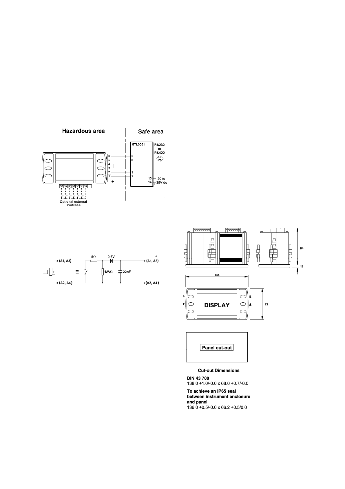
Fig 1 shows a simplified block diagram of a
MTL646 serial text display. The instrument is
connected to a serial data galvanic isolator in
the safe area via two, three or four wires that
carry both power and bi-directional
communication. The switch outputs may be
controlled and the operator switches
interrogated from the safe area via the serial
communication link.
The MTL646 serial text display has been
designed to operate with a certified galvanic
isolator that has an RS232 or RS422 safe area
port. This enables the MTL646 to be controlled
and interrogated by a process computer or a
dedicated instrument such as a PLC.
Installation and commissioning are simple. An
MTL646 serial text display may be operated on
a simple two-wire system that provides both
power and bi-directional communications. Two
MTL646 displays with separate addresses may
be multi-dropped from a two-wire system and
up to four displays from a three-wire system.
Up to 14 serial text displays may be address
from one RS232 or 422 port.
Section 7 of this manual includes a summary of
the MTL programming protocol and instruction
set. Detailed information is contained in the
Programming Guide, which may be
downloaded from the MTL web site
www.mtl-inst.com
Fig 1 Simplified block diagram of MTL646
2.1 MTL646/7 protocol
MTL646/7 protocol enables text to be written
anywhere on the screen in five different font
sizes, together with lines, boxes and
bargraphs. Simple bit map graphics may also
be downloaded to the display and all
characters can be reversed or flashed.
Information may also be written to a hidden
screen that may be displayed when required.
The protocol enables each of the six front
panel push-buttons to be interrogated so they
may be used for operator controls. By
displaying the switch function on the screen
adjacent to the button, ‘soft switches’ can be
created. If larger industrial size push-buttons
are required, these may be connected to the
MTL646 terminals. When external switches
are used the instrument front panel switches
are disabled.
Two single pole solid state outputs may be
used to switch certified hazardous area loads
such as sounders, beacons and valves.
2.2 Legacy protocol
The legacy protocol contained in the MTL646
allows the instrument to replace an MTL644 IS
text display. All the functions of an MTL644
are replicated, but with the advantage of a
backlit display and certification to the ATEX
Directive.
Legacy protocol only allows three external
switches S1, S2 & S3, not the front panel pushbuttons, to be used for operator inputs.
Similarly, the MTL644 only has one output
control, so the two switch outputs operate in
parallel.
When using the legacy protocol, the
configuration menus are only operational
between power being applied to the MTL646
and the first message being received.
1
Page 6

3. INTRINSIC SAFETY CERTIFICATION
3.1 Apparatus certificate (ATEX)
The MTL646 has been issued with EC-Type
Examination Certificate ITS03ATEX21172 by
Intertek Testing Services (ITS) confirming
compliance with the European ATEX Directive
94/9/EC for Group II, Category 1, gas
atmospheres, EEx ia IIC T5. The instrument
bears the Community Mark and, subject to
local codes of practice, may be installed in any
of the European Economic Area (EEA)
member countries, which currently comprise:
Austria, Belgium, Denmark, Finland, France,
Germany, Greece, Iceland, Ireland, Italy,
Liechtenstein, Luxembourg, The Netherlands,
Norway, Portugal, Spain, Sweden and the
United Kingdom. Certificates to the ATEX
Directive are also accepted in Switzerland and
the Czech Republic. This instruction manual
describes installations that conform with
PD60079-14:2000 Electrical Installation in
Hazardous Areas. When designing systems
for installation outside the UK, the local Code
of Practice should be consulted.
3.2 System certificates
In addition to the EC-Examination Certificate,
ITS have issued three system certificates of
conformity.
Ex03E21194 2 wire system SCI-976
Ex03E21195 3 wire system SCI-977
Ex03E21196 4 wire system SCI-978
3.3 Zones, groups and T rating
The MTL646 has been issued with EC-Type
Examination certificate ITS03ATEX21172
confirming that it complies with the
requirements for Group II Category 1 G EEx ia
IIC T5 (T
–40oC to +60oC) specified in the
amb
ATEX Directive. When connected to a suitable
system the MTL646 may be installed in:
Zone 0 explosive gas air mixture
continuously present
Zone 1 explosive gas air mixture
likely to occur in normal operation
Zone 2 explosive gas air mixture not likely to
occur, and if it does will only exist for
a short time,
for use with gases in groups:
Group A propane
Group B ethylene
Group C hydrogen
and having a temperature classification of:
T1 450
T2 300
T3 200
T4 135
T5 100
at an ambient temperature between –40
o
+60
C.
o
C
o
C
o
C
o
C
o
C
o
C and
Note: the guaranteed operating temperature
range of the text display is –20
o
C to +60oC
This allows the MTL646 to be installed in all
Zones and to be used with most common
industrial gases.
3.4 Power supply
When installed in a hazardous area the
MTL646 must be powered from an MTL5051
serial data galvanic isolator, or from an
MTL5051 plus an MTL5025 solenoid driver.
Although there are other certified barriers, or
galvanic isolators, with IS parameters
compatible with the MTL646, the MTL5051
must be used because it is the only one,
currently, providing the required data
conversion.
The maximum permitted cable parameters are
shown on the system certificates.
3.5 External switches
For applications requiring operator inputs to be
made by large industrial push-buttons,
terminals S1 to S7 allow external switches to
be connected to the text display. When the
external push-buttons are enabled in the
configuration menu, the front panel pushbuttons are automatically disabled.
Terminals S1 to S7 have the following
combined output safety parameters:
Uo = 14.7V dc
Io = 99mA dc
Po = 0.6W
The switches and associated wiring connected
to the terminals must comply with the
requirements for simple apparatus, i.e. they
must have IP20. Most industrial push-buttons
satisfy these requirements
2
Page 7
The total maximum permitted cable parameters
for all the cables connected to terminals S1 to
S7 in Group IIC must be less than:
Co = 0.22µF
Lo = 0.26mH
Although these are the lowest figures specified
by any of the three system certificates, they are
not restrictive and allow a significant distance
between the switches and the instrument. See
system certificates for maximum limits for each
of the three configurations
3.6 Switch outputs
Each of the two switch outputs is a separate,
galvanically isolated, solid-state switch. The
EC-Type Examination Certificate specifies that
under fault conditions the voltage, current and
power at each switch output will not exceed
those specified for simple apparatus in Clause
5.4 of EN50020:2002. This allows each of the
MTL646 switch outputs to be connected to any
intrinsically safe circuit protected by a certified
Zener barrier or galvanic isolator providing that
the output parameters of each circuit are less
than:
Uo 28V dc
Io 200mA
Po 0.85W
The two switch outputs are not shown on the
MTL646 system certificates because they will
be covered by the certificate for the system to
which the contacts are connected.
The maximum equivalent capacitance and
inductance of each MTL646 switch output is:
Ci = 40nF
Li = 20µH
To determine the maximum permissible cable
parameters, Ci and Li must be subtracted from
the maximum cable capacitance and
inductance specified by the system certificate
of the circuit connected to the switch.
3.7 Certification Label Information
The certification label is fitted in a recess on
the top outer surface of the enclosure. It shows
the certification information plus the MTL
name, location, instrument serial number and
year of manufacture. Other non-European
certification information may also appear on
this label.
S/No ??????/ ??/ ???
Measurement Technology Ltd
Luton England
1180 Ex II 1 G
ITS03ATEX21172
EEx ia IIC T5,
-40oC ≤ Ta ≤+60oC
Manufactured: ????
MTL646 SERIAL TEXT DISPLAY
3
Page 8
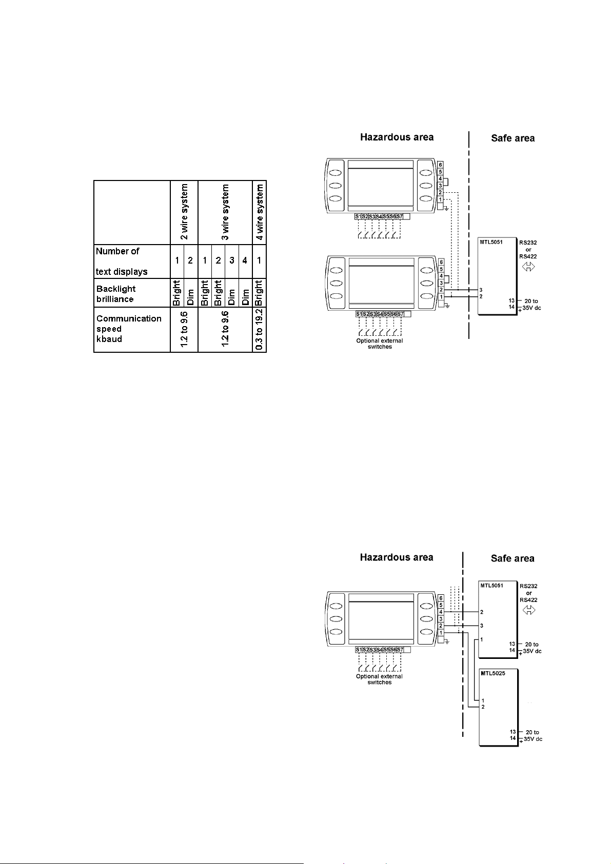
4. SYSTEM DESIGN FOR HAZARDOUS
AREAS
There are three configurations that may be
used for hazardous area installations. The
choice depends upon how many text displays
are required, the backlight brilliance and the
communication speed required. The following
table summarises the performance.
When two MTL646 text displays are multidropped from a common galvanic isolator the
brilliance of both display backlights will be
significantly reduced.
.
4.1 Cable length
The dc loop resistance of the cable between
the MTL646 and the associated galvanic
isolator in the safe area must not exceed 20Ω.
This applies for 2, 3 and 4 wire systems
irrespective of the number of text displays
connected to the loop. Most instrument cables
have a loop resistance of between 50 and
200mΩ per metre, thus limiting the maximum
cable length to between 100 and 400 metres.
The maximum permitted intrinsic safety cable
parameters specified on the system certificates
must also not be exceeded. However, in
practice only the capacitive limit in IIC gases is
likely to be restrictive.
Communication speed will also limit the
transmission distance. At 9.2k baud a
screened twisted pair should provide reliable
communication up to 100 metres. If data
corruption occurs the communication speed
should be reduced.
4.2 Two wire system
This is the simplest and probably the most
frequently used system. One or two MTL646
serial text displays are connected to a
MTL5051 in the safe area via two wires that
provide both power and bi-directional
communication.
Fig 2 shows the wiring diagram that is defined
by ITS System Certificate Ex03E21194.
With this configuration data may be transmitted
and received at 1.2, 2.4, 4.8 or 9.6kbaud.
Fig 2 Two wire system
4.3 Three wire system
The three-wire system illustrated in Fig 3 can
be used for multidrop applications. Up to four
MTL646 serial text displays may be powered
and addressed but, if more than two are used,
the backlight brilliance of all the displays will be
significantly reduced.
With this configuration data may be transmitted
and received at 1.2, 2.4, 4.8 or 9.6kbaud.
ITS System Certificate Ex03E21195 defines
this system.
Up to three
MTL646
Fig 3 Three wire system
4
Page 9
4.4 Four-wire system
The four-wire system, which is defined by ITS
System Certificate Ex03E21196, allows
communication at higher and lower rates than
the other two configurations. It should be used
for applications requiring fast display updates,
or with slow data rates when long cable runs
are required. The four-wire system does not
support multidrop operation.
Data may be transmitted and received at 0.3,
0.6, 1.2, 2.4, 4.8, 9.6 and 19.2kbaud.
MTL646
Fig 4 Four wire system
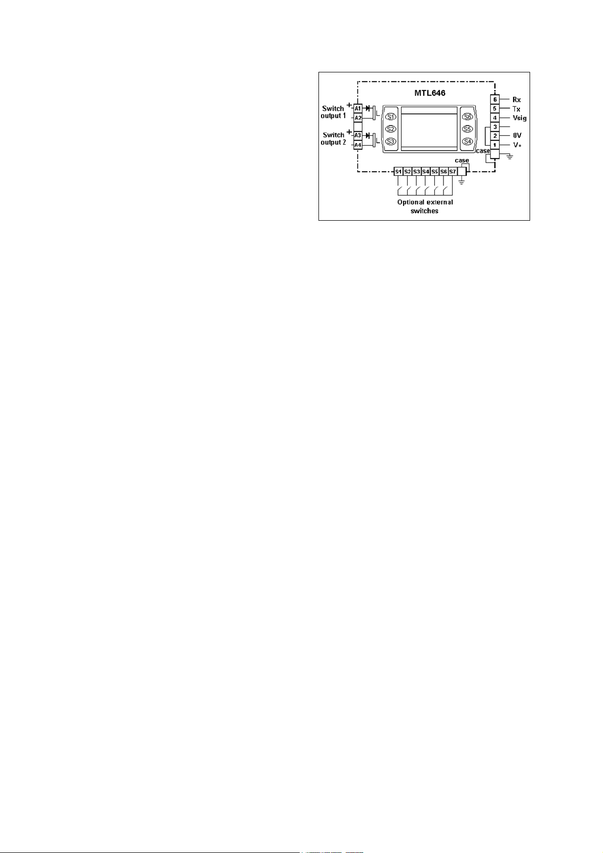
4.5 Switch outputs
Each switch output is a galvanically isolated
single pole solid state switch output as shown
in Fig 5.
5. INSTALLATION
5.1 Location
The MTL646 is housed in a robust aluminium
enclosure with a toughened glass window
mounted in a Noryl bezel. The front of the
instrument provides IP65 protection and a
gasket seals the joint between the instrument
enclosure and the panel. The instrument may
be installed in any panel providing the
environmental limits shown in the specification
are not exceeded.
Fig 6 shows the overall dimensions of the
MTL646 and the panel cut-out. To achieve an
IP65 seal between the instrument enclosure
and the panel, the smaller cut-out must be
used and the instrument secured with four
panel mounting clips.
The MTL646 liquid crystal display has
maximum contrast when viewed from directly
ahead and slightly below the centre line of the
instrument.
Fig 5 Equivalent circuit of each switch output
The outputs are polarised and current will only
flow in one direction. Terminals A1 and A3
should be connected to the positive side of the
supply.
R
R
= 5Ω + 0.6V
on
= greater than 1MΩ
off
Note: Because of the series protection diode,
some test meters may not detect a closed
alarm output
WARNING
These switch outputs should not be
used for critical safety applications
such as an emergency shut down
system.
When the MTL646 power supply is turned off
or disconnected, both MTL646 switch outputs
will open irrespective of how they have been
programmed.
Fig 6 MTL646 dimensions
5
Page 10
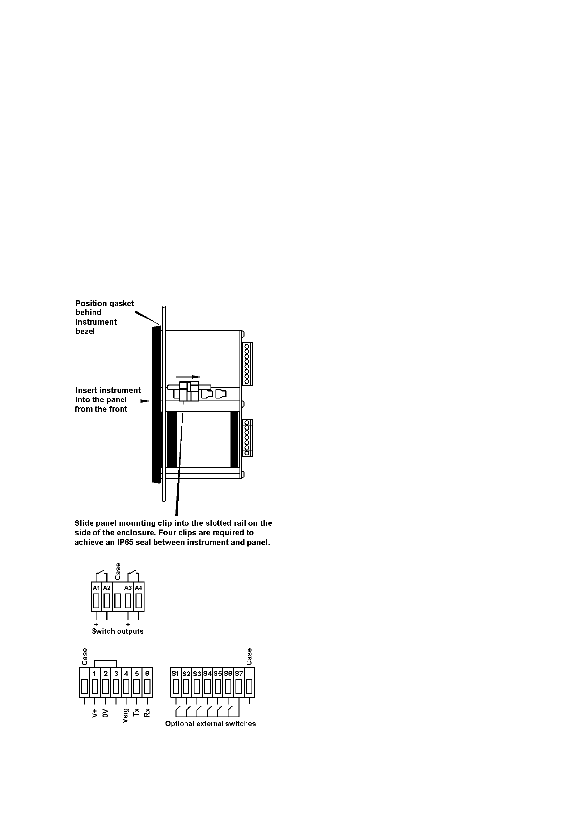
5.2 Installation Procedure
a. Insert the MTL646 into the instrument
panel cut-out from the front of the
panel.
b. Fix panel mounting clips to opposite
sides of the instrument and tighten until
the instrument is secure as shown in Fig
7. Four clips are required to achieve an
IP65 seal between the instrument
enclosure and the panel.
c. Connect the panel wiring to the rear
terminal block(s) as shown in Fig 7. To
simplify installation, the terminals are
removable so that panel wiring can be
completed before the instrument is
installed.
5.3 EMC
The MTL646 complies with the requirements of
the European EMC Directive 89/336/EEC. For
specified immunity all wiring should be in
screened twisted pairs.
To prevent circulating currents, cable screens
should only be earthed at one point in the safe
area.
Fig 7 Installation and terminal connections
6
Page 11

6. CONFIGURATION
Before the MTL646 can be commissioned it
must be configured to be compatible with the
host’s communications format and have the
required functions enabled.
The MTL646 is configured via four of the front
panel push-buttons. All the configuration
functions are contained in an easy to use menu
shown in Fig 8. Where necessary the submenus contain on-screen prompts to guide the
user through each adjustment.
When navigating through the configuration
menu, the push-button(s) should be held until
the required screen is displayed.
6.1 Default configuration
Unless otherwise requested at time of ordering,
MTL646 text displays will be supplied
configured as follows:
Baud rate 9.6k
Data bits 8
Stop bit 1
Parity None
Protocol MTL
Units Single
Address 0
Operational mode 1
Keypad Internal
Display brightness 50%
Display contrast 50%
Limit backlight On
Quick access menu On
Quick access menu code 0000
Configuration menu
access code. 0000
6.2 Accessing the configuration menus
Throughout this manual push-buttons are
shown in italics e.g. P or Up push-button, and
legends displayed by the instrument are shown
within inverted commas e.g. 'Please enter
code'.
The configuration menu is accessed by
operating the P and E push-buttons
simultaneously. Fig 6 shows the location of
these push-buttons. If the MTL646 is not
protected by an access code the main menu
will be displayed. If an access code other than
the default code 0000 has already been
entered, the MTL646 will request that the
access code be entered.
Using the Up or Down button set the first digit
of the code which will be flashing. Pressing P
will transfer control to the next digit, which
should be adjusted in the same way. When all
four digits have been set, pressing the E button
will enter the access code. If the code is
correct the main menu will be displayed, if the
code is incorrect ‘Invalid access code’ will be
displayed.
When entering an access code, timeout will
occur and the instrument will automatically
return to the operating mode ten seconds after
the push-buttons were last operated. In all
other menus timeout occurs after thirty
seconds.
When the main menu is displayed the required
sub-menu can be highlighted by scrolling
through the menu using the Up or Down pushbutton. Operating the P push-button will
display the highlighted sub-menu from which a
further selection may be made. After a
configuration parameter has been adjusted,
pressing the E button will enter the selection
and move the display up one level.
After configuration has been completed,
operating the E push-button repeatedly will
return the instrument display to the main menu.
One more operation of the E button will then
return the MTL646 to the operating mode.
6.3 Summary of configurable functions
This section provides a brief explanation of
each configurable function and should be read
in conjunction with Fig 8.
View settings
Displays the instruments main
communication settings.
Baud rate
Data rate may be set to seven speeds
between 0.3 and 19.2kbaud. Allowable
rates depend upon the system in which the
MTL646 is used.
Data bits
7 or 8 data bits may be selected. 8 bit data
is required in MTL mode for graphics and
error checked modes
Stop bits
1 or 2 stop bits may be selected.
Parity
An even, odd or no parity bit may be
selected.
Protocol
MTL646/7 or legacy MTL643/4 protocol
may be selected. The Legacy protocol is
compatible with the MTL644.
Units
Selects single or multiple MTL646 displays
connected to a single MTL5051.
7
Page 12

Address
For multidrop applications each text display
must be allocated a unique non-zero
address. Addresses may be set between 1
and 15. For single text display applications
the MTL646 address should be set to 0.
Operational mode
Five levels of communications security may
be selected, ranging from immediate
execution of a command with no
acknowledgement, to a requirement for a
16 bit cyclic redundancy check. See
section 7 and the programming guide for a
detailed explanation.
This function is not available when Legacy
protocol is selected.
Keypad
This function allows the instrument front
panel push-buttons or external pushbuttons to be used for operator inputs.
Whichever are selected, the instrument
front panel push-buttons are used for
configuration.
This function is not available when Legacy
protocol is selected.
Display settings
Allows the backlight brightness and contrast
of the MTL646 display to be adjusted.
Limit backlight
When ‘On’ is selected the maximum
backlight brightness will be automatically
set depending upon whether a ‘Single Unit’
or ‘Multiple Unit’ has been selected in the
configuration menu.
When ‘Off’ is selected the automatic
brilliance limit is overridden for special
applications, e.g. two text displays on a
three-wire system.
Quick access menu
This function enables the quick access
menu described in section 6.4. When ‘On’
is selected an operator can adjust the
screen brilliance and contrast without
having access to other conditioning
parameters.
Access code for the Quick Access Menu
Defines the four digit alphanumeric code
that must be entered to gain access to the
instrument’s quick access menu. Alpha
characters are case sensitive. Default
code 0000 allows direct access without a
code.
Access code for the Configuration Menu
Defines the four digit alphanumeric code
that must be entered to gain access to the
instrument configuration menus. Apha
characters are case sensitive. Default
code 0000 allows direct access without a
code.
Unit information
Displays the instrument model number and
the software version.
Configuration defaults
This function allows the configuration
default defined in section 6.1 to be globally
set.
6.4 Quick Access Menu
The quick access menu allows an operator to
adjust the backlight brilliance and the display
contrast without having access to the other
configuration parameters.
The quick access menu is accessed by
operating the P and Up push-buttons
simultaneously. Fig 6 shows the location of
these push-buttons. If the quick access menu
is not protected by an access code the
brilliance and contrast controls will be
displayed immediately. If an access code
other than the default code 0000 has already
been entered, the MTL646 will request that the
access code be entered. Section 6.2 explains
how an access code should be entered.
The backlight brilliance is adjusted using the
Up and Down push-buttons. Operating the P
push-button will transfer control to the display
contrast adjustment. When both are set as
required operating the E button will store both
settings and return the instrument to the
operating mode.
8
Page 13

MTL
Display mode
MTL646/7
MTL643/4
9
Page 14

7. PROGRAMMING
A detailed description of the MTL programming
protocol, together with examples of all the
instructions, are contained in the MTL646 &
MTL647 Programming Guide which may be
downloaded from the MTL web site at
www.mtl-inst.com
summary of the MTL protocol and instruction
set.
This manual only includes a
7.1 Summary of MTL protocol
• Pure ASCII protocol except for graphics
downloads, checksums and CRCs.
• Commands are two characters, case
insensitive, enclosed in angled brackets.
• Some commands require parameters.
Parameters follow the command directly.
Multiple parameters are separated by
commas. A command and its parameters
are enclosed within a single set of angled
brackets.
• All attribute commands are active until
overridden by another command.
• No spaces are allowed in
commands/parameter strings. (except in
the WT write text command)
• Any characters not enclosed in angled
brackets are written directly to the screen
at the current cursor position (operational
mode < 2). If angle brackets are required
in text, two consecutive brackets may need
to be sent depending upon operational
mode.
• Any detected parameter error causes the
command to be rejected.
• The instruments’s response to received
messages is programmable. Modes are:
No response.
Response to every correctly formatted
command.
Response to a set of correctly
formatted commands.
• Status of operator switches is encoded into
the returned message, or can be explicitly
requested.
• Communications error checking is
programmable. Modes are:
No error checking
Simple checksum
16bit Cyclic Redundancy Check.
7.2 Command format
<AB[param1],[param2]>
where:
AB is the command.
[..] indicates optional parameters
separated by commas.
examples:
<CM4,90> Cursor Move to Row 4
Column 90
<CS> Clear Screen
7.3 Response format
Ka or Ea or ?a or P0
where:
K indicates that the previous
command/command set has been
accepted.
E indicates a parameter or
communications error has been
detected in the previous command
string.
? indicates that the command is
unrecognised.
P indicates that a message has been
received but NOT actioned because the
instrument is in the conditioning mode
10
Page 15

a returns the key status
0=no key pressed
1=key1
2=key2
3=key3
4=key4
5=key5
6=key6 pressed
examples:
K0 Command accepted, no keys
pressed.
E1 Command error detected,
key 1 pressed.
?6 Command unrecognised, key
6 pressed.
P0 Command rejected,
instrument in conditioning
mode.
7.4 Operational Modes
The operational mode is defined in the
conditioning menu, see section 6.3
Mode 0:
Commands are executed immediately,
no reply message. Plain text is written
directly to the screen, no reply
message.
Mode 1:
Commands are executed immediately,
a response is returned to each
command. Plain text is written directly
to the screen, no reply message.
Mode 2:
Multiple commands can be sent, but
these are not executed until a
“Command Implement” <CI> command
is sent. One reply is returned for each
set of commands. An error in any of
the commands will result in a
Command Error response. Plain text
is ignored.
Mode 3:
As Mode 2 but the <CI> command is
replaced by a <CCn> command where
n is a single byte simple checksum of
all characters sent (including spaces)
up to, but not including the <CCn>
command. The response has a similar
single byte checksum appended to the
end of the response. The command
string is not actioned if the checksum
of the data received does not match
the parameter of the <CCn>
command. Plain text is ignored.
Mode 4:
As Mode 3 but the <CCn> is replaced
by <CRnn> where nn is a 16-bit CRC
code.
7.5 Multidrop Operation
Multidrop operation is possible. Unique unit
addresses > 0 need to be set on each
instrument.
Command <MCn> (Make Connection) is used
to define the address (n) to which subsequent
commands are directed.
Command <RC> disconnects the currently
‘connected’ unit
11
Page 16

7.6 Summary of Commands
Commands are listed in functional groups. Detailed descriptions of each command including
examples of how they should be used are included in the MTL646 & MTL647 Programming Guide
which may be downloaded from www.mtl-inst.com
7.6.1 Screen handling and text
Command Meaning Description
<CLn>
<CMy,x>
<CS> Clear Screen All pixels off, cursor homed
<CW>
<EL>
<FS> Fill Screen All pixels on, cursor homed
<FW>
<HC>
<LN>
<RS>
<SD>
<WSn>
<WTthis is a message> Write Text Sends text and ensures a response
Clear Line
Cursor Move
Clear Window
Erase Line
Fill Window
Home Cursor
Line New
Request Status
Screen Defaults
Write Soft
character
Erases all text on line n. For
parameter ranges see CM
command. Row Mode only.
Cursor moved to Row y Column x.
Row values are 0-7 (Row Mode), 063 (Pixel Mode) Column values are
0 – 119.
All pixels set to off in the defined
window area. Cursor homed in the
windowed area.
Row Mode only
Erases text from current cursor
position to end of line.
Row Mode only.
Sets all pixels in the defined
window ‘on’. Cursor Homed in the
windowed area.
Row Mode only
Returns the cursor to the top left of
the screen for the current font. This
command is window aware in Row
Mode
Sends a carriage return and line
feed to the display so that following
text is written on the next line down.
Row Mode only.
Returns switch status when
operating in Mode 0.
Works in any mode.
Returns the instrument screen to
default state. See definition at the
end of this table.
Write Soft character n. n=0-3. This
command displays the previously
downloaded soft character at the
current cursor position. It will
assume all of the currently active
attributes, just as any normal
character. Command is active in
both Row Mode <RM> and Pixel
Mode <PM>. Soft fonts are lost
when power is removed. Soft fonts
F1 to F4 can be saved to eeprom.
and restored. See <KF> and <FR>
commands.
from the instrument Operational
Mode OM>0.
12
Page 17

Note: The Screen Defaults <SD> command returns the display and its attributes to a kn own state
listed below.
Display scroll off
Key press data cleared
Window definition cleared
<VF0> Visible frame = 0
<AF0> Active frame = 0
<F1> Small font 8 x 6 Pixels
<CS> Clear Screen
<HC> Cursor homed
<WM0> Normal text
<RM> Row Mode
<IF> Inhibit Flashing
<ST> Text Steady attribute
<NA> No text Alignment
<BM0> Background Mode = 0
<NU> No Underline
7.6.2 Attributes
Command Meaning Description
<BMn>
<CA>
<DWyt,yb,xl,xr>
<EF> Enable Flashing Enables flashing for characters
<F1> Font 1 6 mm high 8 x 6 pixels.
<F2> Font 2 10 mm high 16 x 10 pixels.
<F3> Font 3 17 mm high 24 x 15 pixels.
<F4> Font 4 23 mm high 32 x 19 pixels.
<F5>
<FL> Flash Following text flashing
<IF> Inhibit Flashing Stops flashing on the whole display.
Background
Mode
Centre Align
Define Window
Font 5
If n=0, flash background is pixels off
If n=1, flash background is pixels on
If n=2, flash background is the
inverse of the character or graphic
being written.
Default state is <BM0>.
To use this command, the flashing
attribute <FL> must be set. To
enable screen flash the Enable
flash <EF> command must be sent.
Text is centred (x-direction). Use
with <WT> command.
Window aware in Row Mode only.
Creates a sub-window for text .
yt=top row, yb=bottom row, xl=left
column, xr=right column.
Row Mode only
written with the flashing attribute set
Cursor is homed.
Cursor is homed.
Cursor is homed.
Cursor is homed.
34 mm high 48 x 29 pixels.
Partial Character set only (0-9, A-Z,
space, comma, full-stop, plus,
minus). Undefined characters not
trapped. Cursor is homed.
Overrides attributes
13
Page 18

14
Page 19

Command Meaning Description
<LA>
<LF> Line Feed Line feed added after carriage
<NA>
<NL>
<NU>
<RA>
<ST> Steady Following text non-flashing
<SW>
<TW>
<UL>
<WMn> Write Mode 0=Normal, 1=OR, 2=XOR,
Left Align
No Align
No Linefeed
No Underline
Right Align
Smart Wrap
Text Wrap
UnderLine
Text is left justified. Use with <WT>
command.
Window aware in Row Mode only.
return. Row Mode only
Text is written at the current cursor
position by the <wt> command.
This is the default setting.
Carriage return and line feed are
independent actions. Row Mode
only
Cancels the <UL> command above
Text is right justified. Use with
<WT> command.
Window aware in Row Mode only.
Wraps text onto next line, does not
break words. Use with WT
command. Row Mode only.
Cancelled by any subsequent text
alignment command.
Characters are wrapped on to the
next line at the end of the line in the
current window. Row Mode only.
Cancelled by any subsequent text
alignment command.
Text in fonts F2 to F5 is underlined
in the decender area of the current
font. Underlining can be used in
both row and pixel modes.
3=Inverse
15
Page 20

7.6.3 System commands
Command Meaning Description
<AFn>
<CCn>
<CI>
<CE>
<CP> Configuration
<CRnn>
<DFn>
<FR>
<HSmnrstuv>
<KF> Keep Fonts Soft fonts F1 to F4 are saved to
Active Frame
Check Code
Command
Implement
Configuration
Enable
Prohibit
Cyclic
redundancy
check
Download Font
Font Restore
Horizontal Scroll
Subsequent writes to the
instrument are written to page
frame n. n=0 or 1. Default is 0.
Specifies a simple checksum (n) of
a previously sent command string.
Operational Mode 3.
Signal to execute previously sent
commands.
Operational Mode 2.
Entry to the menu structure by the
dual P-E keypress is enabled. This
is the default state.
Entry to the menu structure by the
dual P-E keypress is inhibited.
Specifies a 16-bit CRC (nn) of a
previously sent command string.
Operational Mode 4.
Download soft character n for the
currently active font. (n=0-3) After
this command has been issued a
binary download of a .BPM file is
expected. This file must be an
image exactly the same size (in
pixels) as the currently active font.
An image of any other size will
cause an error response. The
mechanism and .BMP file
requirements for this command is
exactly the same as that for the
Download Graphic <DG> and
Download Logo <DL> commands.
Soft fonts F1 to F4 are recovered
from eeprom. This will overwrite
any downloaded fonts that have not
been saved using the <KF>
command above.
m= 0 scroll is Right to Left,
m=1 scroll is Left to Rright.
n=Start row of block to scroll
r=Last row of block to scroll
A line of length t pixels starting at
Pixel=s above the bottom of row r
and a line of length v pixels starting
at Pixel=u above the bottom of row
r is inserted For Left to Right scroll,
the line is inserted at the left of the
screen, for Right to Left scroll at the
right of the screen.
This is a row mode command that
can be used in a window. If it is
used in a window, then the
parameters are relative to the
defined window.
Eeprom.
16
Page 21

Command Meaning Description
<MCn>
<ODn> Switch Output
<OEn> Switch Output
<PM> Pixel Mode Text is pixel aligned. Any defined
<RB> ReBoot Hardware restart activated by
<RC>
<RFm>
<RLx>
<RM> Row Mode Text is row aligned.
<SBn> Set Backlight Backlight set to intensity n=0 to
<SFnm> Save Frame Saves frame ‘m’ to memory area
<SL>
<TOn>
<VFn>
Make
Connection
De-energised
Energised
Release
Connection
Restore Frame
Restore Logo
Save Logo
Time Out
Visible Frame
Subsequent commands are
addressed to the stated node. n=1
to n=15.
Output n open circuit. n=1 or n=2.
Output n short circuit. n=1 or n=2.
windows are cleared.
deliberate watchdog timeout.
Releases the connection made with
the <MC> command above. After
this command, no instruments will
respond until a further <MCn>
command is issued.
Restores the frame saved with
<SF> to the current active frame.
Attributes are not restored
User defined logo is written to the
current visible frame. x=0 gives a
static display, x=1 enables scrolling
of the logo as at power-up. If there
is no user logo saved, the MTL logo
is displayed.
n=40.
‘n’.
The visible frame is saved to
eeprom and used as a power-up
logo to replace the MTL logo.
Command takes about 2 seconds
to complete. Saving a blank screen
re-enables the MTL logo. Intended
to be used in conjunction with the
<DL> command, but any screen
image can be saved.
Flashes a warning message on the
screen when no communication is
received for n x 10 seconds. n=0
disables the timeout function.
Default is disabled.
Page frame n is made visible. n=0
or 1. Default is 0. Cursor positions
are not saved or restored with
frames.
17
Page 22

7.6.4 Line graphics
Command Meaning Description
<BDylength,xlength,lwidth>
<HBnm>
<LHxlength, lwidth>
<LVylength, lwidth>
<VBnm>
Box Draw
Horizontal
Bargraph
Line Horizontal
Line Vertical
Vertical
Bargraph
Draws a box y length pixels high, x
length pixels wide, and with a line
width of l width pixels, from the
current cursor position (up and to
the right). Parameters can be any
value that will keep the box being
drawn on screen. Pixel Mode only.
Draw a horizontal bargraph from
the current cursor position.
n=length, m=fill both in pixels.
Row Mode only
Draws a horizontal line x length
pixels long, l width pixels wide from
the current cursor position (up and
to the right). The line length and
line width can be any value that will
keep the line being drawn on
screen. Pixel Mode only
Draws a vertical line ylength pixels
long, lwidth pixels wide from the
current cursor position (up and to
the right). The line length and line
width can be any value that will
keep the line being drawn on
screen. Pixel Mode only
Draw a vertical bargraph from the
current cursor position. n=length,
m=fill both in pixels. Row Mode only
18
Page 23

7.6.5 Pixel graphics
Command Meaning Description
<DG>
Download
Graphic
Command is followed by a .BMP file
download. See Graphics Download
section. Pixel Mode only.
<DS>
<UE> Upload Enable
<US> Upload Screen
7.7 Graphics Downloads.
The protocol is extended as follows to cover
the two simple graphics download commands
<DG> and <DS>
7.7.1 <DS> command
• Command <DL> is issued with any
additional bytes (checksum, CRC etc) as
required by the current operational mode.
• Command is acknowledged if correctly
received.
• A binary download of the .BMP file is then
expected. After the file has been
downloaded, the <CI>, <CCn> or <CRnn>
command must be sent as per the current
operational mode. “n” represents the
simple checksum of all the bytes in the
.BMP file, “nm” represents the 16-bit CRC
of all the bytes in the .BMP file
• The download is acknowledged if correctly
received (including checksum or CRC
checks).
Download
Screen
Command is followed by a .BMP file
download. See Graphics Download
section.
Enables the screen dump command
above. Needs to be sent
immediately prior to the <US>
command.
Sends a screen image back to the
user as a .bmp file. The <US>
command is acknowledged in the
normal way. After a short gap
(25ms), a 1086 byte block of data is
sent. A command acknowledge is
then sent with the check bytes as
per the current operational mode.
The check bytes include the data
block bytes and the
acknowledgement, but not the check
bytes themselves. The data block,
saved to file is a graphics image of
the screen.
• There is a 2 second timeout for the
download operation. If no bytes are
received in this time, the download is
aborted and an error response is returned.
• The downloaded logo is then displayed.
The image must be exactly 120x64 pixels
and two colour (black and white) in
standard Windows (OS2) format. An error
response is returned if these requirements
are not satisfied.
7.7.2 <DG> command
• Command <DG> follows exactly the same
mechanism as the <DS> command above,
but any size of image can be sent up to
120x64. Files in excess of this size will
cause an error response.
• The display must be in Pixel Mode <PM>
and the downloaded image is displayed at
the current cursor position.
• The image dimensions are computed from
the .BMP file sent.
19
Page 24

• The image is drawn upwards from and to
the right of the current cursor position. If
any part of the image exceeds the display
bounds the image is NOT displayed and
an error response is returned.
• The .BMP format must still be two colour,
standard Windows (OS2) format. An error
response is returned if these requirements
are not satisfied
• The downloaded image adopts the display
attributes currently in force (Normal, OR,
XOR, Inverse, Flashing, Steady)
Note:
1. The <DS> command is just a special case
of the <DG> command but because of its
fixed size is executed much more quickly.
2. Graphics can be downloaded to a hidden
frame using the <VF> and <AF>
commands and then made visible when
complete.
7.8 Cyclic Redundancy Check
The 16-bit CRC used in the protocol is the
same as used for the well-known Modbus
Protocol. Details are as follows:
The CRC is started by first preloading a 16-bit
register to all 1's. Then a process begins of
applying successive eight-bit bytes of the
message to the current contents of the
register. Only the eight bits of data in each
character are used for generating the CRC.
Start and stop bits, and the parity bit, do not
apply to the CRC.
During generation of the CRC, each eight-bit
character is exclusive ORed with the register
contents. The result is shifted in the direction
of the least significant bit (LSB), with a zero
filled into the most significant bit (MSB)
position. The LSB is extracted and examined.
If the LSB was a 1, the register is then
exclusive ORed with a preset, fixed value
(A001 hex). If the LSB was a 0, no exclusive
OR takes place.
This process is repeated until eight shifts have
been performed. After the last (eighth) shift,
the next eight-bit character is exclusive ORed
with the register's current value, and the
process repeats for eight more shifts as
described above. Finally, the content of the
register, after all the characters of the
message have been applied, represents the
CRC value.
20
Page 25

7.8.1 Procedure for generating a CRC
Step 1 Load a 16-bit register with FFFF hex
(all 1's). Call this the CRC register.
Step 2 Exclusive OR the first eight-bit byte
of the message with the low order
byte of the 16-bit CRC register,
putting the result in the CRC register.
Step 3 Shift the CRC register one bit to the
right (toward the LSB), zerofilling the
MSB. Extract and examine the LSB.
Step 4 If the LSB is 0, repeat Step 3
(another shift). If the LSB is 1,
Exclusive OR the CRC register with
the polynomial value A001 hex (1010
0000 0000 0001).
Step 5 Repeat Steps 3 and 4 until eight
shifts have been performed. When
this is done, a complete eight-bit byte
will have been processed.
Step 6 Repeat Steps 2 to 5 for the next
eight-bit byte of the message.
Continue doing this until all bytes
have been processed.
Step 7 The final contents of the CRC
register is the CRC value.
This CRC value is then appended to the
message. The LSB of the CRC is sent first
followed by the MSB.
21
Page 26

8. MAINTENANCE
8.1 Fault finding during commissioning
If a MTL646 fails to function during
commissioning the following procedure should
be followed:
Symptom Cause Check:
No Display No Power
No
Communication
Poor
Communication
Dark Display Contrast too high Contrast level in
No Backlight
or
Backlight dim
Cannot enter
configuration
menu
Communications
MTL646 displays
Push-buttons not
Incorrect wiring
parameters
incorrectly set
Incorrect
Protocol
Incorrect wiring Wiring is as per
Address
Incorrect in
Multidrop Mode
Too many
on the line.
Lines too long
Communication
speed too fast.
Backlight off or
set low
or
Multidrop mode
in use
held for long
enough (up to 2
seconds
required)
Menu inhibited
That there is 10
to 14 volts
between terminal
1 and 2 of the
seven way
connector.
Terminal 1
should be
positive.
Baud rate, data
bits, stop bits and
parity settings
match those of
the host.
Configuration
switches on the
communcations
isolator.
Protocol settings
in “Comms”
Menu
diagrams for the
chosen
configuration
Address setting
in “Comms”
menu
Configuration
settings.
Installation
guidelines
“Display
Settings” menu
Brightness level
in “Display
Settings” menu
Units setting in
“Comms” menu
Send “Program
Enable”
command (MTL
mode)
Restart unit
(Legacy mode)
8.2 Fault finding after commissioning
ENSURE PLANT SAFETY BEFORE
STARTING MAINTENANCE
Live maintenance is permitted on
intrinsically safe equipment installed
in a hazardous area, but only certified
test equipment should be used unless
a gas clearance certificate is available.
If a MTL646 fails after it has been functioning
correctly, the table shown in section 8.1 may
help to identify the cause of the failure.
If this procedure does not reveal the cause of
the fault, please contact MTL or our local
agent.
8.3 Servicing
We recommend that faulty MTL646 serial text
displays are returned to MTL or to our local
agent for repair.
8.4 Routine maintenance
The mechanical and electrical condition of the
instrument should be regularly checked.
Initially annual inspections are recommended,
but the inspection frequency should be
adjusted to suit the environmental conditions.
8.5 Guarantee
Instruments that fail within the guarantee
period should be returned to MTL or our local
agent. It is helpful if a brief description of the
fault symptoms is provided.
8.6 Customer comments
MTL is always pleased to receive comments
from customers about our products and
services. All communications are
acknowledged and whenever possible,
suggestions are implemented.
22
Page 27

9. ACCESSORIES
9.1 Tag number
The MTL646 can be supplied with a thermally
printed tag number on the rear panel. This tag
number is not visible from the front of the
instrument after installation.
9.2 MTL646 & MTL647 Programming Guide
A detailed guide to programming the MTL646
and MTL647 serial text displays may be
downloaded from the MTL website at
www.mtl-inst.com
23
Page 28

10. INDEX
Subject Section
Address 6.3
ATEX Directive 3.1; 3.7
Backlight 4, 4.2, 4.3,
6.1, 6.4
MTL protocol 2.1
Cable
Length 4.1
Parameters 3.5, 3.6, 4.1
Certificates
EC-Type Examination 3.1
Label 3.7
system 3.2
Communication speed 4.
Configuration 6.
Access 6.2
Default settings 6.1
Structure Fig 8
Quick access menu 6.4
EMC 5.3
External switches 3.5
Fault finding
During commissioning 8.1
After commissioning 8.2
Galvanic isolators 3.4
Gas groups 3.3
Guarantee 8.5
Installation 5.2
Intrinsic safety 1; 3; 4
Legacy protocol 2.2
Location 5.1
Maintenance 8.
Routine 8.4
Multidrop 2. 4.2, 4.3, 4.4,
7.5
Subject Section
Notified Body 1
MTL644 display 2.2
MTL5051 galvanic isolator 3.4, 4.2, 6.3
Power supply 3.4
Programming 7.
Commands
Attributes 7.6.2
Line graphics 7.6.4
Pixel graphics 7.6.5
Screen handling 7.6.1
System 7.6.3
Command format 7.2
Cyclic Redundancy
check. 7.8, 7.8.1
Guide 2, 9.2
Operating modes 7.4
Response format 7.3
Summary of MTL
protocol. 7.1
Servicing 8.3
Switch outputs 3.6
Systems
2-wire 4.2
3-wire 4.3
4-wire 4.4
Certificates 3.2
T rating 3.3
Terminal numbers Fig 7
Zones 3.3
24
Page 29

Modifications
8 June 2003 Issue: 1
25
Page 30

Page 31

MTL Instruments Pty Limited
1/30 Canvale Road
Canning Vale
Perth, WA 6155
Australia
Tel: +61 (0)8 9455 2994 Fax: +61 (0)8 9455 2805
E-mail: enquiries@mtlaus.com.au
MTL Canada Safety Instrumentation
#102, 4249 97 Street
Edmonton, Alberta
Canada T6E 5Y7
Tel: +1 780 485 3132 Fax: +1 780 485 3122
E-mail: cinfo@mtlnh.com
MTL Instruments Pte
Room 1002A, The Gateway
No 10 Yabao Road, Chaoyang District
Beijing 100020
China
Tel: +86 010 8562 5718/5720/5721 Fax: +86 010 8562 5725
E-mail: bjsales@mtl-inst.cn
MTL Instruments sarl
Les Carrés du Parc
10 rue des Rosiéristes
69410 Champagne au Mont d’Or
France
Tel: +33 (0)4 78 64 98 32 Fax: +33 (0)4 78 35 79 41
E-mail: info@mtl-inst.fr
MTL Instruments GmbH
An der Gümpgesbrücke 17
D-41564 Kaarst
Germany
Tel: +49 (0)2131 718930 Fax: +49 (0)2131 7189333
E-mail: info@mtl.de
MTL India Pvt. Limited
No. 36, Nehru Street
Off Old Mahabalipuram Road
Sholinganallur
Chennai - 600 119
India
Tel: + 91 (0)44 24501660/24501857 Fax: + 91 (0)44 24501463
E-mail: sales@mtlindia.com
MTL Italia srl
Via Cantù 11
I - 20092 Cinisello Balsamo MI
Italy
Tel: +39 (0)2 61802011 Fax: +39 (0)2 61294560
E-mail: info@mtl-inst.it
MTL Instruments KK
3rd Floor, Gotanda Masujima Building
1-8-13 Higashi-Gotanda, Shinagawa-Ku
Tokyo 141-0022
Japan
Tel: +81 (0)3 5420 1281 Fax: +81 (0)3 5420 2405
E-mail: sales@mtlkk.co.jp
MTL Instruments BV
PO Box 55, 6680 AB Bemmel
de Houtakker 36, 6681 CW Bemmel
The Netherlands
Tel: +31 (0)481 450250 Fax: +31 (0)481 450260
E-mail: info@mtlbenelux.com
MTL Instruments Pte Limited
31 Ubi Road 1
#04-01 Aztech Building
Singapore 408694
Tel: +65 6 487 7887 Fax: +65 6 487 7997
E-mail: sales@mtlsing.com.sg
MTL Instruments
Villa No. 4, Sector 2-17, Street 6
PO Box 53234,
Abu Dhabi, UAE
Tel: +971 2 446 6840 Fax: +971 2 446 6841
E-mail: mtlgulf@mtl-inst.com
Measurement Technology Limited
Power Court, Luton, Bedfordshire
England LU1 3JJ
Tel: +44 (0)1582 723633 Fax: +44 (0)1582 422283
E-mail: enquiry@mtl-inst.com
MTL Incorporated
4001 W. Sam Houston Parkway N. ,Suite 150
Houston TX 77043
USA
Tel: +1 281 571 8065 Fax: +1 281 571 8069
E-mail: info@mtl-inst.com
Group Internet home page http://www.mtl-inst.com/
Members of The MTL Instruments Group
 Loading...