

Page 1
EUROPE (EMEA) Tel: +44 (0)1582 723633 Fax: +44 (0)1582 422283
AMERICAS Tel: +1 603 926 0090 Fax: +1 603 926 1899
ASIA PACIFIC Tel: +65 487 7887 Fax: +65 487 7997
E-mail: enquiry@mtl-inst.com Web site: www.mtl-inst.com
Oct 2004
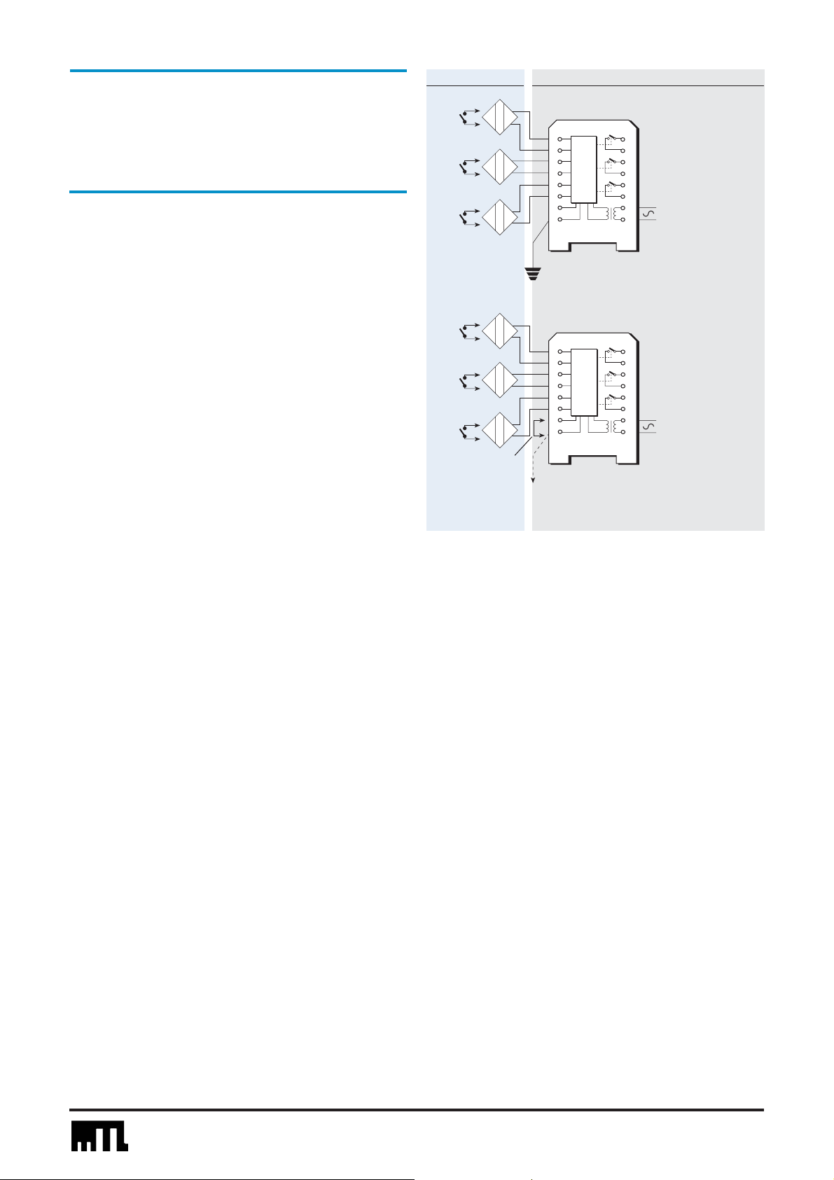
Load, alarm
or shutdown
circuits
No-fail protection
Link for phase
reversal
Fail-safe protection
MTL2213 SWITCH/
PROXIMITY DETECTOR
RELAY
3-channel
To MTL4220
(optional)
All contacts shown in alarm condition (relay de-energised)
The MTL2213 enables three 100VA safe-area loads to be controlled
independently by three light-duty on/off switches or certified proximity
detectors in a hazardous area. Switches and proximity detectors may
be mixed. The three input circuits are interconnected but fully floating.
For proximity-detector and some switch applications, a phase-reverse
link allows alarm conditions to be signalled for either state of the
sensors. ‘Alarm’ means relays de-energised with their on/off contacts
open, and all three circuits have to operate in the same fashion. This
compact low-cost unit is suitable for a wide variety of applications.
The MTL2213 supersedes the MTL2212 for which it is a direct
replacement, except that only terminal 8 can be used for connecting
to earth.
SPECIFICATION
See also ‘Common specification’
Number of channels
Three, interconnected, fully floating
Location of switches
Zone 0, IIC, T6 hazardous area
Div 1, Group A, hazardous location
Location of proximity detectors
Zone 0, IIC, T4–T6 if suitably certified
Div 1, Group A, hazardous location
Voltage applied to each sensor
7.7 to 9.0V dc from 1kΩ
Input/output characteristics (each channel)
Relay energised if >2.1mA* (<2kΩ) in sensor circuit
Relay de-energised if <1.2mA* (>10kΩ) in sensor circuit
Hysteresis: 200µA (650Ω ) nominal
*NAMUR and DIN 19234 standards for proximity detectors
Phase reverse facility
Operation of all 3 relays reversed by linking terminals 7 & 8
Power supply failure protection
All three relays de-energised, contacts open, if supply fails
Broken line protection (each channel, normal phase only)
Relay de-energised, contacts open, if either line broken
Fail-safe earth fault protection (each channel, normal
phase
only)
(Enabled by connecting terminal 8 to earth)
Relay de-energised if <25Ω to earth, total for both lines
Relay not de-energised if >52kΩto earth, total for both lines
‘No-fail’ earth fault protection (either phase)
(Enabled by connecting terminal 8 to MTL4220)
Fault on any line proclaimed: unit continues working
Response time (each channel)
50ms, nominal
Contacts (each channel)
On/off, open when relay de-energised
Contact rating
250V,5A,100VA (ac), resistive loads, reactive loads must be
suppressed
250V,5A,100W (dc), resistive loads, reactive loads must be
suppressed
Contact life expectancy
1.5 x 10⁵operations at maximum load
> 106operations at 200V ac peak or dc, 10VA (resistive load)
LED indicator (each channel)
ON when associated relay energised
Consumption
1.7 to 2.5W (ac versions)
110mA (24V dc version)
Ambient temperature limits
–20 to +50°C (ac versions, close packed)
–20 to +45°C (24V dc versions at 26V, close packed)
–20 to +60°C (all versions, at least 5mm apart)
–40 to +80°C (all versions, storage)
Safety description (each channel)
10.5V, 800Ω, 14mA
FM max entity parameters (each channel)
Voc= 10.5, Isc= 14.0mA, Ca= 3.0µF, La= 165mH
Load, alarm
or shutdown
circuits
L
N
L
N
Hazardous area
Safe area
+
1
2
+
3
4
+
5
6
7
8
+
1
2
+
3
4
+
5
6
7
8
9
10
11
12
13
14
15
16
9
10
11
12
13
14
15
16
}
+
–
}
+
–
 Loading...