

Page 1
• 18kA surge protection and RFI
filtering
• Protects panel loads up to 15 Amps in
series, unlimited Amps in parallel
• Suitable for AC or DC application
• Thermal and short circuit protection
• LED status indication feature
• 10 year product warranty
• UL1449 3rd Edition
technical datasheet
MA15 Series
AC and DC power surge suppressor and filter
The MA15 Series of surge protection devices
protects electronic equipment and computer
networks against the effects of ‘noise pollution’
induced in power supplies. MA15 units ‘clean
up’ the effects of industrial noise and surges
caused by lightning, switching devices, thyristor
controls, transmission system overloads and
power-factor correction circuits.
Industrial control systems utilizing
programmable logic controllers (plc) and
industrial computers are particularly vulnerable
due to the aggressive electrical environments for
which they are intended, such as process plants,
factories and water treatment sites. Although
industrial computers and plcs are designed to
be rugged, the extra protection provided by the
DIN rail mounting MA15 units is critical. Ideally
suited for protecting panel mounted equipment
and typically used in the controls section of a
motor control centre (MCC), the MA15 range
provides surge and RFI protected power.
With a unique ‘three-stage’ combination
of protection elements, these units suppress
conducted RFI and voltage surges. The circuit
elements are first, surge clipping components
to absorb transient surges that may otherwise
damage equipment, second a filter to suppress
noise in the system and third, ‘ring’ suppression.
The third of these prevents surges causing
the filter to ‘ring’ (oscillate) under low load
conditions – an effect that actually accentuates
interference in most commercially available
filters.
Suitable for AC or DC application, MA15
units reduce both electromagnetic emissions
and the susceptibility of the associated
equipment to emissions from other sources.
MA15 devices also offer ultimate installation
flexibility. To protect circuits rated 15A or less,
MA15 devices should be installed in series. To
protect higher current circuits, simply install the
MA15 in parallel.
An LED status indication facility is
standard with the MA15 units. This displays
both ‘power on’ and that protection is present.
Thermal fusing is also incorporated into each
18kA rated device as an additional safety
feature. MA15 units also offer short circuit
protection for added peace of mind.
MA15 devices are UL 1449 Recognized
Components (certified by UL for both US
and Canadian requirements) and exceed the
requirements of IEC 61000-4-5. As MA15 units
suppress conducted RFI and voltage surges they
enable associated equipment to comply with
this aspect of European ‘CE’ mark standards.
901-108 Rev J 110511
www.mtl-inst.com enquiry@mtl-inst.com
Page 2
SPECIFICATION
All figures typical at 77°F (25°C) unless otherwise stated
Maximum surge current
18kA (8/20µs) per mode
Maximum leakage current
<0.3mA
Maximum continuous operating current
120V @ 15A 240V @ 10A series connection
Unlimited Amps in parallel
Working voltage
AC DC
MA15/D/1/SI 120V, 47-63Hz 140V
MA15/D/1TT/SI 120V, 47-63Hz 140V
MA15/D/2/SI 240V, 47-63Hz 280V
MA15/D/2TT/L 240V, 47-63Hz 280V
Maximum continuous operating voltage
25% above nominal
Limiting voltage
@ 500A ring
120V/140V versions 295V
240V/280V versions 356V
@ 500A 8/20µs
120V/140V versions 320V
240V/280V versions 800V
@ 3kA 8/20µs
120V/140V versions 396V
240V/280V versions 975V
@ 10kA 8/20µs
120V/140V versions 585V
240V/280V versions 1210V
Maximum attenuation (typical)
-55dB @ 100MHz
Modes protected
L-N, L-E, N-E
Ambient temperature limits
–40°F to +185°F (working)
–40°C to +85°C (working)
Humidity
95% RH (non-condensing)
Casing
Polymide-PA, with G- or T-section
(Top-hat) DIN-rail mounting foot
UL94-V0
Connectors
Screw terminal
Terminals
0.1 inch2 (2.5mm2 ) 12 AWG
Mounting
G- or T-section (‘Top-hat’) or 1.4 inch
(35mm) DIN rail
Weight
3.53oz (100g)
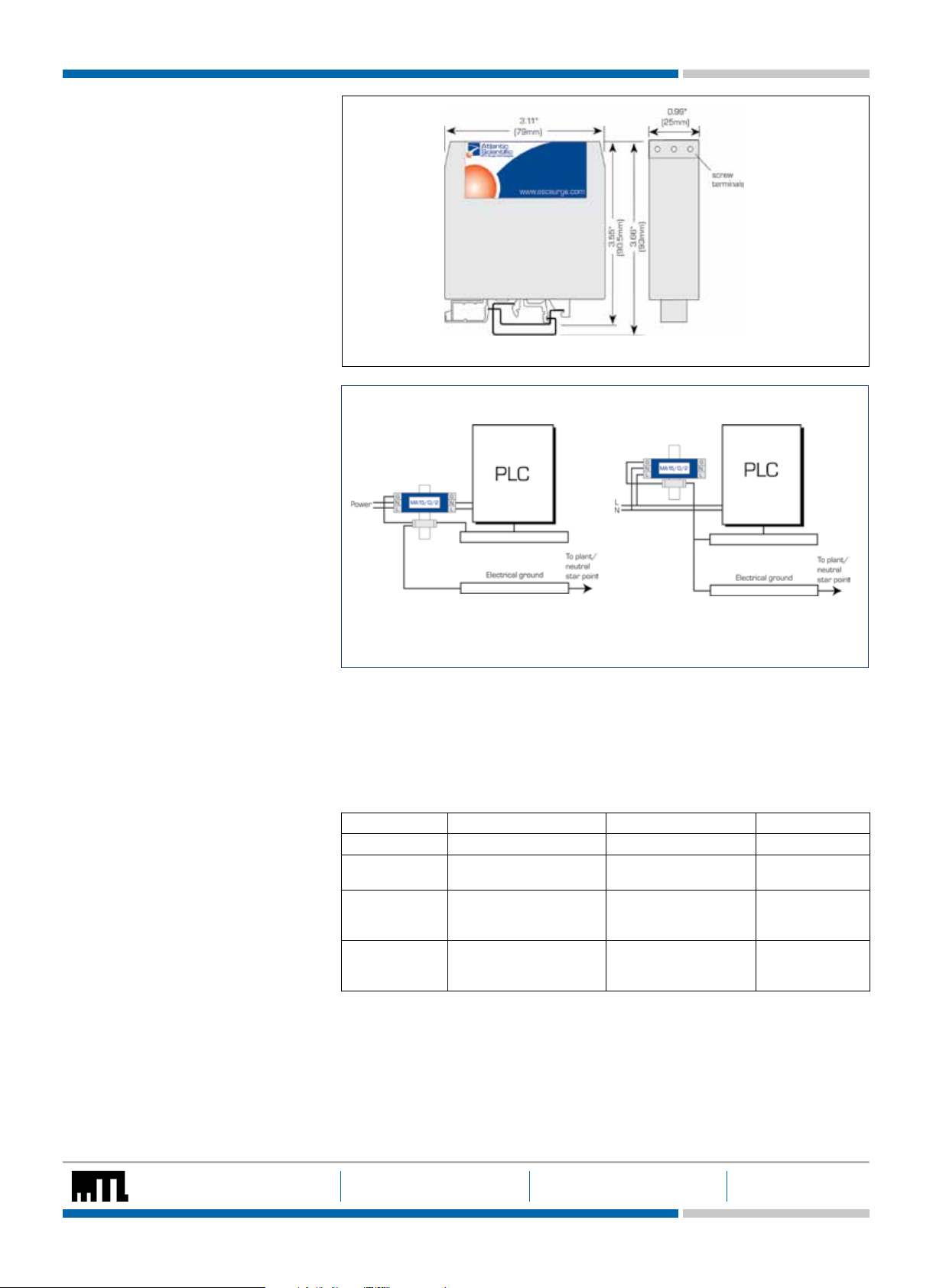
Dimensions
See figure 1
EMC compliance
BS EN 60950 : 1992
BS EN 61000-6-2 : 1999
LED Indication
Green LED on Protection present
Green LED off Internal failure
Installation
Typical wiring connections for MA15 Series
devices are indicated in figure 2. The grounding
of the surge protector and the protected
equipment is very important and, if possible,
should be accomplished as illustrated.
Please note that the unit is marked Line
and Load and it is important that the unit is
installed with the Line side connected to the
incoming power and the Load connected
to the equipment to be protected. For
parallel application however, the Line side is
connected to the incoming power and the
Load left unconnected.
Figure 1 Dimensions
Series Connection
Current <15A
Parallel Connection
Current >15A
Figure 2 Installation
Approvals
Country Standard/Authority Approved for Product
United States
Canada
United States
Canada
India Petroleum & Explosives
NOTE: The above approvals do not apply to the MA15/D/2TT/L and DC applications.
UL 1449
Recognized Component
UL 1449
Recognized Component
UL1604
Safety Organisation
(PESO)
AC Power Product MA15/D/1/SI,
MA15/D/2/SI
Hazardous Locations
Class I, Division 2
MA15/D/1/SI,
MA15/D/2/SI
Groups A, B, C and D
EEx ia MA15/D/1/SI
MA15/D/2/SI
The given data is only in tended as a product des cription and should not b e regarded as a legal warranty o f properties
or guarantee. I n the interest of fu rther tech nical develop ments, we reserve th e right to make design c hanges.
EUROPE (EM EA): +44 (0 )1582 723633 THE AMER ICAS: +1 800 835 7075 ASIA-PACIF IC: +65 6 645 9 888
enquiry@mtl-inst.com csinfo@mtl-inst.com sales.mtlsing@cooperindustries.com 901-108 Rev J 110511
 Loading...