

Page 1
• Protects fax, modems, telemetry and
other telecom equipment
• Robust — 10kA surge capability
• BT or RJ11 style plug and socket
• Full 4-wire protection
• Immune to power crossing
• RFI version available for noisy
environments
technical datasheet
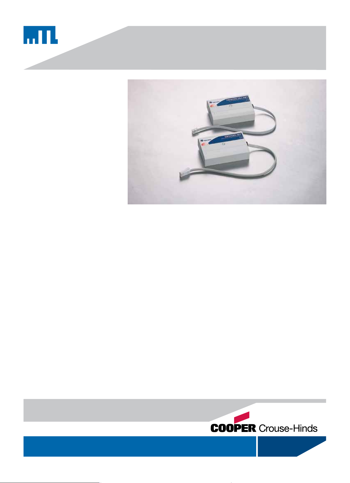
DP200 BT & RJ
Lightning surge protection for modems and telemetry equipment
connected to Public Switched Telephone Networks
The DP200 BT & RJ Series safeguards
modems, telemetry outstations and
fax machines from induced surges and
transient overvoltages caused by lightning
and other electrical disturbances. A single
lightning strike can easily damage or destroy
unprotected equipment and lead to expensive
and disruptive system downtime.
Telecom authorities now encourage the
end user to fit secondary protection for their
equipment. Telecom providers may supply
some simple surge protection such as a gas
discharge tube at the customers’ premises.
However, this is generally only to protect the
telephone line itself and offers little or no
protection for any equipment attached to it.
Hybrid surge protection circuitry is
utilised within the DP200 BT & RJ Series to
provide the best protection devices currently
available. Should mains voltages be applied
to the telecom line, for example by falling
cables, the DP200 BT or RJ unit’s power
crossing immunity prevents damage to both
the telecom equipment and the protection
device.
The DP200/BT/RFI & DP200/RJ/RFI
provide RFI filtering in addition to protection
from lightning induced overvoltages. These
devices suppress interference due to medium
wave radio transmissions, and other sources,
which can compromise normal telecom
operation.
These robust devices, with a 10k A surge
handling cabability, come with either a BT
style plug and socket (DP200/BT and DP200/
BT/RFI) or an RJ11 plug and socket (DP200/
RJ and DP200/RJ/RFI).
These self contained units have been
specifically designed for use on Public
Switched Telecom Networks (PSTN) offering
full 4-wire protection.
DP200 BT & RJ devices are easy to install.
Simply loosen the lid retaining screw, remove
the lid and screw to a wall or panel. The unit
should be earthed with 2.5mm2 cable. This
cable is screwed into the unit’s earth terminal
and the other end is connected to the earth of
the protected equipment.
Complete protection can be achieved
using the MTL range of ac power surge
protection devices to prevent surges entering
equipment via their power supply. The MA05
and MA10 range combines a high level of
protection with the benefit of RFI filtering thus
removing noise and other unwanted signals
from the supply.
901-110 Rev I 160210
www.mtl-inst.com enquiry@mtl-inst.com
Page 2
SPECIFICATION
All figures typical at 77°F (25°C) unless otherwise stated
Maximum discharge current
10kA (8/20µs)
Primary protector rating
10kV (10/700µs)
Leakage current
10µA at working voltage
Working voltage
162V
Max. continuous operating voltage
175V
Ringer Equivalence Number (REN)
0
Ambient temperature limits
-40°F to +158°F - working and storage
(40°C to +70°C) - working and storage
Humidity
5% to 95% RH (non-condensing)
Casing
Plastic ABS - VO IP50 Rated
Weight
4.41 oz (125g) nominal
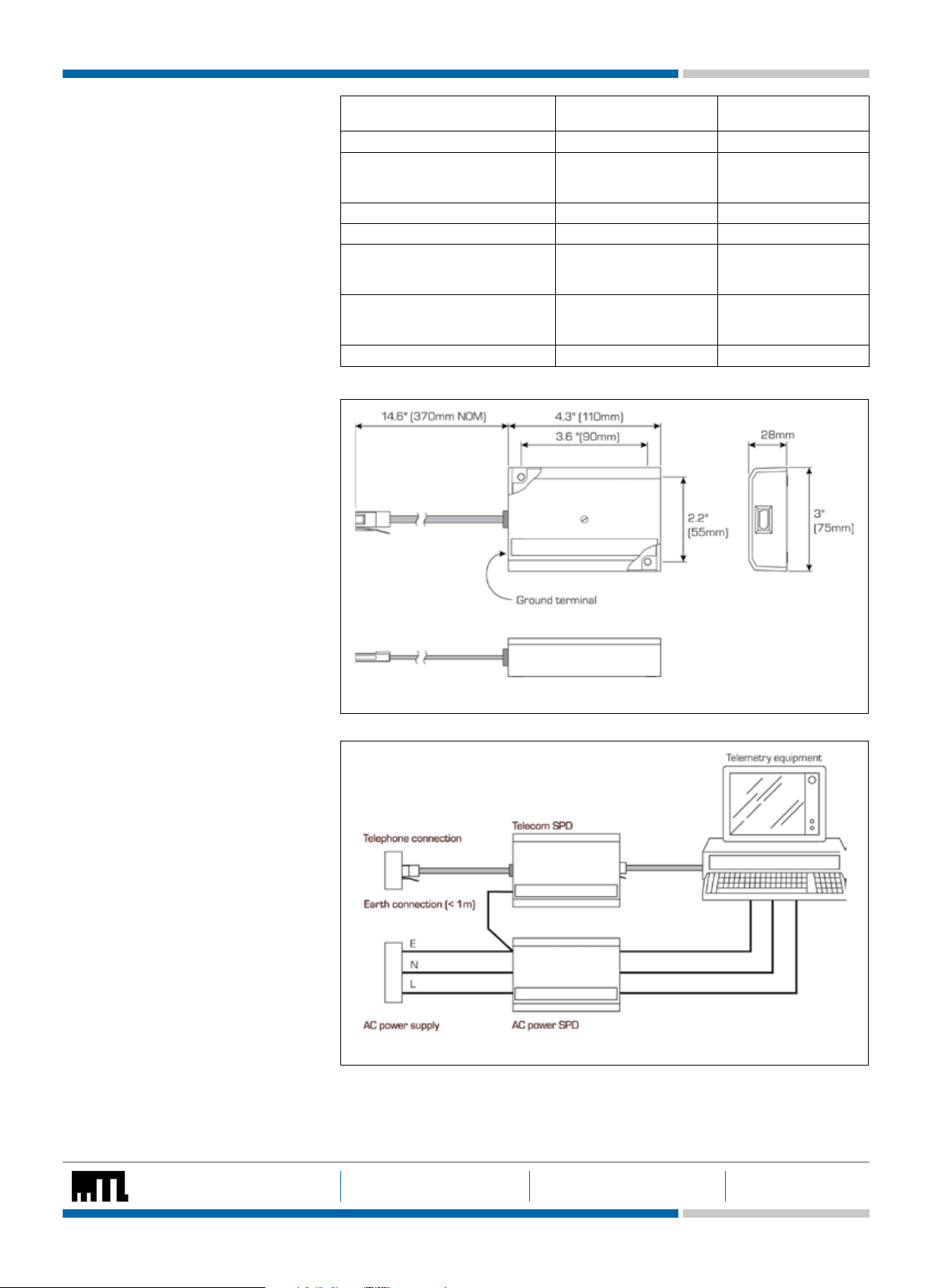
Dimensions
See figure 1
INSTALLATION
In order to mount and ground the unit, the
DP200 BT or RJ must first be opened by
loosening the lid retaining screw and removing
the lid. The unit should be connected to a
good ground point for optimum protection.
This point should be at the power distribution
board if the telecomms cable runs close by,
otherwise at the power supply ground close to
the protected equipment.
Typical values DP200/BT
&DP200/RJ
DP200/BT/RFI
& DP200/RJ/RFI
Line resistance 5 ohms 10 ohms maximum
Limiting voltage
6kV/3kA
5kV/125A
375V
205V
250V
205V
Bandwidth (600 ohms) 6MHz 43kHz
Max stopband attenuation not applicable 65dB
Capacitance
line to line
line to earth
<200pF
<150pF
<1.5nF
<150nF
Insertion loss
@ 300Hz
@3400Hz
0.06dB
0.12dB
0.06dB
0dB
Line balance 300-3400Hz better than 46dB better than 46db
Connection to this ground point should be
made using 14 AWG wire and should be kept
to <1.5 yards. If multiple lines are required, the
grounds should not be ‘daisy-chained’; each
SPD should be grounded separately. Figure 2
shows a complete installation with protection
for both ac power and telecom SPDs fitted.
The ground is taken from the supply to the
telemetry equipment using a short link (<1.5
yards).
The two fixing holes can accommodate either
No.6 or No.8 wood screws or up to 3mm
diameter bolts. The operation of the DP200 BT
or RJ is unaffected by its orientation, although
it should not be mounted on a damp surface.
Once the grounding and mounting operations
are complete, the DP200 BT or RJ is simply
reassembled by fitting the lid back onto the
base and tightening the lid retaining screw. A
comprehensive installation guide is supplied
with each unit.
ORDERING INFORMATION
DP200/BT (BT plug and socket)
DP200/BT/RFI (BT plug and socket
and RFI filtering)
DP200/RJ (RJ11 plug and socket)
DP200/RJ/RFI (RJ11 plug and socket
and RFI filtering)
Figure 1 Dimensions
Figure 2 Installation using both a DP200/BT and an AC power SPD
The given data is only in tended as a product des cription and should not b e regarded as a legal warranty o f properties
or guarantee. I n the interest of further te chnical deve lopments, we rese rve the right to m ake design chan ges.
EUROPE (EM EA): +44 ( 0)1582 723633 THE AMER ICAS: +1 800 835 7075 ASIA-PACIF IC: +65 6 64 5 9888
enquiry@mtl-inst.com csinfo@mtl-inst.com sales.mtlsing@cooperindustries.com 901-110 Rev I 160210
 Loading...