

Page 1

Instruction Manual
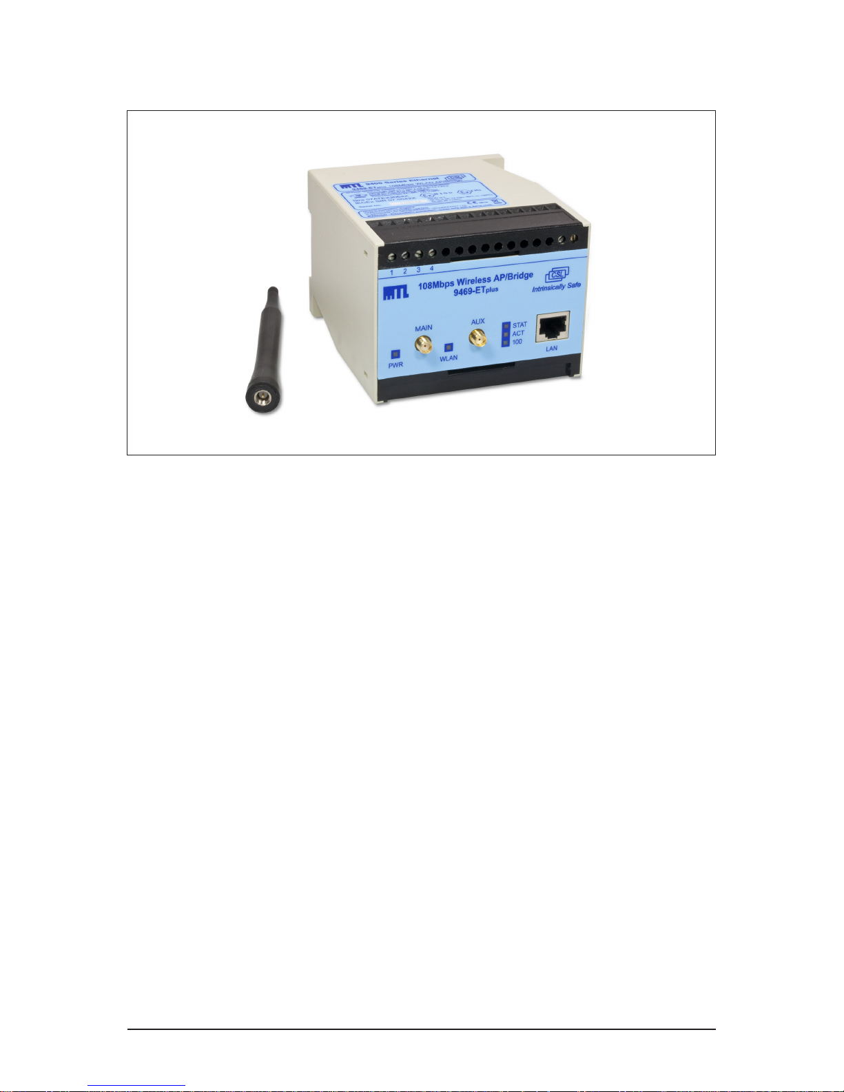
INM9469
9469-ETplus
108Mbps Wireless Bridge/Access Point
Page 2

ii
INM9469-3
June 2012
Page 3

iii
INM9469-3
June 2012
CONTENTS
1 FEATURES ...........................................................1
2 DESCRIPTION ........................................................2
3 INSTALLATION .......................................................2
3.1 Protection ...............................................................2
3.2 Mechanical mounting ......................................................2
3.3 Electrical connections ......................................................3
4 GETTING STARTED ....................................................4
4.1. Select Working mode ......................................................4
4.2. Collect Network Parameters .................................................4
5 LOCATING ON THE NETWORK ...........................................4
6 WEB CONFIGURATION .................................................5
7 SWITCHING BETWEEN ACCESS POINT AND BRIDGE ............................5
8 DEVICE CONFIGURATION ...............................................5
9 UPGRADE ...........................................................5
10 MAINTENANCE & TROUBLESHOOTING .....................................6
11 ENVIRONMENTAL .....................................................6
12 WASTE REMOVAL INFORMATION .........................................6
13 TECHNICAL ..........................................................6
14 ACCESSORIES ........................................................7
15 APPROVALS .........................................................7
16 FM CERTIFICATION INFORMATION ........................................7
17 ATEX & IECEX CERTIFICATION INFORMATION ................................8
© Measurement Technology Limited 2012
Page 4

iv
INM9469-3
June 2012
Page 5
1
INM9469-3
June 2012
1 FEATURES
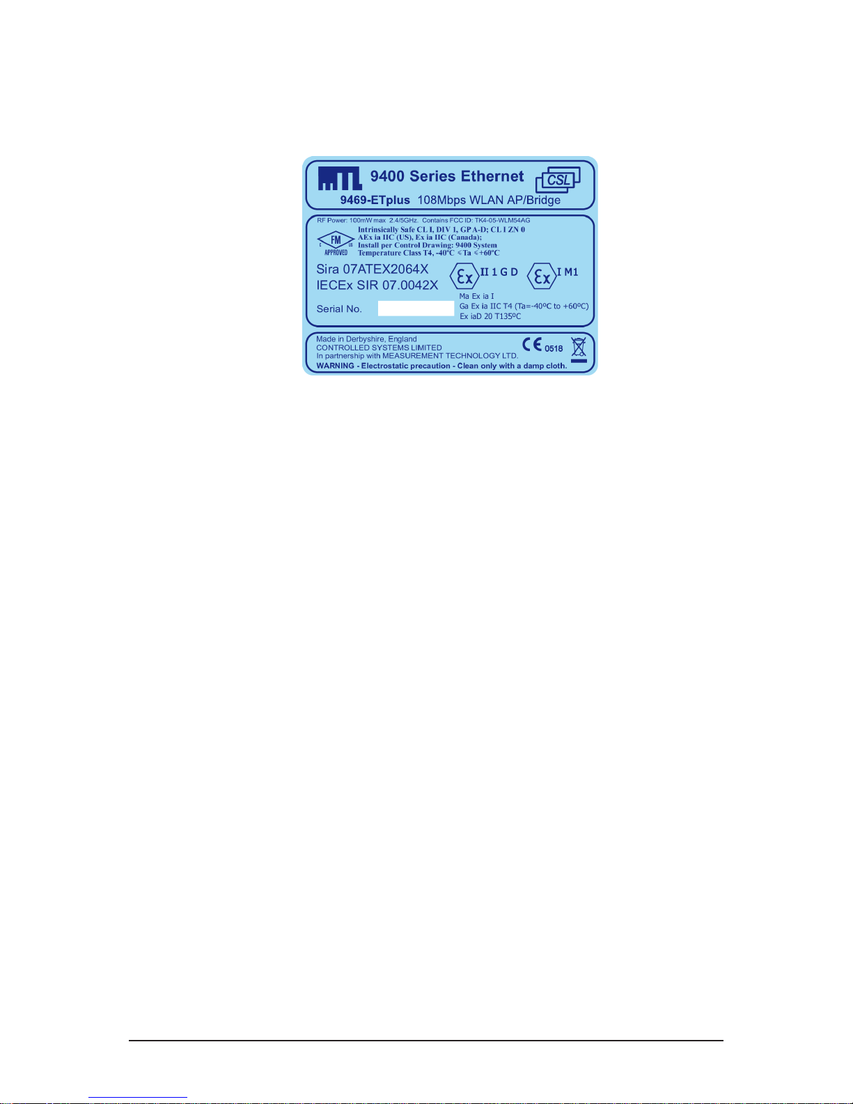
♦ Intrinsically Safe ATEX / IECEx certified / FM / FMC approved
♦ Ga Ex ia IIC T4 GD (surface), Ma Ex ia I M1 (mining)
♦ Zone 1 / Division 1 mounting in a suitable enclosure
♦ Input voltage: 12V dc (10 – 12.8V)
♦ Input current: 270mA
♦ Extended temperature range (–20°C…+60°C)
♦ PoEx™ - “Power over Ethernet” powered device option - accepts module supply via the Cat5e cable*
♦ 10/100Mb Ethernet twisted pair (Cat5e) RJ45 Connection (100m max)
♦ IEEE 802.11 a/b/g/h & Super AG standards, up to 108 Mbps data rate
♦ Security: WEP, WPA-PSK, WPA2-PSK and IEEE 802.1X (RADIUS)
♦ Access Point, Bridge and Wireless Repeater (WDS) Modes of Operation
♦ Easy web based configuration
♦ Status LED’s For:
‘Power On’
WLAN ‘ Activity’
Status/Mode
Copper UTP ‘Activity’
Copper UTP ‘10/100Mb Link’
♦ DIN-rail mounting module
*Note – PoEx is a simple adaptation of the IEEE 802.3af Power over Ethernet (PoE) standard to
bring the benefits to the 9400 Range of Hazardous Area devices. This allows two spare pairs in the
existing Cat5e cable to distribute the power supply from a 9466 Ethernet Switch (Power Sourcing
Equipment – PSE) to each of the devices connected to its five ports (PD – Powered Device). This
adaptation is necessary due to restrictions for Hazardous Area use. It is not implied that the device
conforms to the 802.3af (PoE) standard.
INM9469-3
June 2012
9469-ETplus IS Wireless Access Point/Bridge
Page 6
2
INM9469-3
June 2012
2 DESCRIPTION
The 9469-ETplus 108Mbps Wireless Bridge / Access Point is a dual functionality module. When
used in the Access Point (AP) mode, it allows wireless devices to connect through it onto the wired
Ethernet network, either in Ad-hoc or Infrastructure modes. When used as a Bridge, it makes it
possible to turn any 10/100 Ethernet device into a wireless device, or to connect two network
segments together to make a single network (without the interconnecting wire or fibre optic).
Additionally the module may also be used in its Wireless Repeater (WDS) mode to extend the
range covered by a wireless network.
The Tri-Band operation offers flexibility in situations where the 2.4GHz band may be overcrowded
or where operation in the 5GHz and 5.4GHz bands is desired. The unit supports 802.11d (multicountry roaming) to allow its use globally while complying with regulatory limits.
3 INSTALLATION
WARNING: This equipment must be installed, operated and maintained only be trained competent
personnel and in accordance with all appropriate international, national and local standard codes
of practice and site regulation for intrinsically safe apparatus and in accordance with the instructions
contained here. See also Sections 14, 15 & 16 for approvals and important conditions of safe use.
3.1 Protection
The module requires mounting within an enclosure providing a degree of protection of at least IP6x,
in accordance with EN60529 and in a manner that does not impair the existing creepage and
clearance distances. The enclosure must also comply with the requirements of Clauses 7 and 8 of
EN 60079-0:2006 and be sealed to prevent the ingress of dust.
3.2 Mechanical mounting
3.2.1 DIN rail mounting
The module will ‘snap-fit’ onto standard DIN rail (TS35) to EN 50022. Height off rail - including
connectors but excluding cables = 119mm.
Tilt the module to engage the top DIN rail clips then rotate down and press to the DIN rail until the
lower spring clip is properly engaged.
3.2.2 Flat panel mounting
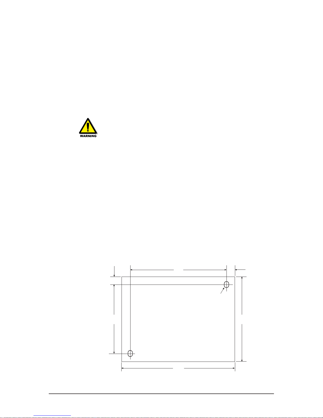
The module has two fixing holes to enable it to be mounted with two M3.5 screws. Use the template
below to establish hole positions. Depth - including connectors but excluding cables = 124mm.
Page 7
3
INM9469-3
June 2012
3.3 Electrical connections
DC power can be supplied to the equipment through the front panel screw terminals or alternatively
using the Power over Ethernet (PoEx) option where DC power is supplied from a 9466-ET module
down the Ethernet Cat5e (or Cat6) cable into the RJ45 connector on the front panel.
WARNING: Whichever wiring method of powering the modules is used, the supply to them must
be derived from a suitably certified, intrinsically safe supply.
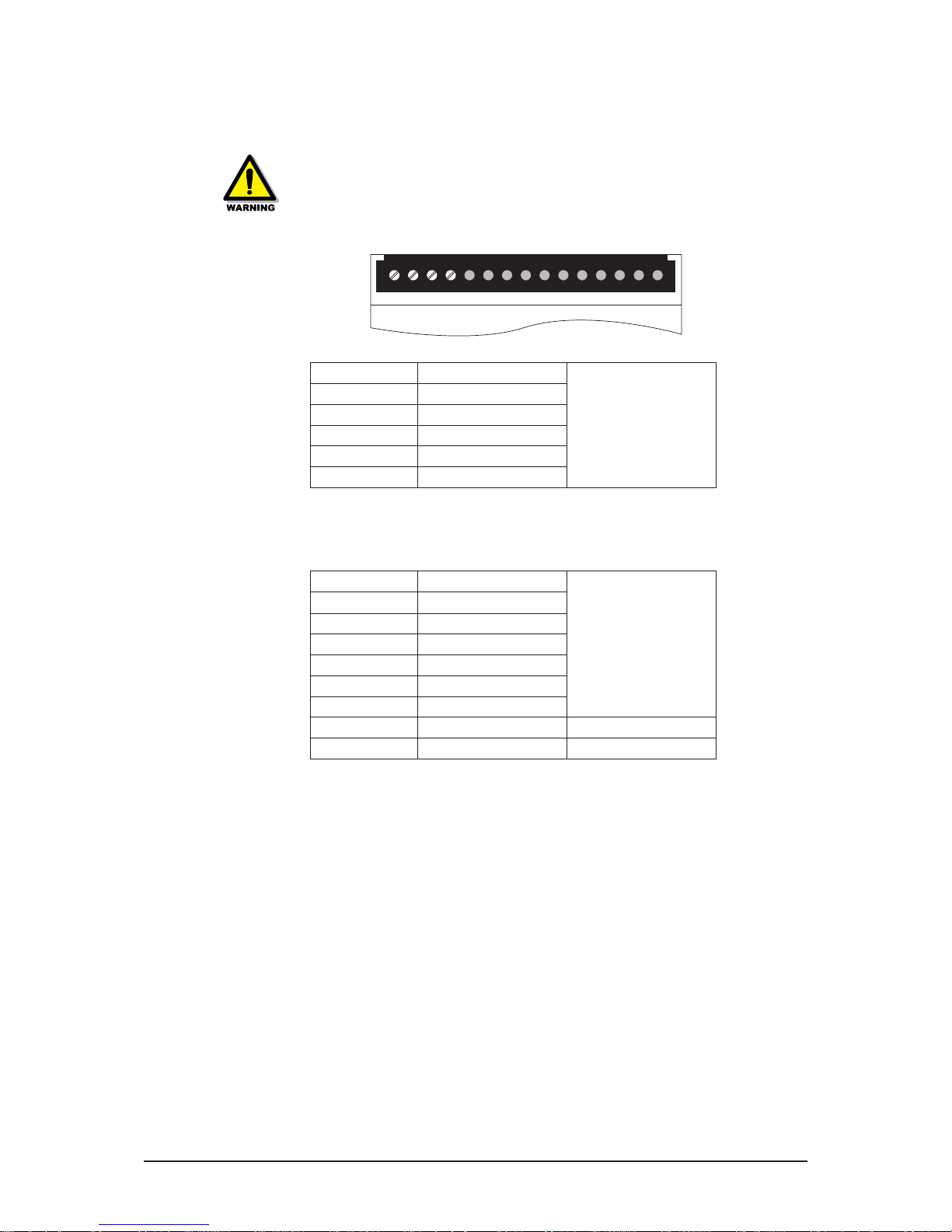
3.3.1 Front Panel Screw Terminals
Terminal No. Function
When using PoEx – no
supply is required on these
terminals.
1
+12V dc in
2
+12V dc in
3
0V
4
0V
5–15
No connection
Note: 1. Terminals 1 & 2 and 3 & 4 are linked internally
3.3.2 Front Panel RJ45 Connectors
10/100 BASE-T Ethernet with TX/RX Crossed MDI-X
Pin No. Function
When using PoEx – no
supply is required on
screw terminals 1 to 4 - see
above.
1 RX +
2 RX –
3 TX +
4 Supply 12V - PoEx
5 Supply 12V - PoEx
6 TX –
7 Supply 0V - PoEx
8 Supply 0V - PoEx
♦ When connecting the Cat5e cable to another device a straight connected RJ45 cable is used,
a crossover cable is not required as the RJ45 connector performs the crossover.
♦ It is recommended that Cat5e cables for Hazardous Area Zone 1 use are ‘Blue’ in colour and
are of good quality (see Accessories section), the Safe Area cables being a colour other than
blue to aid identification.
3.3.3 WiFi - SMA – Antenna Connections
Main Port Antenna 1
Aux Port Antenna 2
Allows the connection of up to two antennae for diversity
The Antenna may be 2.4GHz, 4.9/6GHz or Tri-Band types as required
The antenna should be connected to the SMA socket labelled Main Port. It can be connected
directly or through low-loss 50 ohm co-axial cable, which might be required if the module is housed
in a metal enclosure, or the position of the antenna needs to be optimised.
The Aux Port may be used for a second antennae if diversity is required.
Page 8

4
INM9469-3
June 2012
4 GETTING STARTED
4.1. Select Working mode
The 9469-ETplus creates a link between your Ethernet and a WiFi Network
It can be configured to operate in one of two different modes: Access Point or Bridge, but the default
mode is Access Point
4.1.1. Access Point
In Access Point mode, the 9469-ETplus becomes a communications hub to enable various items of
WiFi equipment (set in “infrastructure” mode) to connect into a wired Ethernet network.
4.1.2. B ri dge
In this mode, the 9469-ETplus gives wired Ethernet output equipment access to a WiFi network. (Use
“infrastructure” mode to connect to an existing access point, otherwise use “adhoc” mode.)
4.2. Collect Network Parameters
In order to configure the 9469-ETplus, you will need to have the following pieces of information.
♦ WiFi Network identifier “SSID”
The SSID is a character string used to identify your WiFi network. To share the same WiFi network,
your device and the other WiFi equipment must use the same SSID. The SSID is up to 32 characters
in length. Uppercase and lowercase letters are considered different.
♦ Radio Channel
You must choose a radio channel in addition to the SSID to define the transmission frequency the
device will use to communicate with other equipment. It is recommended to use less than 3 channels
in the same covered area in order to avoid disturbances. It is also recommended to leave at least
two unused channels between each radio channel. In Ad-hoc mode, all the equipment must have
the same radio channel. Legislation is different in each country; check what channels you can use
in the country where the device is installed.
♦ Device IP Address
If you don’t use DHCP, you must define an IP address for the device. To assign an IP address, contact
the network administrator.
♦ LAN Subnet Mask
You must configure a subnet mask for the device. Refer to the subnet mast of your local network.
Consult the network administrator if in doubt.
♦ Gateway Address (if required)
♦ WEP or WPA Security keys
5 LOCATING ON THE NETWORK
In order to locate the device on the network, use the locator program supplied. This is a simple
standalone application that does not require installation, just copy the file to your hard drive
Connect the device to the network and run the locator.exe program.
The locator program offers the following functions
♦ Scan
When you click this button locator looks for the device on the network.
♦ Configure
When you click this, you can configure the IP Address or enable DHCP.
♦ Upgrade
This button is not implemented within the 9469-ETplus.
♦ Web
Clicking this launches the Administrator web page of the device is brought up.
Page 9
5
INM9469-3
June 2012
Note. If the device is behind a gateway the locator program will not find it. Use a computer on the
same local network as the device for initial setup.
If a firewall is installed on the computer ensure that UDP port 17784 is not blocked
6 WEB CONFIGURATION
To configure the device, run the administration web page. There are two ways to do this
♦ Run your web browser and, if known, enter the IP address in the address field.
(Note: the default IP address is 192.168.1.253)
♦ Locate the device using the locator program mentioned in Section 5, then click on the Web button.
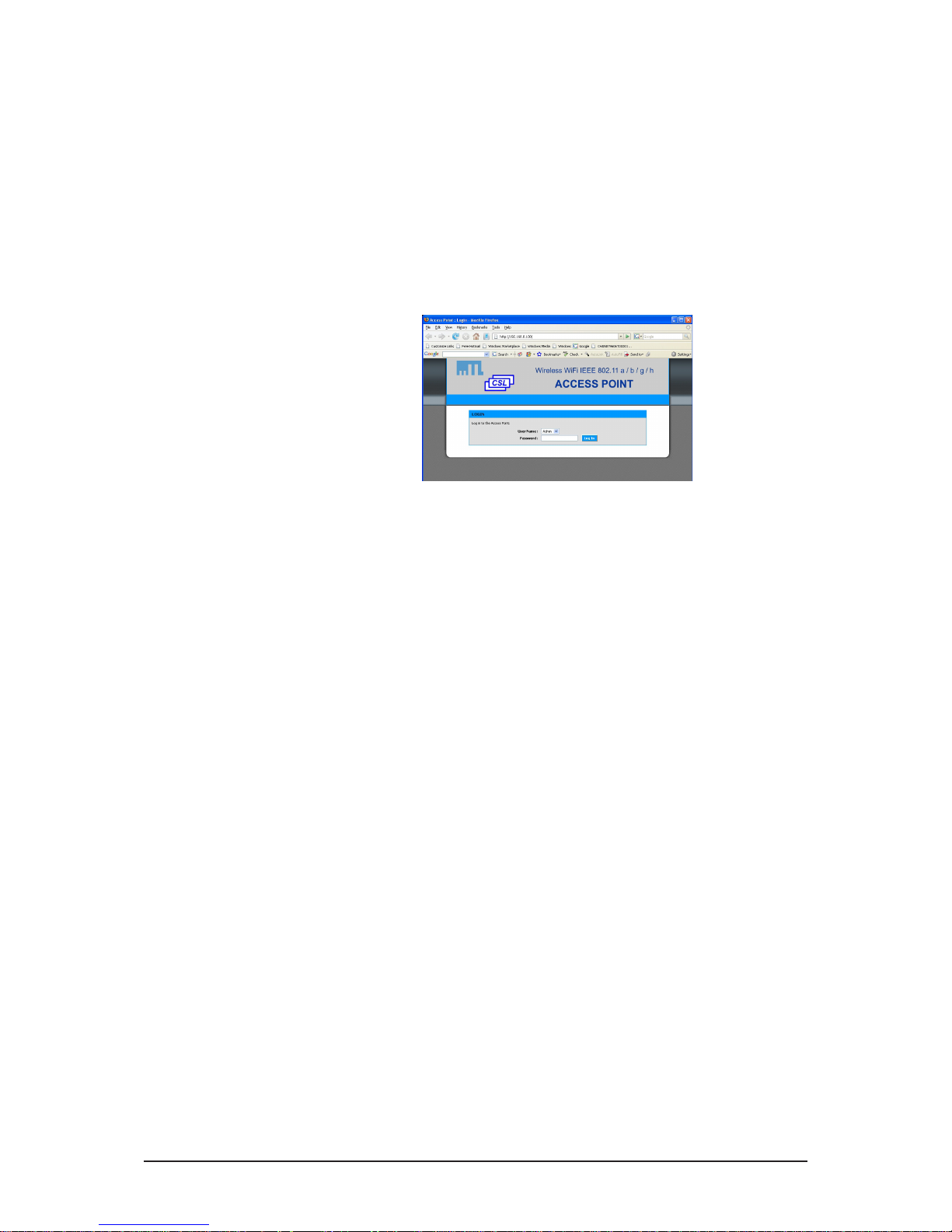
Once on the Web pages a screen appears as below. Initially there is no password.
7 SWITCHING BETWEEN ACCESS POINT AND BRIDGE
To change the operating mode, enter the menu BASIC->WIRELESS and choose the firmware you
want to use. Then click on Save Settings and Reboot the Device. The device will then restart and
use the selected firmware.
8 DEVICE CONFIGURATION
The administration pages consist of the following five categories
♦ Basic
Configure IP addresses, 802.11 mode, radio channel, SSID, security.
♦ Advanced
Configure MAC address filtering
♦ Tools
Set User password, admin password, view firmware version, upgrade firmware
♦ Status
Device info, IP addresses, Radio Channel, Connected devices.
♦ Help
Comprehensive help on all the parameters
9 UPGRADE
In order to upgrade the device follow the steps below
♦ Open the administration web page
♦ Click on tools -> Firmware
In the firmware upgrade section browse to select the new firmware file
♦ Click on Upload
♦ If the upgrade is successful the device will restart
Page 10

6
INM9469-3
June 2012
10 MAINTENANCE & TROUBLESHOOTING
The module is provided with LED indicators to assist in recognising possible fault conditions.
Refer to the following table for assistance in interpreting LED activity.
OFF FLASH ON
PWR
(green)
Power fail N/A Power OK
WLAN
(yellow)
Idle
Wireless LAN
data activity
N/A
STAT
(red)
AP mode = Normal
status
–
Fault
Bridge mode =
connection to AP is
established
Bridge mode =
attempting to
connect to AP
ACT
(yellow)
Ethernet link
disconnected
Ethernet link
activity
Ethernet link
connected
100
(green)
Ethernet link set to
10M bps
N/A
Ethernet link is
100 Mb ps
11 ENVIRONMENTAL
Operating Temperature –20°C…+60°C
Storage Temperature –20°C…+60°C
Humidity 5…95% RH, non condensing
12 WASTE REMOVAL INFORMATION
The electronic equipment within must not be treated as general waste. By ensuring
that this product is disposed of correctly you will be helping to prevent potentially
negative consequences for the environment and human health, which could otherwise
be caused by incorrect waste handling of this product.
For more detailed information about the take-back and recycling contact MTL.
13 TECHNICAL
Ethernet LAN
RJ45 10/100 Base TX Interface
WiFi
IEEE 802.11a/b/g/h 2.4 / 5 / 5.4 GHz standards, multi-country Roaming support (IEEE
802.11d). Dynamic Frequency Selection (DFS) support provides flexible selection of best frequency
to allow mobility among all existing IEEE 802.11a/b/g/h networks; “ClearVoice” band provides
non-overlapping channels for fast-speed data transmission; Transmission Power Control (TPC) offers
flexibility to adjust RF output power.
Data Rate
Up to 108Mbps (Super AG mode)
Channels
13 channels (b/g modes), 8 channels (a mode), 11 channels (h mode)
Output Power
Transmitter +20dBm (TPC)
Sensitivity
Receiver –92dBm for IEEE 802.11a/g and –95dBm for IEEE 802.11b
Modulation
OFDM: BPSK, QPSK, 16QAM, 64QAM DSSS: DBPSK, DQPSK, CCK
Page 11

7
INM9469-3
June 2012
Security
64/128 bits WEP, WPA-PSK, WPA2-PSK, IEEE 802.11x (RADIUS) authentication, MAC address
filtering, SSID broadcast control.
Modes
Access Point (AP) for WiFi Network Infrastructure, Bridge mode to connect any 10/100 wired
Ethernet equipment to a wireless network, Repeater (WDS) mode to extend wireless coverage,
Infrastructure & AD-HOC modes are supported.
Administration
Built-in Web interface. Setup of the device using a web browser.
14 ACCESSORIES
For interconnecting the 9460-ET range of products, we offer approved RJ45 Cat5e UTP cables in
various standard lengths (0.5…100m).
The ANTSMA94 omnidirectional antenna is ideal for use where good general coverage is required.
Ordering details
Copper Twisted Pair UTP Patch Cable (Blue) pre-terminated RJ45-RJ45 connectors
Part No. CSL9405-xx ( -xx is used to signify the length of the cable.)
Part No. ANTSMA94 Omnidirectional antenna
15 APPROVALS
The operating parameters must not exceed those as detailed on the certificate.
♦ 2004/108/EC EMC Directive
♦ 2006/95/EC Low Voltage Directive
Region Europe (ATEX) International IECEx USA Canada
Authority SIRA SIRA FM FMC
Standard EN 60079-0: 2006,
EN 60079-11: 2007,
IEC 60079-26: 2006,
EN 50303: 2000,
IEC 61241-0: 2004,
IEC 61241-11: 2005
IEC 60079-0: 2004,
IEC 60079-11: 2006,
IEC 61241-0: 2004,
IEC 61241-1: 2005
36 00 : 1998
3610: 2007
3810 : 20 05
C22.2 No. 61010.1: 2004
C22.2 No. 157: 1992
CAN/CSA-E60079-0:
2007
CAN/CSA-E60079-11:
2002
Approved forE I M1
E
II 1GD
Ma Ex ia I
Ga Ex ia IIC T4
Ex iaD 20 T135°C
(Ta = –40˚C to +60˚C)*
Ma Ex ia I
Ga Ex ia IIC T4
Ex iaD 20 T135°C
(Ta = –40˚C to
+60˚C)§
IS/I/1/ABCD/T4 Ta=60°C
I/0/AEx ia IIC T4
Ta=60°C
IS/I/1/ABCD/T4 Ta=60°C
I/0/Ex ia IIC T4 Ta=60°C
Cert. no. Sira 07ATEX2064X IECEx SIR 07.0042X 3034995 3034995C
* (see specification for operating temperature range)
16 FM CERTIFICATION INFORMATION
Special Condition of Use - Factory Mutual (USA & Canada)
♦ The Model 9469-ETplus shall be installed in compliance with the enclosure, mounting, spacing
and segregation requirements of the ultimate application.
♦ The Model 9469-ETplus shall be excluded from use in environments containing chemical
vapours of the Ketone or Ester families.
Page 12

8
INM9469-3
June 2012
17 ATEX & IECEX CERTIFICATION INFORMATION
The following information is in accordance with the Essential Health and Safety Requirements
(Annex II) of the EU Directive 94/9/EC [the ATEX Directive - safety of apparatus] and is provided
for those locations where the ATEX Directive is applicable.
General
a) This equipment must only be installed, operated and maintained by competent personnel.
Such personnel shall have undergone training, which included instruction on the various types
of protection and installation practices, the relevant rules and regulations, and on the general
principles of area classification. Appropriate refresher training shall be given on a regular
basis. [See clause 4.2 of EN 60079-17].
b) This equipment has been designed to provide protection against all the relevant additional
hazards referred to in Annex II of the directive, such as those in clause 1.2.7.
c) This equipment has been designed to meet the requirements of intrinsically safe electrical
apparatus in accordance with EN 60079-0, EN 60079-11 and EN 60079-26.
Installation
a) reference to the IEC code of practice IEC 60079-14. In addition, particular industries or end
users may have specific requirements relating to the safety of their installations and these
requirements should also be met. For the majority of installations the Directive 1999/92/EC
[the ATEX Directive - safety of installations] is also applicable.
b) Unless already protected by design, this equipment must be protected by a suitable enclosure
against:
i) mechanical and thermal stresses in excess of those noted in the certification documentation
and the product specification.
ii) aggressive substances, excessive dust, moisture and other contaminants.
c) This equipment is intrinsically safe electrical apparatus and is normally mounted in a
hazardous area. When mounted in a Zone1 location the apparatus must be provided
with an enclosure, which offers an additional degree of protection appropriate to the area
classification.
Read also the Special Conditions for Safe Use for any additional or more specific information.
Special Conditions for Safe Use
1. When used with Group I gases, the Modules shall each be mounted within an enclosure
providing a degree of protection of at least IP54, in accordance with EN 60529, and in a
manner that does not impair the existing creepage and clearance distances. The enclosure shall
also comply with the requirements of Clauses 7 and 8 of EN 60079-0:2006.
2. The connectors do not meet the ingress protection rating of IP20, therefore, this shall be taken
into consideration during the installation of the 9400 Series Ethernet Modules when used with
Group II gases, and each module shall be provided with an enclosure that is commensurate
with the environment into which it is installed.
3. The supply to the modules must be derived from a suitably certified, intrinsically safe supply.
Inspection and maintenance
a) Inspection and maintenance should be carried out in accordance with European, national
and local regulations which may refer to the IEC standard IEC 60079-17. In addition specific
industries or end users may have specific requirements which should also be met.
b) Access to the internal circuitry must not be made during operation.
Repair
This product cannot be repaired by the user and must be replaced with an equivalent certified
product.
Marking
Each device is marked in accordance with the Directive and CE marked with the Notified Body
Identification Number.
This information applies to products manufactured during or after the year 2012.
Page 13
9
INM9469-3
June 2012
Page 14
latigid
DRAWN : IAC
DATE: 05/12/2009
CONTROLLED SYSTEMS LTD.
SWADLINCOTE, DERBYSHIRE. ENGLAND
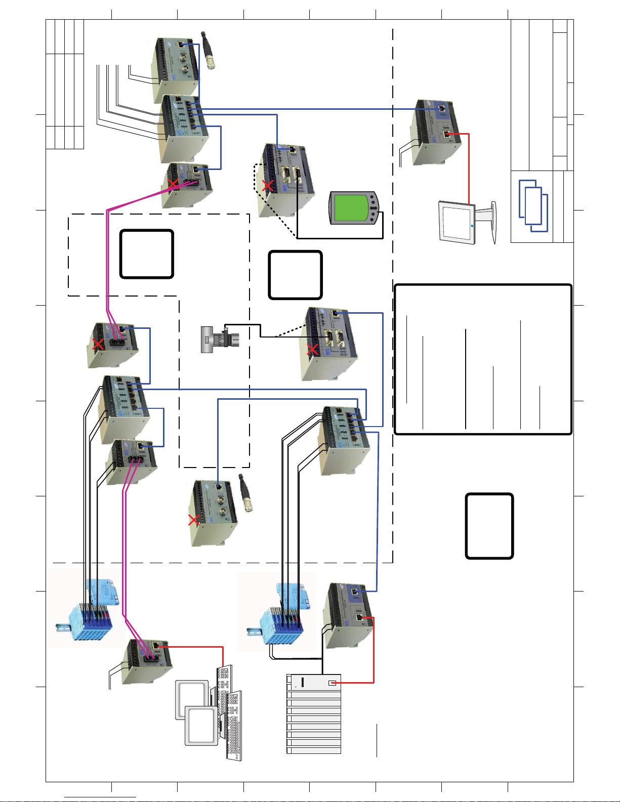
9400 Seri es Ethernet
System Drawing of
Typical Installation
SIZE DWG NO REV
A3 9400 System 4
SCALE SHEET
1OF 2
CSL
SCALE
TITLE
H
G
F
E
D
C
B
A
87654321
H
G
F
E
D
C
B
A
87654321
20/08/2009
DATE
28/03/2007
REV DESCRIPTION
Updated f or Issue2
Changes required for FM3
05/12/2009Added shee t 24
Fibre-Optic
Cable
Fibre-Optic
Cable
Cat5e/Cat6
I.S. Cable
Cat5e/Cat6
I.S. Cable
9465
Media
Converter
9466 5x Port
Switch
9461
Serial
Gateway
Unspecified Safe Area
Equipment
Unspecified Safe Area
Equipment
9468
Ethernet
Isolator
9468
Ethernet
Isolator
9461
Serial
Gateway
9466 5x Port
Switch
9465
Media
Converter
9465
Media
Converter
9466 5x Port
Switch
Certified or
Safe Area
Media
Converter
ZONE 1
Class I
Div 1
SAFE AREA
ZONE 0
Class I
Div 1
Unspecified Zone 0 Div 1
Equipment Entity
Parameters Matching
9461 - RS232/TTL.
RS485/422 Port
Unspecified Zone 1
Div 1 Equipment
Entity Parameters
Matching 9461 -
RS232/TTL. RS485/
422 Port
Power Supply Connections
12Vdc IS Power Supply (psu)
Any suitably certified IS power supply unit
for the intended gas/dust group and satisfying
the following requirements
Uo = 15.4V maximum (12.8V for 9469 module)
9461, 9465, 9466 Modules (app)
Ui = 15.4V
Ci=Li=0
9469 Modules (app)
Ui = 12.8V
Ci=Li=0
9468 Modules 24Vdc Supply Input
Um = 253Vac
Supply Cable
Cc (cable) <= Co (psu) - Ci (app)
Lc (cable) <= Lo (psu) - Li (app)
L/R(cable) <= Lo/Ro (psu)
12VDC
IS Power
Supply
9469 WLAN
AP/Bridge
PoEx Supply for Port 3 Device
Supply for 94 66
PoEx for 9461
via Port 3
Supply for 9466
PoEx for 9465
via Port 5
Supply for 9465
(PoEx not used)
Supply for 9466
PoEx Supply for Po rt 5 Device
Supply for 9469
PoEx Supply for Port 1 Device
PoEx Supply for Port 3 Device
No PoEx
No PoEx
PoEx for 9465
via Port 1
No PoEx
No PoEx
PoEx for 9461
via Port 3
NO
POWER
NO
POWER
NO
POWER
NO
POWER
No PoEx
NO
POWER
PoEx Supply for Port 5 Device
PoEx for 9469
via Port 5
9469 WLAN
AP/Bridge
1. For ease of identification -Use BLUE coloured
Cat5e/6 cables in Zone 1 and 0 Hazardous
Areas, any other colour for Zone 2 or Safe Area
NOTES
2. 9465 Optical Radiation <= 5mW
9469 Radio Frequency Radiation <= 500mW
3. Fibre-Optic and BLUE I.S. Cat5e cables may run in
Zone 0, 1, 2 and Safe Area
4. 9400 Series Modules may be mounted in Zones 1, 2
or Safe Area (9468 may only be mounted in Safe Area)
5. 9400 Series Modules must be installed in a suitable
manner for the surrounding conditions, this may require
an additional protective enclosure in some areas.
6. PoEx (Power over Ethernet for Hazardous Areas) A
means of distributing IS power supplies to devices via
the Cat5 Ethernet cable as an alternative to a separate
power cable. Ensure only one power source is used
(PoEx or separate power cable)
7. Refer to User Manual for Connections and Installation
Instructi ons. See Certificat e for Safety Description
12VDC
IS Power
Supply
12VDC IS
Power Supplies
24Vdc
Um = 253Vac
Um = 253Vac
Um = 253Vac
24Vdc
Um = 253Vac
Page 15
DRAWN : IAC
DATE: 05/12/2009
CONTROLLED SYSTEMS LTD.
SWADLINCOTE, DERBYSHIRE. ENGLAND
9400 Seri es Ethernet
System Drawing of
Typical Installation
SIZE DWG NO REV
A3 9400 System 4
SCALE SHEET
2OF 2
CSL
SCALE
TITLE
H
G
F
E
D
C
B
A
87654321
H
G
F
E
D
C
B
A
87654321
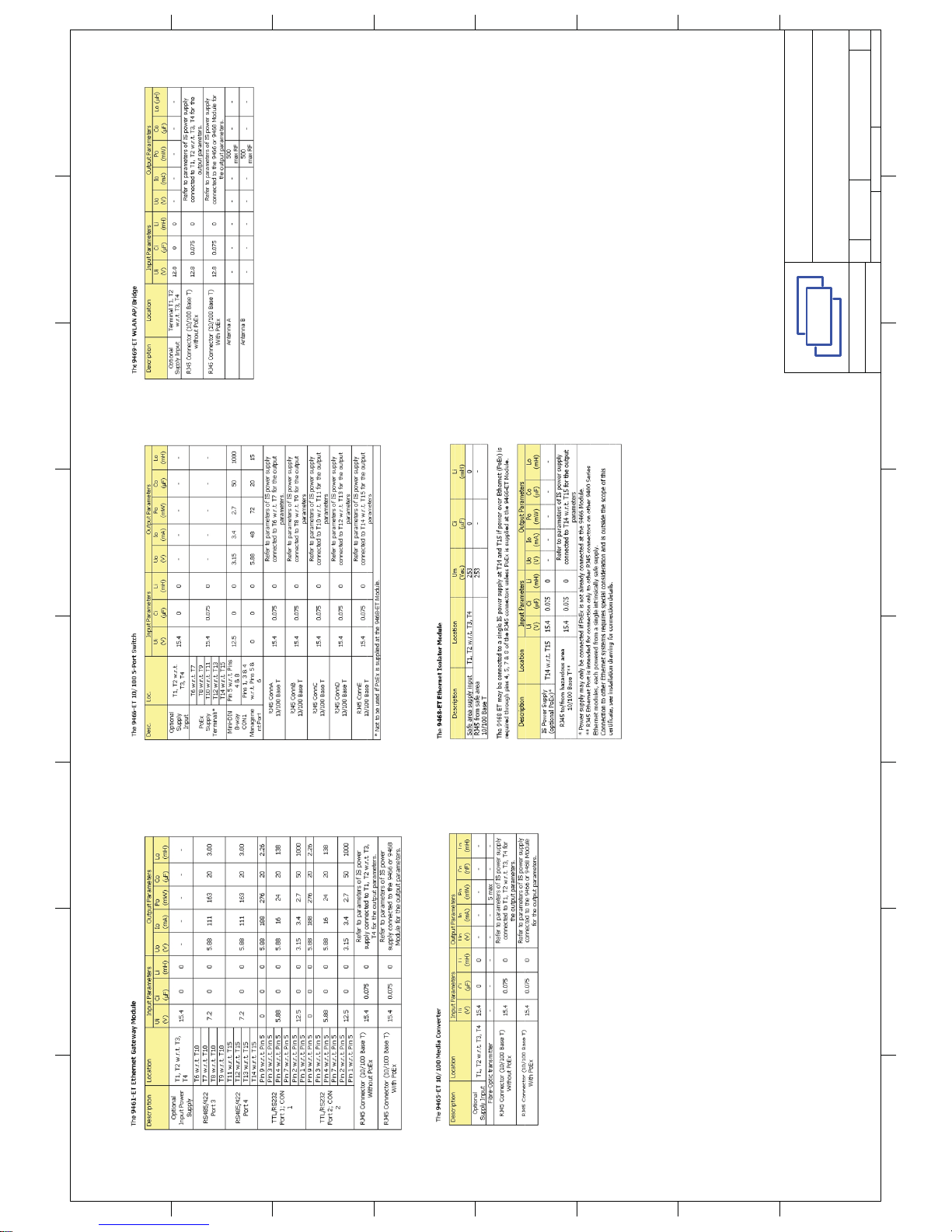
NOTE: RJ45 ETHERNET PORTS* ARE INTENDED FOR
CONNECTION ONLY TO OTHER 9400 SERIES MODULES
SHOWN ON THIS DRAWING.
*(With the exception of 9468-ET Safe Area port)
Page 16

Group Internet home page http://www.mtl-inst.com/
Members of The MTL Instruments Group
MTL Instruments Pty Limited
9 /12 Billabong Street
Stafford
Queensland 4053
Australia
Tel: + 61 1300 308 374 Fax: + 61 1300 308 463
E-mail: [email protected]
Cooper Electric (Shanghai) Co. Ltd.
Room 2001, China Life Tower
16 Chao Yang Men Wai Street
Chao Yang District, Beijing
China 100020
Tel: + 86 10 5980 0288 Fax: + 86 10 8562 5725
E-mail: [email protected]
MTL Instruments sarl
Les Carrés du Parc
10 rue des Rosiéristes
69410 Champagne au Mont d’Or
France
Tel: +33 (0)4 78 64 98 32 Fax: +33 (0)4 78 35 79 41
E-mail: [email protected]
MTL Instruments GmbH
An der Gümpgesbrücke 17
D-41564 Kaarst
Germany
Tel: +49 (0)2131 718930 Fax: +49 (0)2131 7189333
E-mail: [email protected]
MTL India
No. 36, Nehru Street
Off Old Mahabalipuram Road
Sholinganallur
Chennai - 600 119
India
Tel: + 91 (0)44 24501660/24501857 Fax: + 91 (0)44 24501463
E-mail: [email protected]
MTL Italia srl
Via Cantù 11
I - 20092 Cinisello Balsamo MI
Italy
Tel: +39 (0)2 61802011 Fax: +39 (0)2 61294560
E-mail: [email protected]
Cooper Crouse-Hinds Japan KK
MT Building 3F
2-7-5 Shiba Daimon
Minato-ku Tokyo
Japan 105-0012
Tel: +81 (0)3 6430 3128 Fax: +81 (0)3 6430 3129
E-mail: [email protected]
Cooper Crouse-Hinds Korea
12F, Vision Tower
707-2 Yeoksam-dong, Gangnam-gu
Seoul 135-080
South Korea
Tel: +82 2 3484 6795 Fax: +82 2 3484 6778
E-mail: [email protected]
MTL Instruments BV
MTL Instruments BV
Terheijdenseweg 465
4825BK Breda
The Netherlands
Tel: +31(0)76 7505360 Fax: +31(0)76 7505370
E-mail: [email protected]
Cooper Crouse-Hinds Pte Ltd.
No.2 Serangoon North Avenue 5
#06-01 Fu Yu Building
Singapore 554911
Tel: +65 6 645 9888 Fax: +65 6 487 7997
E-mail: [email protected]
MTL Instruments
Villa No. 4, Sector 2-17, Street 6
PO Box 53234,
Abu Dhabi, UAE
Tel: +971 2 446 6840 Fax: +971 2 446 6841
E-mail: [email protected]
Measurement Technology Limited
Great Marlings, Butterfield, Luton, Beds
England LU2 8DL
Tel: +44 (0)1582 723633 Fax: +44 (0)1582 422283
E-mail: [email protected]
Cooper Crouse-Hinds MTL Inc
3413 N. Sam Houston Parkway W.
Suite 210
Houston TX 77086
USA
Tel: +1 281 571 8065 Fax: +1 281 571 8069
E-mail: [email protected]
 Loading...