

Page 1

DCQ-2000
Digital Color
Quad Processor
Operation Manual
15/02/2002
Page 2

Index
Features .................................................3
Introduction........................................... 4
Important Safeguards .......................... 5
Front Panel Controls ............................ 6
Rear Panel Connectors ........................ 6
Installation ............................................ 7
Connections
Typical ........................................ 8
Live Zoom Mode ........................ 8
Operating Procedure
Quad Mode ................................ 9
Single Camera Mode ................ 9
Sequential Mode ....................... 9
VCR Playback Mode ................. 9
2x Zooming and Freezing ........ 9
Live Zoom Mode ....................... 10
Setup Menu
1st Page Menu Screen ............. 11
2nd Page Menu Screen ........... 12
3rd Page Menu Screen ............ 13
4th Page Menu Screen ............. 14
Alarms
Alarm Pin Outs ..........................15
Alarm Mode Operation ............. 16
Alarm Inputs ................... 16
Alarm Control ................. 16
Alarm Output .................. 17
PAL / NTSC ........................................... 17
Specifications ...................................... 18
Warranty Information ........................... 19
Page 3

Features
True Digital Color Video Quad
CCIR-601 Digital Standard NTSC/PAL
True Real Time (60 ips Quad image update rate)
VCR Input and Output with Playback
High Quality Interpolated 2X Zoom
Alarming Inputs per Camera
NO or NC Programmable
Alarm Output Relay
NO & NC Contacts with Common
Audible Buzzer Alarm
99 Alarm Event Log Memory
Independent Picture Controls for each Camera
Brightness
Contrast
Tint
Color
12VDC Power Input
Compact Metal Case
Video Loss Detection
6 Character Camera Title
Time & Date On Screen
Multi Format Date
24 Hr Time Format
Internal Clock backup in case of power outages
Non Volatile Memory for Program Setups
On-Screen Programming
3
Page 4

Introduction
Congratulations on purchasing the DCQ-2000 Digital
Color Quad Processor. This advanced unit accepts composite video signals and coverts them to the Digital CCIR-601
Video standard internally and does all the processing digitally. This allows true real time quad image update rate at 60
Hz for each camera input.
Due to the advanced digital processing, an interpolated 2X zoom mode that finally allows a quality zoom
image to be seen full screen from a VCR playback is possible. Each camera input can individually be adjusted for
brightness, contrast, tint and color to compensate for poor
lighting or poor camera performance.
The On-Screen programming allows for easy user
configuration of the all setups including programming the
Time and Date. Each camera can have an individual title or
label to identify it upon viewing the monitor or playback.
With the built in Time/Date generator the DCQ-2000 can
work with standard VCRs that do not include this feature.
There are separate VCR input and output connectors
so playback can be done through the quad itself. Upon
video loss the DCQ-2000 will sound a buzzer and output an
alarm condition.
The DB-9 connector has hardwire inputs for alarm
contacts for each camera. Upon alarm this camera can go
full screen and the alarm output set to trigger other devices
like your VCR.
This compact 12VDC product can be used in any
battery powered application or mobile enviroment.
The DCQ-2000 will serve all your applications for a
color quad from a basic system to advanced alarming and
playback functions.
4
Page 5

Important Safeguards
1. Read manual thoroughly before setup or operation of this
product.
2. Save this booklet for further reference.
3. Follow the instructions and heed all warning notices
4. Do not use liquid or aerosol cleaners on this product, use
a slightly damp cloth only. Do this only with the unit
unplugged from the power source.
5. Do not use accessories not recommended by your dealer
or installer with this unit.
6. Keep unit in a dry location. Dampness or moisture will be
damage the internal components.
7. Do not block ventilation openings on unit.
8. Never insert any objects into unit, this could result in fire
or electric shock. Never spill any liquid onto or into the
unit.
9. If an outdoor cable is connected to this unit, be sure the
cable is grounded well.
10. For added protection of this unit during a lightning or
electrical storm, or when it is left unused for a long
period of time, unplug it from the wall outlet and
disconnect all cables.
Warning: Cover removal should only be performed by
qualified service personnel. This unit contains no
user serviceable parts.
5
Page 6
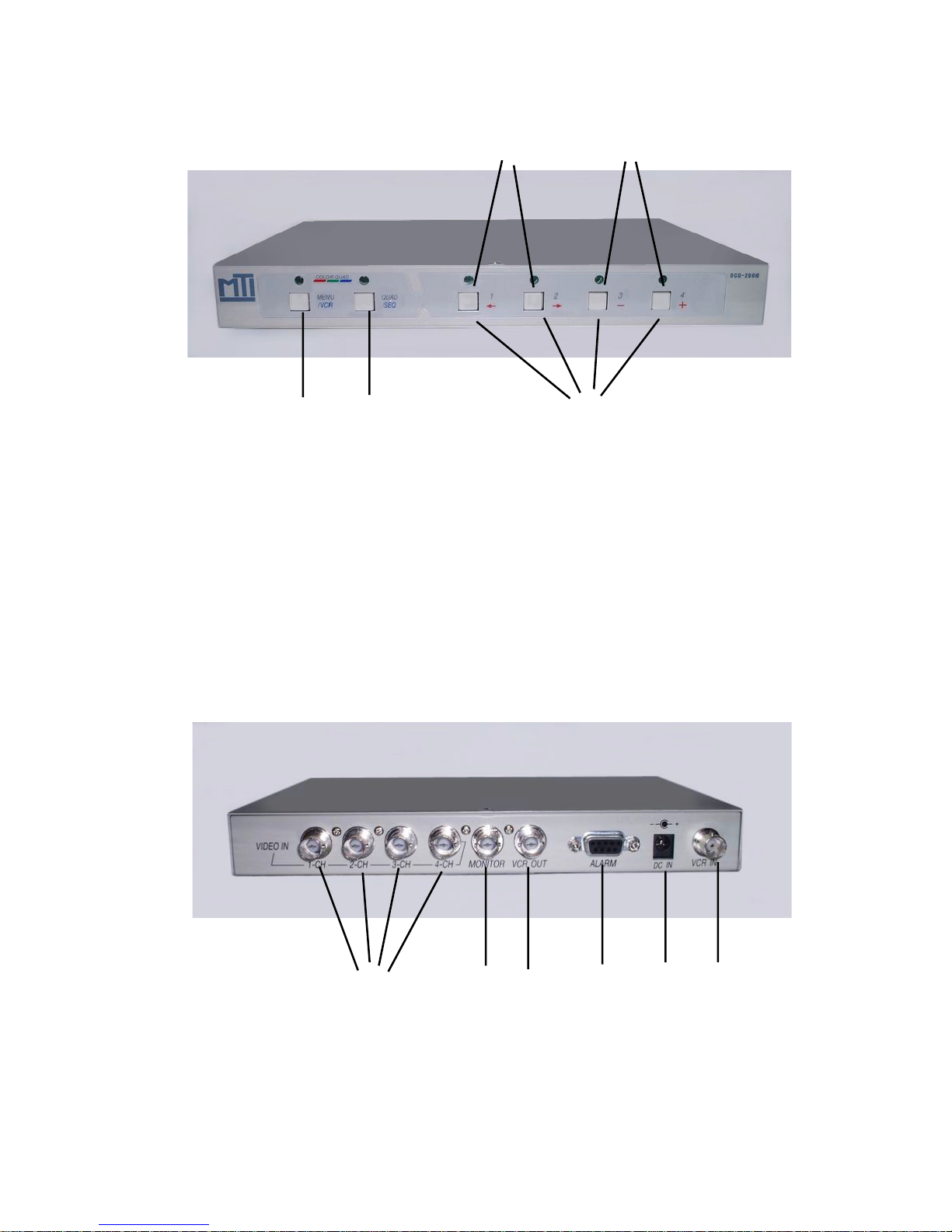
Front Panel
4 5
1 2 3
1 Setup Menu/VCR Mode 4 Select Item (in menu)
2 Quad Mode/Sequential 5 Change Status (in menu)
3 Camera Select
Rear Panel
1 2 3 4 5 6
1 Video In (1-4) 4 Alarm Port
2 Monitor Out 5 Power In (12VDC)
3 VCR Input (Playback In) 6 VCR Output (Record Out)
6
Page 7

Installation
1. Place the unit on a flat, stable surface. Avoid locations that
are subject to direct sunlight, excessive heat, moisture, or
dust.
2. Connect the BNC cables from the cameras to the respective Video In ports. Each camera input is terminated with 75
ohms and require 1 V P-P video signal for proper operation.
3. Connect the Quad “VCR In” to the VCR “VCR Out” connector. Connet the Quad “VCR Out” to the VCR “VCR In” connector.
Note: The Quad “VCR Out” sends the picture to the VCR that
is to be recorded. When the Quad is in the VCR Playback
mode the Quad “VCR In” accepts the output of the VCR to be
playbacked back or zoom on the Quad. However when the
Quad is in this playback mode it does not send the Quad
picture out to the VCR. In other words the Quad is a Simplex
unit, it can either display the Quad image or do Playback from
a VCR but can not do both at the same time.
4. Connect the “Monitor Out” to the Video In of the monitor or
A/V connectors on your TV.
5. Connect the Alarm outputs of other equipment to the respective pins on the DB-9 (Female) connector on the rear of
the unit. Pin Out of this connector is described in Page 12.
6. Connect the Alarm output of the Quad to other equipment
like alarm panel or VCR
7. After you complete all the connections, plug the 12VDC
connector to the unit and plug the adapter to the mains power.
7
Page 8
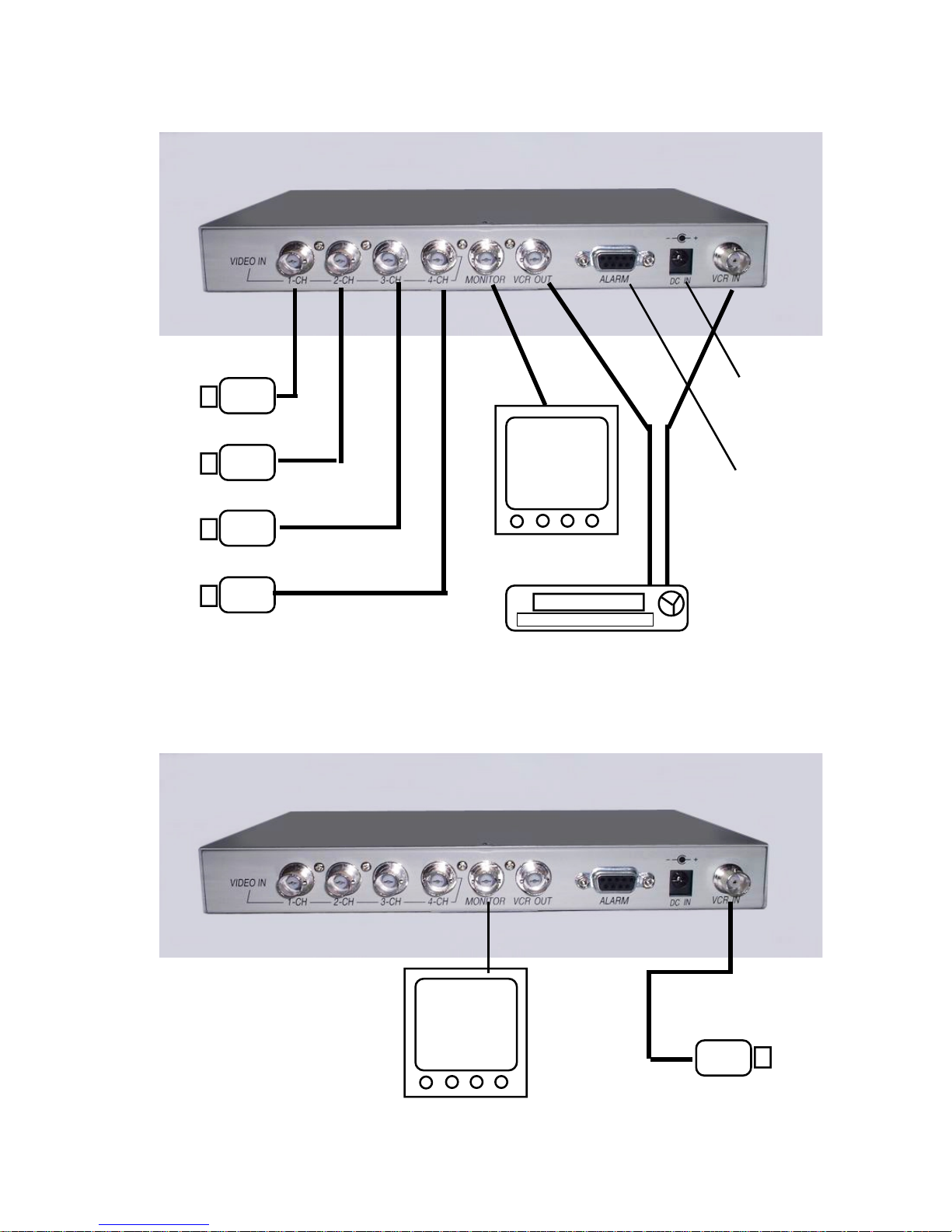
Typical Installation
12VDC
Power
Alarms
Monitor
Live Zoom Mode
8
Color Cameras VCR
Monitor Color Camera
Page 9

Operating Procedure
Upon powering up your quad the unit will sequence between
all the cameras and the quad display automatically. The VCR
will always record the quad image no matter what the picture
is on the monitor display except in the VCR Playback mode.
Quad Mode
Press the “Quad Key” once and the monitor will display only
the Quad image. Press this key again and the full screen
image of the last camera number pressed will be displayed.
Press again and repeat the above.
Single Camera Mode
Press the number of the camera in “Camera Select” key to
see a full screen image of the camera selected.
In this mode, the monitor output port will output the camera
that the user has selected.
Press the “Quad” key again to go back to the quad display.
Sequential Camera Mode
Press the “Seq” key and hold for 1 second to start the automatic camera sequencing. If any camera input has a video
loss or no connection the quad will automatically skip this
camera in the sequencing.
VCR Playback Mode
Press the “VCR” key and hold for 1 second to enter into the
VCR Playback mode. If the VCR is not in playback mode there
will be no display on the monitor. Press the play button on the
VCR and you will see the playback on the monitor.
2X Zooming and Freeze
After you enter the Playback Mode, the user can press one of
the numbers “1” to “4” Camera keys to get into the 2X zoom
9
Page 10

mode to watch one quad picture full screen. The respective
number will zoom the respective quad full screen. Press the
same number key again and this will freeze the zoomed playback picture. Press the same number key again and the
frozen image will be unfrozen. Repeated pressing will alternate between frozen and unfrozen.
Press the Quad key will go back to the full screen playback
picture.
Press the “VCR” key again will exit the VCR Playback Mode.
Note: Make sure you stop the VCR playback to the end of the
recorded section prior to Playback and press the record button
to continue with normal recording.
Live Zoom Mode
The DCQ-2000 can be used for live zoom of any video source.
However when doing this you must connect your live video
source directly to the “VCR Input” on the Quad. Then you will
enter the VCR Playback mode without the VCR being connected. The live image from your camera or other device then
will be displayed. You can then zoom 2x via the camera number keys, this is described on the previous page under Zooming and Freezing.
Remember while in this mode the “VCR Output” will not have
the Quad display and will not be recording while you are in the
“VCR Playback” mode.
10
Page 11
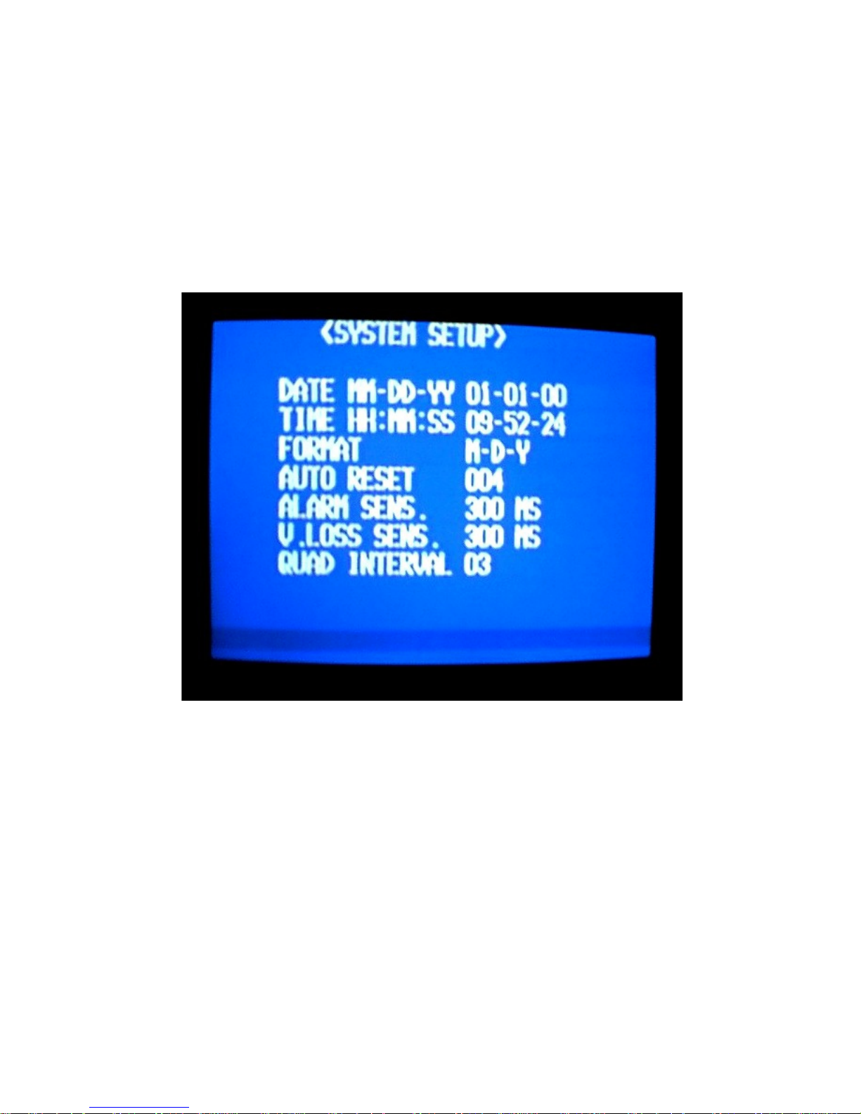
Setup Menu
Press the Menu key to get into the Setup Menu. There are 4
setup pages, press the Menu key repeatedly to change the
menu pages on-screen. Use keys “<“ or “>” to select the item
that you want to change, then use the “+” or the “-” keys to
change the value or status.
1st OSD Menu
Auto Reset: Every time there has been an Alarm or V Loss
event, the DCQ-2000 will trigger an internal timer. When the
timer reaches the value that the user sets, this unit will clear
the event automatically. (Unit:Second)
The user can clear the event by pressing any key.
Alarm Sens: The alarm event will not occur unless the Alarm
trigger is longer than what is set here by the user.
(Unit:millisecond) This is used as a debounce for noisy lines or
11
Page 12
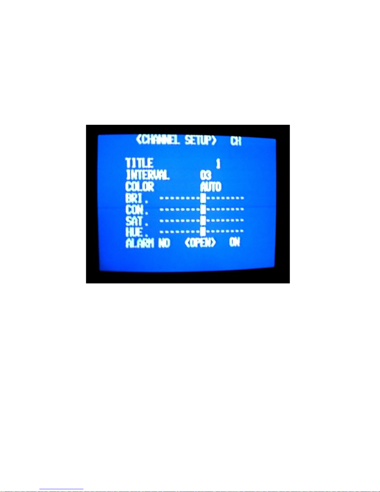
spuratic triggers.
VLoss Sens: The VLoss event will not occur unless the
VLoss trigger is longer than what is set here by the user.
(Unit:millisecond)
Quad Interval: This is the dwell time for display of the Quad
picture while in the sequencing mode. (Unit:second)
2nd OSD Menu
Ch:This selects the input channel or camera number that is to
be programmed.
Title: This is the six character title that can be programmed for
each camera input.
Interval: This is the dwell time for each camera while in the
sequencing mode.
Color: The color killer default is Auto to adjust for color or B/
W cameras. If the video signal of the selected channel is with
12
Page 13
very low chroma level, it must set to “Fix” to disable the
autoremover. This usually happens with a very long cable
connection between the camera and the Quad if no frequency
compensation is used. The limitation of the length will depend
on the specification of the cable.
Bri: This adjusts the brightness of the selected camera.
Con: This adjusts the contrast of the selected camera.
Sat: This adjusts the color saturation or amount of color of the
selected camera.
Hue: This adjusts the hue or tint of the selected camera.
Alarm: There are three parts to this item;
1st selection is to set the type of external alarm equip-
ment. This is NO (Normally Open) or NC (Normally Closed)
types of contacts.
2nd is to select the status detected by this unit in the
power-on initialization. This is either Open or Close.
3rd is to enable or disable the Alarm trigger of this chan-
nel or camera. (On or Off)
3rd OSD Menu
13
Page 14
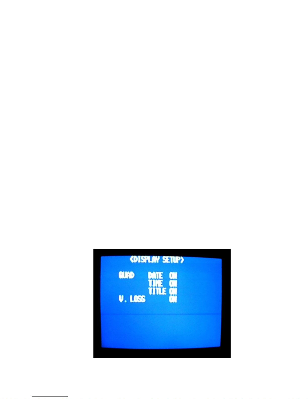
Quad: Enable or disable the on-screen display of the Date,
Time or Title on the “VCR Out” and monitor.
VLoss:Enable or disable the unit to check for video loss for all
cameras.
4th OSD Menu
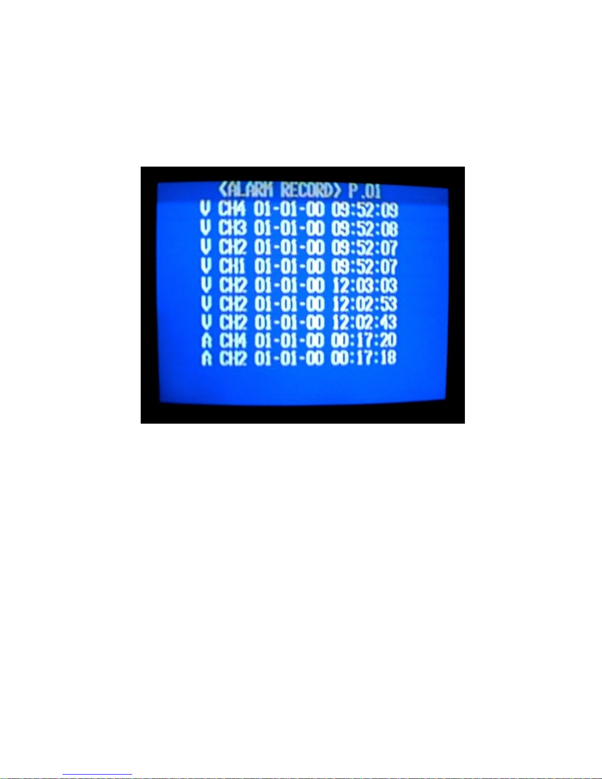
P: The selects the page number of the alarm record event log.
There are 11 pages with 9 records in each page with a total of
99 records maximum in the alarm log.
There are 4 parts to each record:
Alarm or VLoss
Camera Number
Date
Time
14
Page 15

Alarm Port
DB-9 Female (Looking at Rear of Quad)
1. Alarm Out COM
2. Alarm Out NO
3. Alarm Out NC
4. GND
5. Alarm Control
6. Ch1 Alarm Input
7. Ch2 Alarm Input
8. Ch3 Alarm Input
9. Ch4 Alarm Input
Shield - GND
Note: The Alarm input 1 to 4 and clear input are pulled high
internally. Connect the external alarm devices to these
pins.The quad will detect the type of external alarm equipment
automatically in power-on initialization but can be changed in
programming also.
The internal relay was set to NC position normally for the
Alarm output. So pin 1 and 3 will short normally, and will be
opened when an event was occurred.
Pin 2 will be open normally, and will be closed when an alarm
occurs.
Warning: The rating of the internal relay is:
AC 120V @ 1A or DC 30V @ 1A. The user must take care in
not overloading this relay for safety reasons.
15
Page 16

Alarm Mode Operation
Alarm Inputs
When a single alarm input is activated to a true alarm
condition then that camera will become full screen for the
duration of the alarm dwell. If the alarm is still true at the end
of the dwell time, the Quad screen will display for its dwell
period and then repeat the alarm dwell for that camera.
If multiple alarms are activated simultaneously, the the
first alarm dwell will time out with its camera full screen and
then then the Quad screen will appear. Then the second alarm
will display its camera full screen and then the Quad screen.
All the alarm cameras will display in order as above and repeat until all the alarm conditions are cleared.
Alarm Control
The Alarm Control connection to the DB-9 connector can
be used to lock the alarming camera to full screen. After any
alarm input has been activated and that camera is full screen,
connecting the Alarm Control signal to ground will lock that
camera to the homing mode. This will be the only camera you
will see. If another alarm is activated this alarm camera will
home for the dwell time and then go back to the locked home
camera and NOT the Quad mode. The only way to release the
Alarm Control locked camera is to press the “Quad” button to
release this mode.
The Alarm Control signal can be physically connected to
alarm inputs and when the alarm input is connected to ground
(NO only) this camera will automatically be locked in the
homed mode. Remember this locked homed camera can only
be released by pressing the “Quad” key.
16
Page 17
Alarm Output
The alarm output of the DCQ-2000 goes true whenever
there is an internal VLoss alarm or external Alarm Input that
has been true. This Alarm Output stays true for the length of
the alarm dwell that has been programmed by the user. The
alarm output is a Form C contact. There is a NO (Normally
Open), a NC (Normally Closed) and a Common output.
The rating of the internal relay is:
AC 120V/240V @ 1A or DC 30V @ 1A.
PAL / NTSC
The DCQ-2000 is factory configured for the PAL format.
However the DCQ-2000 can operate in the NTSC format.
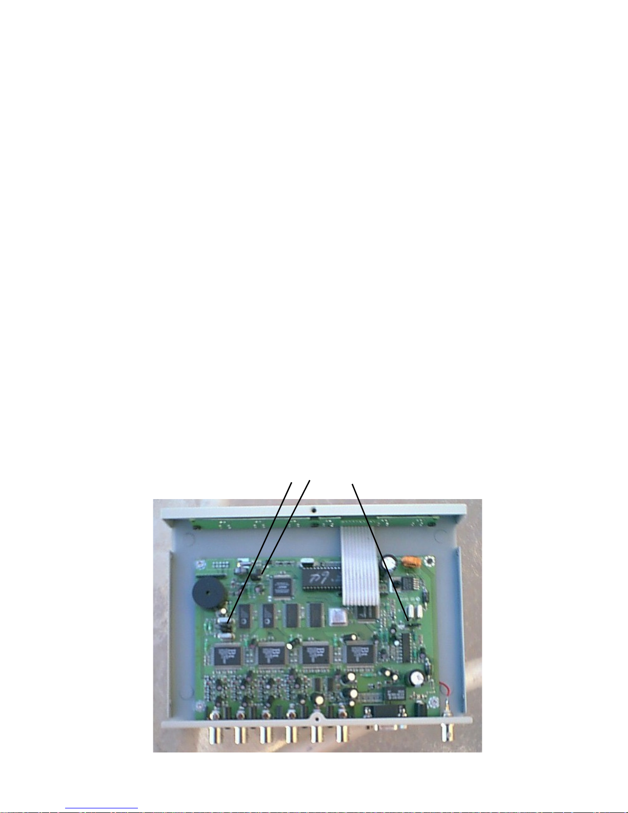
This requires the changing of the internal jumpers only.
Please refer to an AVE approved service technician for
converting the DCQ-2000 to NTSC format. There is a total
for 4 jumpers.
Jumpers
17
Page 18

Specifications
Video Standard CCIR601 NTSC/PAL
Sampling Rate 910 x 525 pixels per line for NTSC
1135 x 625 pixels per line for PAL
Total Display Pixels 858 x 512 pixels for NTSC
864 x 576 pixels for PAL
Display Rate 60 fps NTSC
50 fps PAL
Quad Update Rate 60 fps NTSC
50 fps PAL
Camera Inputs (BNC) Composite Video 1 V P-P
75 ohm terminated
VCR Input (BNC) Composite Video 1 V P-P
75 ohm terminated
VCR Output (BNC) Composite Video 1 V P-P
into 75 ohm terminated load
Monitor Output (BNC) Composite Video 1 V P-P
into 75 ohm terminated load
Alarm Input (DB-9 F) Hi-Z Impedance, NO or NC
programmable. 1 per camera
Alarm Output (DB-9 F) Relay Form C Contact
NO / NC / Common
AC 120V @ 1A
DC 30V @ 1A
Operation Temperature 5 degrees to 45 degrees Celsius
Relative Humdity 5% to 85% Non-Condensing
Weight 1 lb. 14.5 oz
Size 8 5/8”D x 6 1/4”W x 1”H
Power (DC Coax) 12VDC @800mA
2.1mm x 5.5mm, Center Positive
Programming BackUp Super Capacifor 7 days for T/D
EEProm for setups 10 years
18
Page 19

Warranty Information
MTI products are guaranteed to be free from defects in workmanship and
material. If any failure, resulting from either workmanship or material
defects should occur under normal and proper usage within the period
stated below for each product from the original provable date of purchase,
such failure should be repaired at no cost to the buyer for labor and parts if
the defective product(s) is sent to MTI.
During the period of 12(twelve) months from the date of sale to the
original end-user, MTI. will repair or replace(at our option) all necessary
parts, except the outside cabinet trim, without charge for parts or labor
required to make the repair or replacement.
This MTI warranty does not cover the following:
Products received for repair without an RMA number, sales or delivery receipt
showing date of purchase by original customer. Damages caused by incorrect use,
carelessness, unauthorized alterations, improper storage or unauthorized service
installation or repairs. Damages caused by fire, flood, lightning, vandalism,
collision, acts of God, or other events beyond the control of MTI. External parts
such as cabinet and key pad. Damages resulting from loss of use, loss of time or
inconvenience, costs of temporary replacement units or spares, property damage
caused by this unit or its failure to work, or any other incidental or consequential
damages. Hostile operating environments. In transit damage claims, improper
handling by carrier of post offices. Products or parts thereof which have had serial
numbers removed, altered or defaced. Damage defect or failure caused by or
resulting from the operation of the unit by incorrect voltages. The use of components that do not meet MTI specifications.
IMPORTANT: This warranty is in lieu of all other warranties, guarantees or
agreements whether expressed or implied and no person, dealer , or
company is authorized to change, modify , or extend its terms in any manner
what so ever.
Warranty Return Policy
Before sending any MTI product to the factory for warranty repair, the customer
must obtain an RMA number. This number must appear on the outside of the box
and on any documentation accompanying the warranty repair. The unit must be
packed in the original shipping carton or in suitable packing offering a similar
degree of protection. Separate items such as power cords, remote controls units,
or transformers, should be individually wrapped so as not to cause scratches or
other damage during shipment.
MTI will not accept any warranty repairs without an RMA number .
19
Page 20

Multiplexer Technology Inc.
9070 Royal Monarch Ct., Las Vegas, Nevada, 89147
Telepone 702-341-0333 Fax 702-341-0334
Email: [email protected]
Website: www.multiplexertechnology.com
 Loading...