

Page 1
User Manual
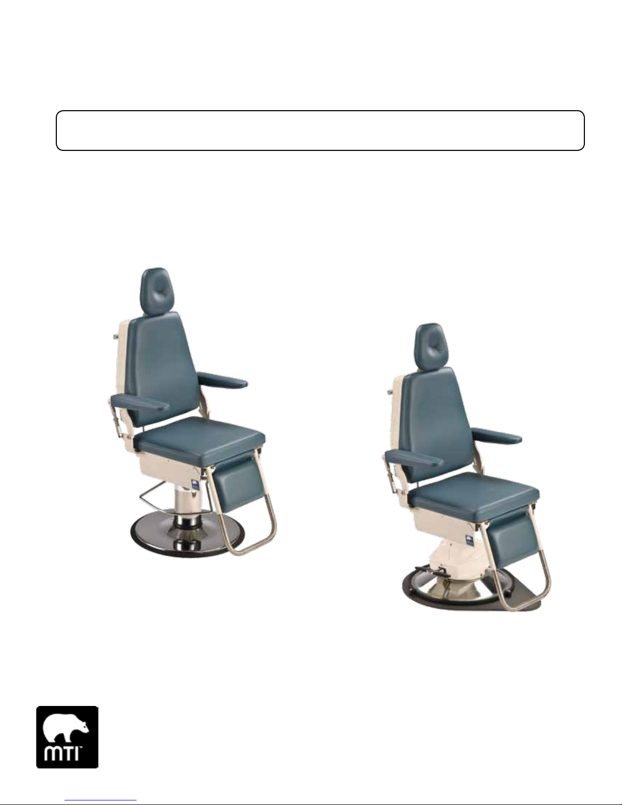
400 & 401 Chairs
CHAIR
Strength in patient care.
™
CHAIR
U.S. & Canada (888) 520-4998
International (801) 875-4998
www.mti.net
Page 2

THIS PAGE IS INTENTIONALLY BLANK.
Page 3

Table of Contents iii
APPLICABLE MODEL(S) .....................................................................................................................................................................................................................................................................................IV
REVISION HISTORY TABLE ........................................................................................................................................................................................................................................................................... IV
GENERAL INFORMATION .....................................................................................................................................................................................................................................................................................
Purpose of this Manual ......................................................................................................................................................................................................................................................................... 1
Intended Use ......................................................................................................................................................................................................................................................................................................... 1
Symbols and Warnings..........................................................................................................................................................................................................................................................................2
Symboles et Avertissements .........................................................................................................................................................................................................................................................2
Safety Instructions .......................................................................................................................................................................................................................................................................................3
Electromagnetic Interference ......................................................................................................................................................................................................................................................4
Electrical Requirements (401 Only) .................................................................................................................................................................................................................................... 4
Contraindications ...........................................................................................................................................................................................................................................................................................5
Transportation and Storage Conditions ........................................................................................................................................................................................................................5
Disposal of Equipment ..........................................................................................................................................................................................................................................................................5
EQUIPMENT FEATURES .......................................................................................................................................................................................................................................................................................
INSTALLATION .....................................................................................................................................................................................................................................................................................................................
Required Tools ....................................................................................................................................................................................................................................................................................................7
Optional Tools ...................................................................................................................................................................................................................................................................................................7
Explanation of Instructions .............................................................................................................................................................................................................................................................7
Unpacking and Set-up ........................................................................................................................................................................................................................................................................ 8
OPERATION ............................................................................................................................................................................................................................................................................................................................
Operating Conditions ..............................................................................................................................................................................................................................................................................9
Controls ...................................................................................................................................................................................................................................................................................................................... 9
Headrest Operation ................................................................................................................................................................................................................................................................................... 9
Manual Backrest Operation .......................................................................................................................................................................................................................................................10
Flip-up Armrest Operation .........................................................................................................................................................................................................................................................10
Electric Base Operation (401) ..................................................................................................................................................................................................................................................10
Manual Base Operation (400) ...............................................................................................................................................................................................................................................10
LIST OF ACCESSORIES ........................................................................................................................................................................................................................................................................................
MAINTENANCE .................................................................................................................................................................................................................................................................................................................
Cleaning and Disinfection ..............................................................................................................................................................................................................................................................13
Preventative Maintenance ..............................................................................................................................................................................................................................................................13
Calls for Service ............................................................................................................................................................................................................................................................................................ 14
LIMITED WARRANTY ..............................................................................................................................................................................................................................................................................................
TROUBLESHOOTING GUIDE ......................................................................................................................................................................................................................................................................
SPECIFICATIONS ...........................................................................................................................................................................................................................................................................................................
Page 4
iv User Manual | MTI 401 & 400
APPLICABLE MODEL(S)
This manual is for the following part numbers and serial numbers:
PART NUMBER DESCRIPTION
4000000 400 Exam Chair 020108003-Current
4000025 401 Exam Chair, 115V 010829010-Current
EFFECTIVE S/N
REVISION HISTORY TABLE
DATE REVISION CO#/ECO# DETAILS
11/13/2001 111301 Initial Release
ORG Corrected website, simplifed instructions, etc.
3/17/2017 A CO-0061 Update Manual to new manual format
Page 5

User Manual
MTI 401 & 400 Chairs
GENERAL INFORMATION
Purpose of this Manual
This manual covers the safety, installation, instructions for use, and maintenance
of this equipment. It is intended that it be used by the service professional
installing the equipment and by the medical professionals who have been trained
to use it. No repair information is included with this manual, because no operator
repairs are intended.
Intended Use
This equipment is intended to be used as a chair for general examinations and
procedures performed by medical professionals.
PRODUCT INFORMATION
Date of Purchase:
Model Number:
Serial Number:
(see “EQUIPMENT FEATURES” on page 6 for location of serial number label)
Page 6
2 User Manual | MTI 401 & 400
Symbols and Warnings
This manual contains Notices, Cautions, and Warnings,
which are meant to call attention to particular parts
or sections of this manual. Since safety is our first
concern, this manual should be read by all personnel
who will be operating this medical equipment. Failure
to comply with the following warnings and cautions
will void the warranty.
Symboles et Avertissements
Ce manuel contient des avis, des précautions et des
avertissements qui sont destinés à attirer l’attention sur
des pièces ou des sections de ce manuel particulier.
Parce que la sécurité est notre première préoccupation,
ce manuel doit être lu par tout le personnel qui
sera d’utiliser cet équipement médical. Défaut de se
conformer avec les avertissements et les précautions
de ce guide d’instruction annulera la garantie.
WARNINGS/AVERTISSEMENTS
Are used to call attention to a condition, practice, or
procedure which could cause personal injury if not
followed correctly. Please become familiar with all
warnings and observe them at all times.
Sont utilisés pour attirer l’attention sur une condition,
pratique ou procédure qui pourrait causer des blessures
s’il n’est pas suivi correctement. S’il vous plaît se
familiariser avec tous les avertissements et les observer
à tout moment.
CAUTIONS/PRECAUTIONS
Are used to call attention to a condition, practice, or
procedure which could cause product damage if not
used correctly.
Sont utilisés pour attirer l’attention sur une condition,
pratique ou procédure qui pourrait causer des
dommages au produit s’il n’est pas utilisé correctement.
NOTICES/AVIS
Are used to call attention to helpful information
regarding a condition, practice, or procedure.
Sont utilisés pour attirer l’attention sur des informations
utiles concernant une condition, pratique ou de procédure.
2
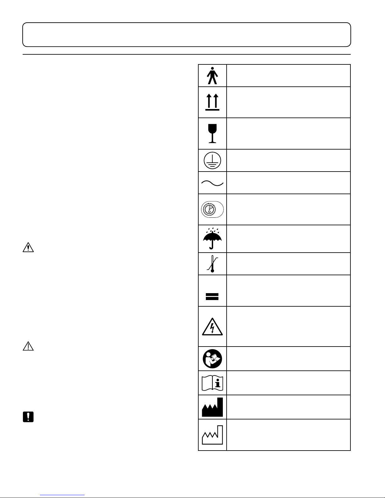
Class 1, Type B, Medical Equipment
Proper shipping orientation for the product
Orientation d’embarquement correct pour
le produit
Product is fragile; be careful in handling
Le produit est fragile. Soyez prudent lors
de la manipulation
Protective earth ground
Terre électrique de protection
Alternating current
Le courant alternatif
Unit duty cycle of 10% Example: (1) minute
15 sec
on (9) minutes o.
5 min
Unité rapport cyclique du 10%
Product must be kept dry
Le produit doit rester sèche
Upper and lower limits of temperature
Limites haute et basse de la température
Maximum stacking height of palletized units.
Hauteur maximale de la pile d’unités sur
palettes.
Indicates the presence of a dangerous
voltage/shock hazard
Indique le présence de voltage
dangereux/ de choc
Follow instructions for use
Suivez les instructions pour l’utilisation
Consult operating instructions
Consultez les instructions d’utilisation
Manufacturer of product
Fabricant de produits
Date on which the product was
manufactured
Date de fabrication
Page 7
User Manual | MTI 401 & 400 3
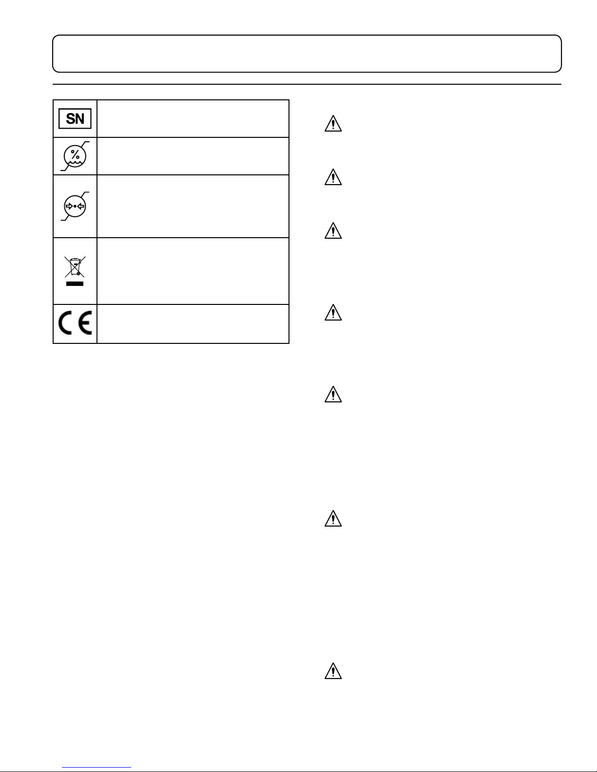
Identifies the manufacturer’s serial number
Identifie le numéro de série du fabricant
Upper and lower limits of relative humidity
Limites haute et basse de humidité relative.
Upper and lower limits of atmospheric pressure
Limites haute et basse de la pression
atmosphérique
(WEEE) Waste of Electrical and Electronic
Equipment
Déchets d’équipements électriques et
électroniques
European Conformity mark
Marque Conformité Européenne
Safety Instructions
WARNING/AVERTISSEMENT
Read this manual before installation and use.
Lisez ce manuel avant l’installation et l’utilisation.
WARNING/AVERTISSEMENT
No modification of this equipment is allowed.
Aucune modification de cet équipement est autorisé.
WARNING/AVERTISSEMENT
Do not operate equipment in the presence of
flammable anesthetics.
Ne pas faire fonctionner l’équipement en présence
d’anesthésiques inflammables.
WARNING/AVERTISSEMENT
Verify equipment, patient, and other objects are in a safe
condition before operating the equipment.
Vérifiez l’équipement, patient, et d’autre objets sont dans
un état sûr avant d’utiliser l’équipement.
WARNING/AVERTISSEMENT
Verify controls, cords, and other parts of the equipment
do not create a tripping or other safety hazard for
operator or patient.
Vérifiez les contrôles, les cordons et les autres
parties de l’équipement ne créent pas un risque de
trébuchement ou d’autres risques d’accident pour
l’opérateur ou le patient.
WARNING/AVERTISSEMENT
Backrest, seat, footrest, armrest, headrest, and other
parts of the equipment should only be used for their
intended purpose. MTI is not responsible for use of
components outside of their intended use.
Le repose-dos, reste de siège, repose pieds, accoudoirs,
appuie-tête et d’autres parties de l’équipement ne
doivent être utilisés conformément à leur utilisation
prévue. MTI n’est pas responsable de l’utilisation des
composants au dehors de leur utilisation prévue.
WARNING/AVERTISSEMENT
This product contains chemicals known to the State of
California to cause cancer and/or birth defects or other
reproductive harm. See http://www.mti.net/FAQs.aspx for
details on California Proposition 65.
Page 8
4 User Manual | MTI 401 & 400
Ce produit contient des produits chimiques reconnus
par l’État de Californie pour causer le cancer et / ou
des anomalies congénitales ou d’autres problèmes de
reproduction. Voir http://www.mti.net/FAQs.aspx pour
plus de détails sur la California Proposition 65.
Electromagnetic Interference
This equipment is designed and built to minimize
electromagnetic interference with other devices. However,
if interference is noticed between another device and this
equipment, do one or more of the following:
1. Plug the equipment into an isolated circuit.
2. Remove the interfering device from the room.
3. Increase the separation between the equipment
and the interfering device.
4. Contact MTI if the electromagnetic interference
persists.
Electrical Requirements (401 Only)
WARNING/AVERTISSEMENT
To avoid risk of electrical shock, this equipment must be
connected to a supply mains with protective earth.
Pour éviter tout risque de choc électrique, cet
équipement doit être branché sur une prise électrique
avec la terre électrique de protection.
WARNING/AVERTISSEMENT
Grounding reliability can only be achieved when the
equipment is connected to an equivalent receptacle
marked “Hospital Only” or “Hospital Grade”.
Mise à la terre fiabilité ne peut être atteint lorsque
l’équipement est connecté à un réceptacle équivalent
marqué “Hôpital Uniquement” ou “de Qualité Hôpital”.
non-respect peut entraîner un choc électrique ou de
brûlures pour le patient.
WARNING/AVERTISSEMENT
Connecting electrical equipment to a multiple socketoutlet eectively leads to creating a medical electronic
system and can result in a reduced level of safety.
Connexion d’un équipement électrique à une prise
de courant multiple crée un système électronique
médicale, et peut entraîner une baisse du niveau de
sécurité.
WARNING/AVERTISSEMENT
Equipment must be positioned in normal use such that
the power cords can be easily accessed to unplug.
L’équipement doit être positionné en utilisation normale
telle que les cordons d’alimentation peuvent être
facilement accessibles à débrancher.
WARNING/AVERTISSEMENT
Equipment must be connected to an appropriate power
source when loss of power source would result in an
unacceptable risk.
L’équipement doit être relié à une source d’alimentation
appropriée en cas de perte de la source d’alimentation
entraînerait un risque inacceptable.
WARNING/AVERTISSEMENT
Do not use a two-three plug adapter to plug the
equipment into a two conductor outlet, as grounding
reliability is not maintained.
Ne pas utiliser un adaptateur non de prise de
terre pour brancher l’équipement sur une prise à
deux conducteurs, la fiabilité de la terre n’est pas
maintenue.
WARNING/AVERTISSEMENT
When using endocardial catheters or high frequency
surgical/procedure devices, use non-conductive material
to insulate the patient from metal portions of the
equipment. Failure to comply may result in electric
shock or burns to patient.
Lors de l’utilisation de cathéters endocavitaires ou
dispositifs chirurgicale / procédure haute fréquence,
utiliser un matériau non conducteur pour isoler le
patient des parties métalliques de l’équipement. Le
WARNING/AVERTISSEMENT
Do not plug this equipment into a low power or
auxiliary outlet. This equipment must be connected to
a 115 Volt (V) outlet. If this equipment is connected to
an insucient power source, it will cause irreparable
damage to this device’s electronics.
Ne branchez pas cet équipement sur une prise de
faible puissance ou une prise auxiliaire. Cet équipement
doit être branché sur une prise de 115 Volt (V). Si cet
équipement est connecté à une source d’alimentation
Page 9
User Manual | MTI 401 & 400 5
insusante, il causera des dommages irréparables à
l’électronique de cet appareil.
CAUTION/PRÉCAUTION
An appropriately rated surge protector must be used to
protect the printed circuit board. Warranty is void if this
surge protector is not used.
Un protecteur de surtension correctement classé doit être
utilisé pour protéger la carte de circuit imprimé. La garantie
est nulle si, ce protecteur de surtension n’est pas utilisé.
NOTICE/AVIS
Removing the power supply cord at the wall receptacle
will simultaneously isolate both poles of the power supply.
Retrait du cordon d’alimentation à la prise murale se
isoler simultanément les deux pôles de l’alimentation.
Contraindications
None.
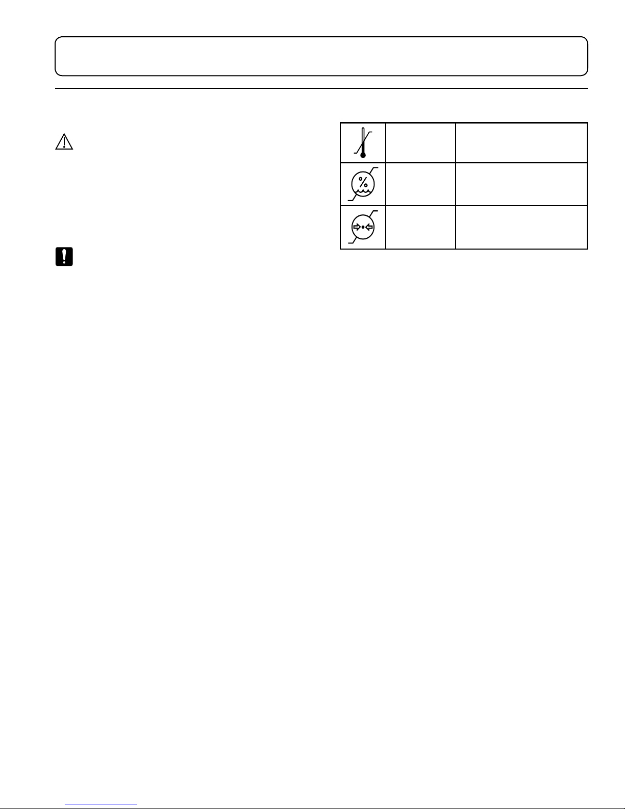
Transportation and Storage Conditions
Ambient
Temperature
Relative
Humidity
Atmospheric
Pressure
+10°C to +40°C
(+50°F to +104°F)
30% to 75%
(non-condensing)
700hPa to 1060hPa
(0.69atm to 1.05atm)
Disposal of Equipment
At the end of product life, the equipment, accessories,
and other consumable goods may have become
contaminated due to normal medical use. Consult
local codes and ordinances for proper disposal of
equipment, accessories and other consumable goods.
Page 10
6 User Manual | MTI 401 & 400
Headrest Height
Adjustment Knob
Calf Pad
Headrest
Backrest
Seat
Flip-up Armrest
Manual Back Lever
Up Pedal
Down Pedal
Lift Lever
& Swivel
Brake
400
Serial Number Label
Swivel Brake
Looped Footrest
EQUIPMENT FEATURES
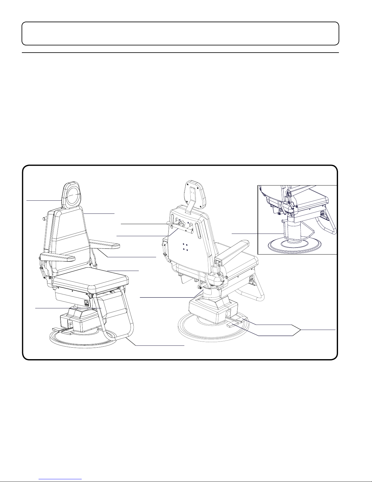
Description of 400 Exam Chair
The 400 Exam Chair includes an 8” manual hydraulic lift and gas spring assisted manual back. The 400 chair is 19.5”
(49.5 cm) wide. The chair is used for positioning a patient for exams. The 400 Exam chair also has the ability to swivel.
Description of 401 Exam Chair
The 401 Exam Chair includes an 8” electric power lift and gas spring asssisted manual back. The 401 Exam Chair is
19.5" (49.5 cm) wide. The chair is used for positioning a patient for exams. The 401 Exam chair also has the ability to
swivel.
/ EXAM CHAIR
Page 11
User Manual | MTI 401 & 400 7
INSTALLATION
WARNING/AVERTISSEMENT
This equipment is heavy. Get help to remove it from
the shipping pallet. Use proper lifting procedures when
lifting to avoid serious back injury.
Cet équipement est lourd. Obtenir de l’aide pour le
retirer de la palette d’expédition. Utilisez les procédures
propre de levage pour le soulever pour éviter grave
blessure au dos.
CAUTION/PRÉCAUTION
To move equipment, lift only from the equipment’s
main structure.
Pour déplacer l’équipement, soulevez seulement de la
structure principale de l’équipement.
NOTICE/AVIS
If this product has been exposed to low temperatures,
allow adequate time for it to warm to room temperature
before putting it into service.
Si ce produit a été exposé à de basses températures, laisser
susamment de temps pour lui permettre de se réchauer
à température ambiante avant de le mettre en service.
NOTICE/AVIS
Inspect the shipping boxes for visible damage. Record
on bill of lading, photograph, and report any damage
to the carrier immediately. Request an inspection by the
carrier if any concealed damage is noted.
Inspectez les boîtes d’expédition pour les dommages
visibles. Fiche sur le connaissement, prendre une
photo, et signalez les dommages dûs au transporteur
immédiatement. Demander une inspection par le
transporteur en cas de dommage caché est noté.
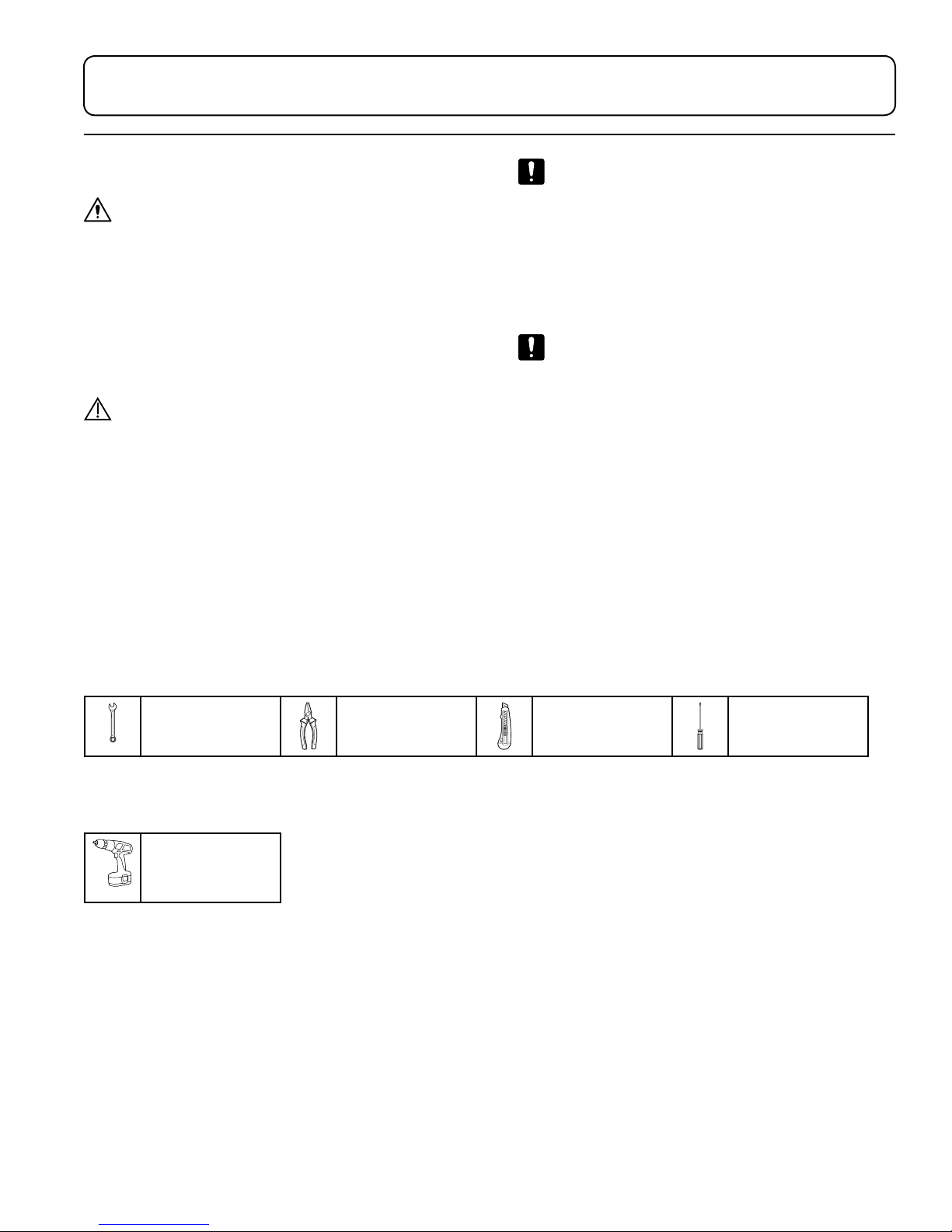
Required Tools
7/16" Wrench Wire cutters Utility Knife Phillips
Screwdriver (#2)
Optional Tools
Impact driver
w/1/2” cement
drill bit
Explanation of Instructions
Instructions have steps which are designated by a number. Each step may also have sub-steps designated by a letter.
For example, an instruction to operate a feature may have 4 steps (1-4) and each of those steps may have sub-steps
(A-B) to be performed before moving on to the next step.
Page 12
8 User Manual | MTI 401 & 400
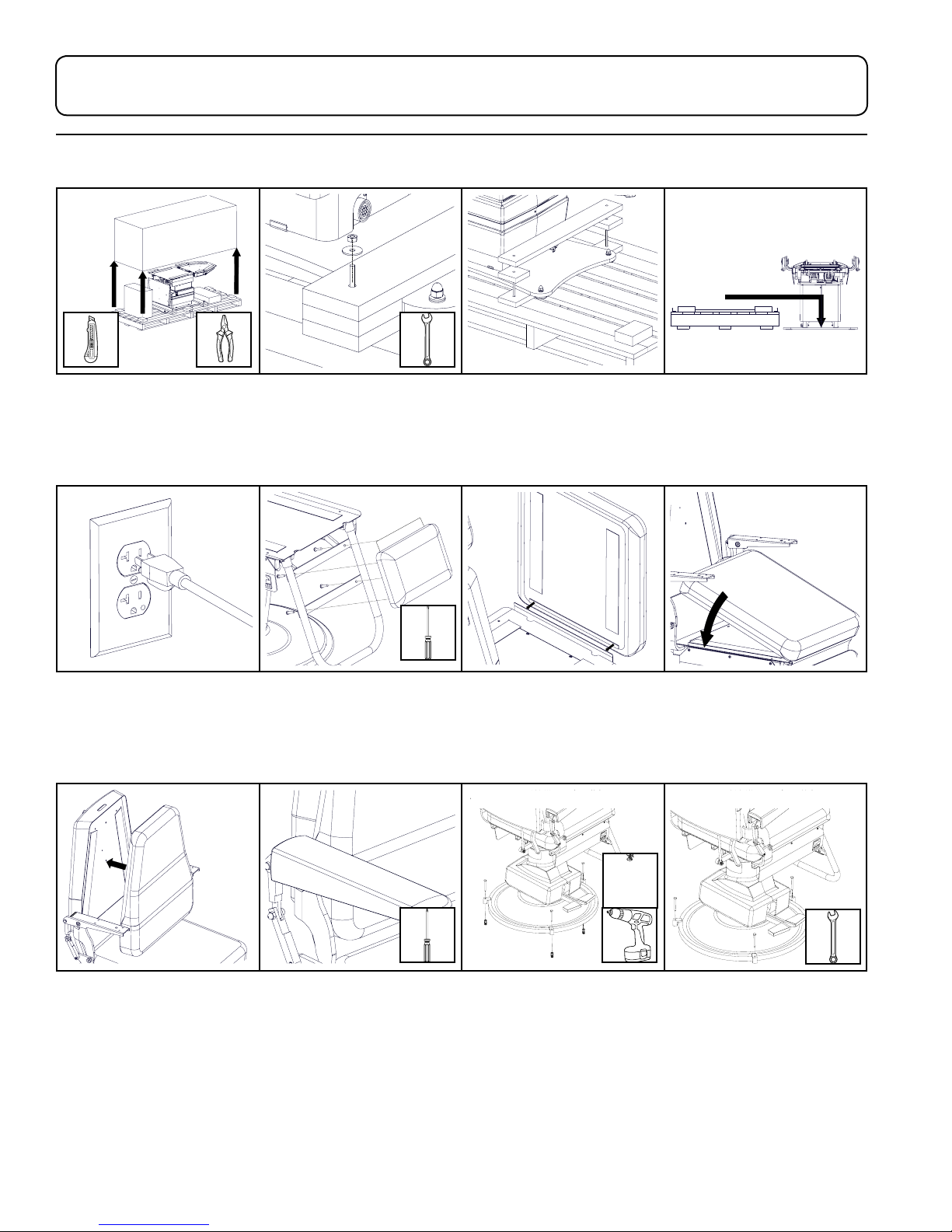
Unpacking and Set-up
1. Remove shipping straps,
shipping box, and other
boxes from the pallet.
5. Plug the power cord into
an appropriately marked
receptacle (401 only).
2. Remove (4) shipping bolts
with 7/16" end wrench.
6. Attach the upholstery flap
to the back of the calf pad.
Align the calf pad with the
foot loop and attach with
the 4 screws from behind.
3. Remove braces from the
top of the baseplate.
7. Attach the flap to the end
of the seat cushion.
For Concrete Floors For Wood Floors
4. Slide chair o pallet. To
move equipment, lift only
from the equipment’s main
structure. Recycle or re-use
pallet.
8. Align the seat cushion
with the seat section of
the chair and press into
place. Verify the cushion is
centered.
9. Align the back cushion
with the back section of
the chair and press into
place. Verify the cushion is
centered.
10. Attach the flip-up arm
upholstery following the
instructions provided in the
upholstery kit.
11. If teardrop baseplate is not purchased, install the floor
clips at 3 points around the base plate. For wood floors
use only the lag bolts. For concrete floors use the lag
bolts and lag shield. To install lag shield drill 1/2” diameter
hole deep enough to insert the lag shield. Tighten lag
bolts with 7/16” wrench.
For chairs purchased with teardrop stabilizer plate, see
teardrop stabilizer plate instructions.
Page 13
User Manual | MTI 401 & 400 9
B
C
A
B
A
C
A
B
C
B
B
A
2,3
4
1, 3
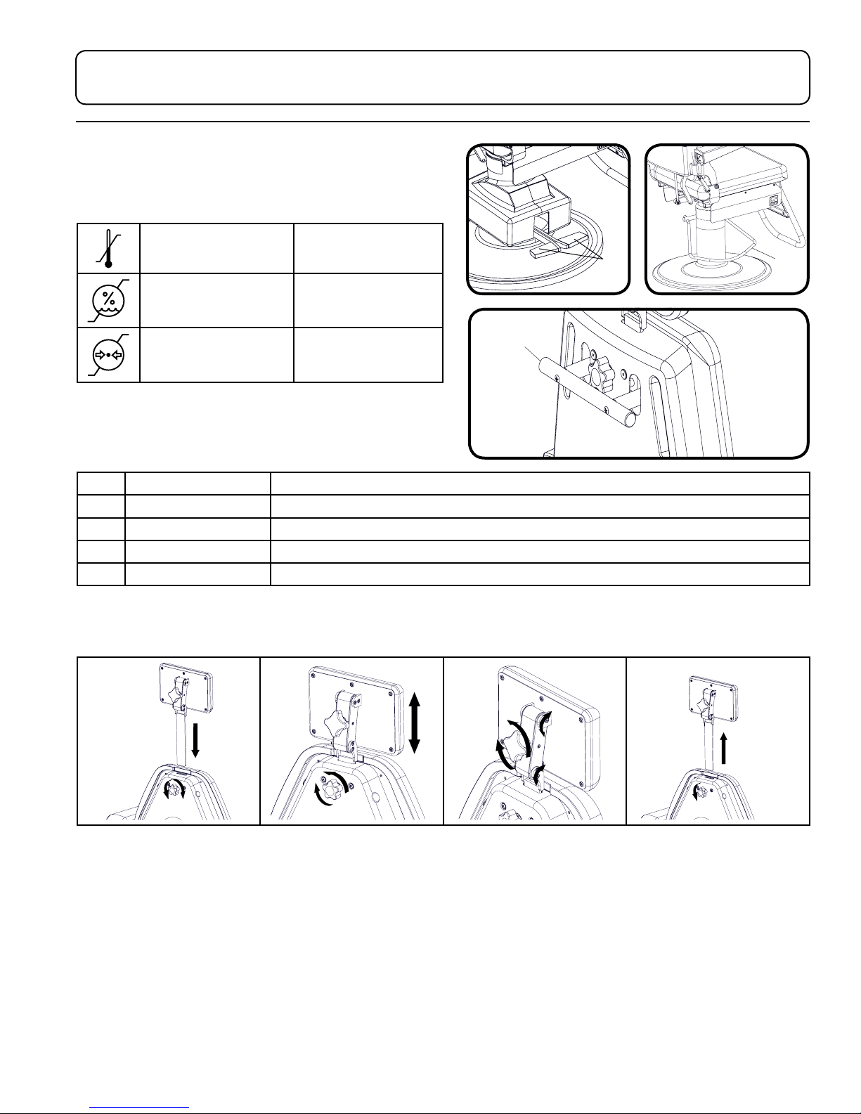
OPERATION
Operating Conditions
Ambient Temperature +10°C to +40°C
(+50°F to +104°F)
Relative Humidity 30% to 75%
(non-condensing)
Atmospheric Pressure 700hPa to 1060hPa
(0.69atm to 1.05atm)
Controls
Lift/Swivel Controls/Back Lever
ITEM DESCRIPTION FUNCTION
1 Up/Down Pedals Raises or lowers the chair top by pressing the desired direction
2 Up/Down Lever Raises or lowers the chair top
3 Swivel Locks and unlocks the chair’s swivel
4 Back Up/Down Lever Move the lever up or down and position the back manually as desired
Headrest Operation
Articulating and Non-Articulating Headrests
1. To install the headrest:
A. To loosen, turn the knob
on the back of the chair
counterclockwise.
B. Insert the headrest
through the slot in the top
of the backrest.
C. To secure, turn the knob
clockwise.
2. To adjust the height of
the headrest:
A. To loosen, turn the knob
on the back of the chair
counterclockwise.
B. Adjust the height of the
headrest.
C. To secure, turn the knob
clockwise.
3. To adjust the angle of the
headrest (Articulating only):
A. To loosen, turn the knob
on the back of the headrest
counterclockwise.
B. Adjust the position and
angle of the headrest.
C. To secure, turn the knob
clockwise.
4. To remove a headrest:
A. To loosen, turn the knob
on the back of the chair
counterclockwise.
B. Pull the headrest
completely out of the back.
Page 14
10 User Manual | MTI 401 & 400
DOWN
UP
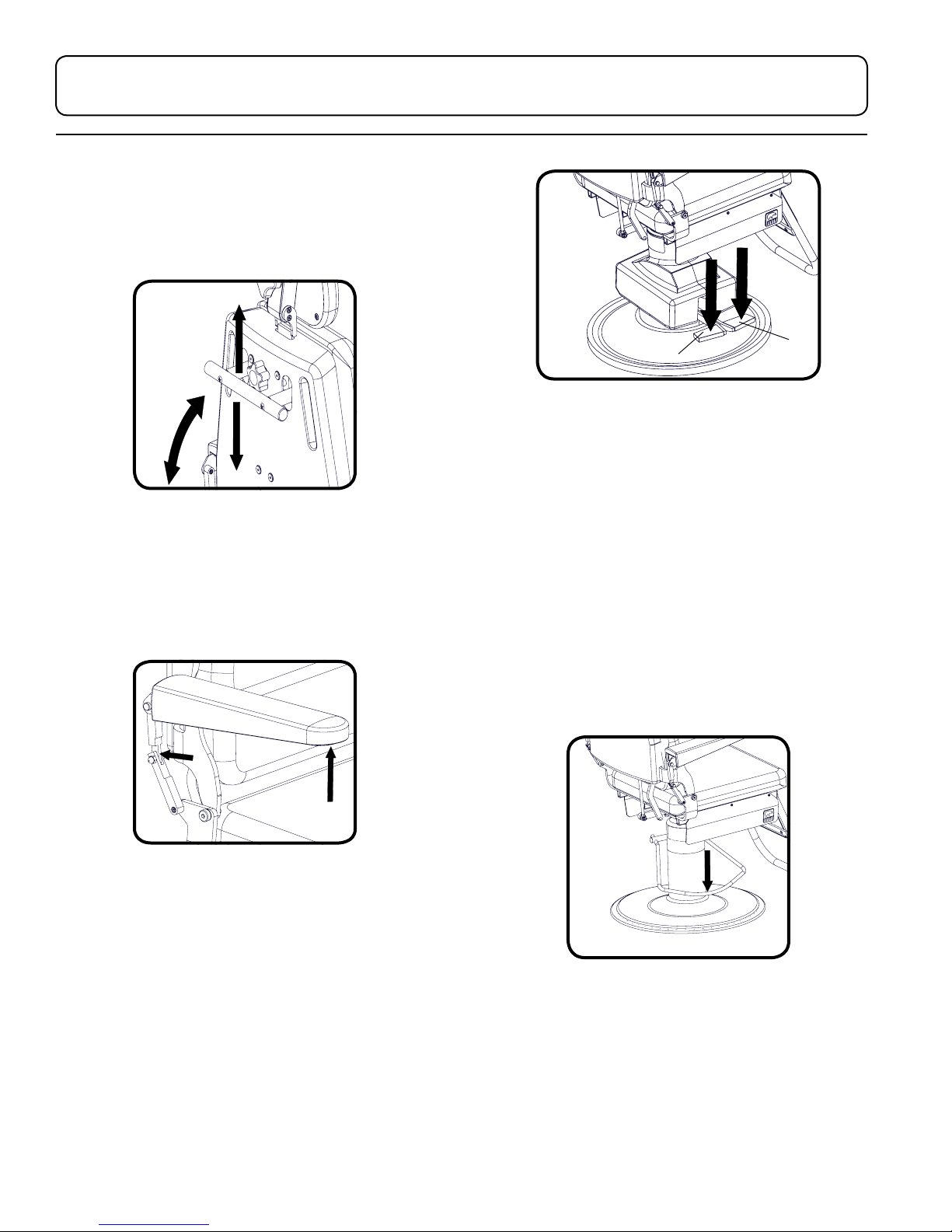
Manual Backrest Operation
To position the backrest, pull up or down on the lever
on the back of the chair, position the backrest to the
desired location, then release the lever (Figure 1).
Figure 3
Manual Base Operation (400)
Figure 1
Flip-up Armrest Operation
To raise the armrest, press the joint of the arm
backwards while lifting the front of the arm (Figure 2).
Figure 2
To lower the armrest, swing the arm down. The joint
will lock in place when fully lowered.
To raise the chair, pump the lever at the base of the
chair down, repeating as necessary to move the chair
higher.
To lower the chair, push down on the lever all the way and
hold in place until the chair reaches the desired height.
To lock the swivel of the chair, lift up on the lever slightly.
To unlock the swivel of the chair, push the lever down
slightly (Figure 4).
Electric Base Operation (401)
To raise the chair: press down on the pedal marked
with a “U” (Figure 3).
To lower the chair, press down on the pedal, marked
with a “D” (Figure 3).
To lock the swivel of the chair, lift up on both pedals.
To unlock the swivel press down on either pedal.
Figure 4
Page 15
User Manual | MTI 401 & 400 11
LIST OF ACCESSORIES
DESCRIPTION USE RESTRICTIONS
Headrest, Articulating Oval, Deep
Oval, Rectangular, Prosthetic, Round
Headrest, Non-Articulating Oval,
Rectangular
Light, LED Exam Provides lighting during patient
Teardrop Stabilizer Plate Provides a larger base with more
Provides a dual articulating surface
with various pillow shapes/sizes to
support patient’s head.
Provides a surface with oval or
rectangular pillow shapes which do
not articulate.
Not available with paper roll holder.
procedures.
weight towards the front of the chair.
Paper Roll Holder (18”) Used for mounting a paper roll to
the back of the chair.
18” (45.7cm) Not compatible with
back mounted exam light.
Page 16
12 User Manual | MTI 401 & 400
MAINTENANCE
WARNING/AVERTISSEMENT
There are no user serviceable parts inside. Refer all
servicing to a qualified service technician.
Aucune pièce interne ne peut être réparée par
l’utilisateur. Adressez-vous à un technicien qualifié.
WARNING/AVERTISSEMENT
The Control of Hazardous Energy (lockout/tagout)
§1910.147 procedure must be followed to disable
equipment, preventing the release of hazardous energy
while performing servicing and maintenance activities.
La procédure de La Maîtrise des Énergies Dangereuses
(lockout/ déconsignation) § 1910.147 doit être suivie pour
désactiver l’équipement, empêchant la libération des
énergies dangereuses lors de l’exécution des activités de
maintenance et d’entretien.
CAUTION/PRÉCAUTION
This equipment may be damaged by solvents and dyes.
Immediately remove any fluids spilled on the equipment.
CAUTION/PRÉCAUTION
Any sprayed disinfectant or cleaning solution should be
wiped up immediately after application and not let to
stand. A small sample area should be tested before any
large application of any cleaner/disinfectant.
Tout désinfectant pulvérisé ou solution de nettoyage
doivent être essuyés immédiatement après l’application
et ne pas laisser reposer. Une petite zone de
l’échantillon doit être testé avant toute application
complète d’un nettoyant/désinfectant.
CAUTION/PRÉCAUTION
Avoid prolonged direct sunlight exposure to preclude
color change of the plastic.
Évitez l’exposition directe au soleil prolongée pour empêcher
le changement de couleur des éléments en plastique.
NOTICE/AVIS
MTI recommends cleaning the equipment frequently.
MTI recommande de nettoyer l’équipement fréquemment.
Cet équipement peut être endommagé par des solvants
et des colorants. Retirer immédiatement tout liquide
renversé sur l’équipement.
CAUTION/PRÉCAUTION
Avoid contact with sharp or pointed objects. Do not
place hard surface objects on the upholstery surfaces as
temporary indentations or impressions in the upholstery
cover will result. Prolonged contact with a hard or
irregular shaped object may make the impression semipermanent.
Éviter le contact avec des objets pointus ou tranchants.
Ne placez pas d’objets de surfaces dures sur les surfaces
de capitonnage d’ameublement, comme des empreintes
temporaires ou des impressions dans le couvercle du
capitonnage en résulteront. Un contact prolongé avec
un objet en forme de disque ou irrégulière peut faire
l’impression semi-permanente.
Page 17

User Manual | MTI 401 & 400 13
Cleaning and Disinfection
Upholstery
Upholstery should be cleaned weekly with a mild
liquid soap and water mixture. Afterwards, wipe
upholstery with a clean damp cloth.
MTI’s standard policy on disinfecting MTI medical
equipment is to use a 10% sodium hypochlorite
(bleach) and 90% water solution. If stronger or other
disinfecting and cleaning solutions are used, the
surface is at risk to be damaged or possibly cause
discoloring, cracking, or other types of damage to the
surface. See current CDC Guideline for Disinfection
and Sterilization in Healthcare Facilities.
MTI understands that many customers prefer to use a
pre-mixed disinfecting solution in a spray or wipe. It is
MTI’s recommendation not to use sprays because over
time the overspray will cause damage to the surfaces
if not immediately wiped up. MTI recommends hand
towels or wipes to avoid the possibility of overspray.
Once the approved contact time has been obtained,
remove and dry excess liquid remaining on the surface.
Preventative Maintenance
Periodically inspect the following areas:
1. All fasteners and pins should be in place and
tightened securely.
2. Lubricate pins and moving joints as needed with
lithium grease.
3. Power cord should be free of cuts or other visible
damage.
4. All mechanical functions should operate properly.
Have an authorized service technician inspect your
equipment once a year.
See “MTI Cleaning Solution Recommendation Letter”
for more details on disinfecting solutions which have
been tested on MTI’s products. It is available for
download at http://www.mti.net/downloads.aspx in
the Product Support Bulletins folder, found under the
Resources tab on our website. In the U.S. & Canada,
call (888) 520-4998, or International, call (801) 8754998 to request a copy.
Painted and Plastic Surfaces
All painted metal parts have been electrostatically
painted and the paint is baked on for durability. These
surfaces should be wiped down with a quality grade
cleaner and a soft cloth or a damp cloth with mild
soap once a week.
Page 18

14 User Manual | MTI 401 & 400
Calls for Service
Equipment’s model and serial number information are
required when calling for service.
Serial number is indicated by the symbol
located on the serial number tag.
If service is required, contact MTI
U.S. & Canada 888-520-4998
International 801-875-4998
Fax (801) 952-0548
[email protected]
Monday-Friday 8:00 am - 5:00 pm (MST)
www.mti.net
LIMITED WARRANTY
Medical Technology Industries, Inc. (hereinafter referred to
as MTI), shall repair or replace products of its manufacture,
which prove to be defective in material and/or workmanship
for a period of twelve (12) months from the date of
shipment to the customer (the “Warranty Period”). MTI will,
at its option, provide parts to the customer or repair the
defective part at MTI’s factory or authorized repair facility.
Except as it may otherwise specifically agree in writing, MTI
shall not be liable for transportation or labor charges for
repairs or adjustments or other work done on any of its
products by MTI’s authorized dealers or service organizations.
Customer shall notify MTI of any alleged claim or defect
within fourteen (14) days from the date customer discovers,
or upon reasonable inspection should have discovered,
such alleged claim or defect (but in any event before the
expiration of the Warranty Period). All repair parts are
warranted for Ninety (90) calendar days from the date of
shipment to the customer. Warranty is non-cumulative.
This warranty does not apply to any part or product
which upon examination by MTI or its authorized agents
indicates the product has been repaired or altered in any
way by persons other than MTI or its authorized agents,
has been misused, abused or used in a manner contrary
to any instructions issued by MTI. Any parts or products
claimed under this warranty must be properly packaged by
customer and returned to MTI’s factory with no liability to
MTI for the parts, products or transportation charges thereon.
In no event, shall MTI have any liability for consequential,
indirect, incidental, special, exemplary, punitive or enhanced
damages, lost profits or diminution in value arising
out of or relating to a product defect or the repair or
replacement of any products manufactured or sold by it.
THE FOREGOING LIMITED WARRANTY IS MADE IN LIEU OF ALL
WARRANTIES EXPRESSED OR IMPLIED, AND MTI MAKES NO OTHER
WARRANTY WHATSOEVER WITH RESPECT TO THE PRODUCTS
INCLUDING BUT NOT LIMITED TO, ANY IMPLIED WARRANTY OR
MERCHANTABILITY OR FITNESS FOR A PARTICULAR PURPOSE.
Page 19
User Manual | MTI 401 & 400 15
TROUBLESHOOTING GUIDE
NOTICE/AVIS
For more information on this equipment, including circuit diagrams, parts and service manuals, and other descriptions,
please contact MTI.
Pour plus d’informations sur cet équipement, y compris des schémas de circuits, les manuels de service et pièces, et
autres descriptions, s’il vous plaît contacter MTI.
# SYMPTOM PROBLEM CAUSE SOLUTION
1 Chair will not function. Chair power cord is not plugged in. Verify power cord is securely
connected at both ends.
2 Chair will not function. Facility power receptacle problem. Check facility’s power receptacle
with a known working device of
same voltage specifications.
3 Chair will not function. Facility power receptacle problem. Check facility circuit breaker to
verify it is not tripped.
4 Chair will not function. Facility supply voltage is incorrect
voltage.
Verify voltage is per specifications
on chair serial number/product tag.
SPECIFICATIONS
DESCRIPTION SPECIFICATION
Lifting Capacity 400: 250 lbs (113.4 kg) 401: 350 lbs (158.8 kg)
Weight of Chair*
400
401
Shipping Weight of Chair*
400
401
Table Top Range 19” (48.3 cm) to 27” (68.6 cm)
Back Section Range 0° (horizontal) to 82° ± 5°
General Dimensions (with headrest retracted) 19.5" (49.5 cm) wide x 43" (109.2 cm) long
Power Cord: 401 only
Electrical Ratings: 401 only 115 VAC ± 10%, 2.78 amps, 60 HZ
Classification Class 1, Type B Equipment, Ordinary Equipment, Intermittent
*Weight and dimensions may vary depending on accessories purchased and international shipment weights and
dimensions may vary.
137 lbs (63 kg)
170 lbs (78 kg)
224 lbs (102 kg)
257 lbs (117 kg)
Plugs: U.S.A. standard 3 prong
Operation
Page 20

Strength in patient care.
™
Salt Lake City, Utah, 84104-6572
3655 W Ninigret Drive
(800) 924-4655 • (801) 875-4999 • Fax (801) 952-0548
www.mti.net
© MTI, Inc. All rights reserved.
MTI reserves the right to make any
product changes without notice.
073001 Rev A
 Loading...