

MTHTrains RealTrax O-3, RealTrax O-31 User Manual
MTH
ELECTRIC TRAINS, INC.
7020 Columbia Gateway Drive
Columbia, MD 21046-1532
O-31
SWITCH
®
MTH RealTrax switches add flexibility
and reliability to your O Gauge RealTrax
layout. Designed to provide years of
trouble free, smooth operation, RealTrax
switches are the
perfect additions
to expand your
®
RailKing empire.
®

Table of Contents
Introduction: 3
Switch Operating Instructions: 4
®
RealTrax O-31 Switch Components: 4
Screw Terminal Definition: 6
Remote Switch Wiring Instructions: 7
Basic Switch Operation: 7
Changing Switch Block Positions: 8
Accessory Operation From Switch Power Out: 9
Multiple Connections Under Screw Terminal 9
Multiple Switch Operating Instructions (Track Power): 9
Multiple Switch Operation Through One Remote Switch, 9
Track Power, Identical Throws:
Multiple Switch Operation Through One Remote Switch, 10
Track Power, Opposite Throws:
Auxiliary Powered Switch Operating Instructions: 10
Multiple Switch Operation Through Separate Remote Switches 11
Multiple Switch Operation Through One Remote Switch, 11
Auxiliary Power, Identical Throws
Multiple Switch Operation Through One Remote Switch, 12
Auxiliary Power, Opposite Throws
®
RealTrax O-31 Switches In Tubular Rail Layouts: 13
Multiple Train Operation Using Powered/Unpowered Sidings: 14
Troubleshooting 15
Service and Warranty Information 16
Operating Caution 16
How to Get Service Under The Terms of The Limited One Year Warranty 16
Limited One Year Warranty 16
2

Introduction
Thank you for purchasing the MTH Electric Trains RealTrax O-31 Switch. As
with all RealTrax products, you will find the O-31 Switch easy to install into
your layout whether it be a permanent or temporary one. There are no
plastic and/or metal pins to lose or confuse. The setup is simple; with only
three connections of easy to attach connectors and the turn of a screw, your
RealTrax Switch will be up and running in no time!
The RealTrax O-31 Switch performs all of the functions of other switches, but
better. It has a double-microswitch driven non-derailing feature. Inside the
Switch Block (lantern housing) are four powerful but efficient and quiet
solenoid coils that drive the switch points back and forth at a voltage and
current draw as yet unexperienced in model railroading. The RealTrax Switch
operates on only 10Volts and 1.25Amps. It has a spring assisted mechanism
that ensures that the points always will be in the correct position. If you
change directions with a RealTrax Switch, you will not have to worry about
derailments or electrical short circuits.
The RealTrax Switch can be wired for operation via track power or auxiliary
power. Also, you will be able to operate several RealTrax Switches together
by following the appropriate illustrated diagram(s) in this manual. It can be
installed into a layout to have powered and unpowered sidings for multiple
train operation (see figure 14).
The RealTrax O-31 Switch is constructed of sturdy ABS plastic, solid extruded
rails and simple yet sturdy electronics. The design has been streamlined with
features like a Switch Block Cover that hides the opening to the switch's
underside and a Screw Terminal Cover that hides the traditionally unsightly
yet necessary wire connections. The design follows other RealTrax items so
that it blends into your layout, instead of standing out. With its ruggedness
and slim styling, the RealTrax O-31 Switch will give you years of trouble-free
operation on either your RealTrax or your tubular rail O-Gauge model
railroad.
3

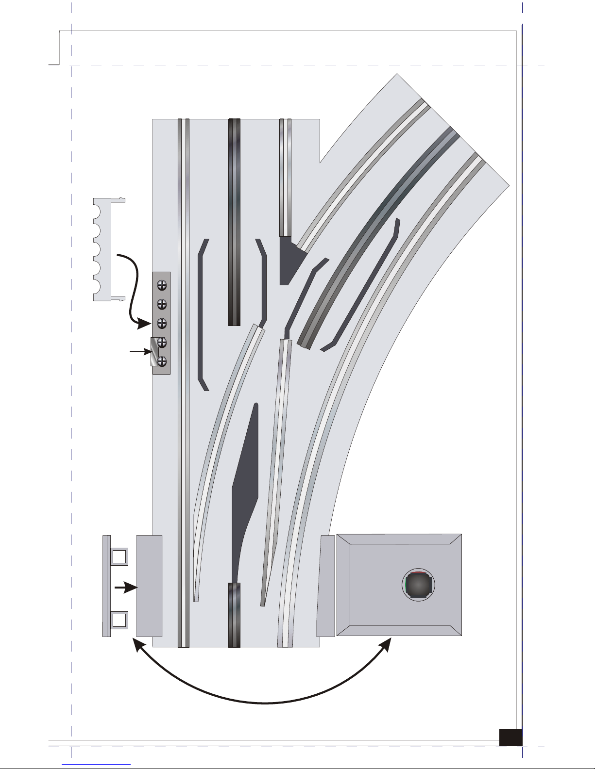
1) Switch:
Consists of the roadbed, rails, points, frog, screw terminals, operating
circuitry and mechanisms.
2) Screw Terminal Cover:
Plastic cover that attaches to the roadbed and conceals the screw terminals.
3) Jumper:
Removable metal connector between 4th and 5th screw terminals. The
Jumper acts as a switch between track and auxiliary power.
4) Switch Block:
Consists of housing, solenoid coils and lantern. The Switch Block attaches
to either rectangular port at the converging end of the Switch. The Switch
Block may be attached to either side of the switch.
(See Figure 4)
5) Switch Block Cover:
Plastic cover that attaches to and conceals the unused Switch Block port.
6) Remote Switch:
Separate manual switch with momentary action. The Remote Switch can
operate your switch from anywhere on your layout.
RealTrax O-31 Switch Components:
®
RealTrax O-31 Switch Operating Instructions:
4
6
5
1
2
3
4
5
Figure 1a:
 Loading...