

MTHTrains Premier 2-4-1A Mountain Operator's Manual

Premier 2-4-1A Mountain
Steam Locomotive
OPERATOR’S MANUAL
PLEASE READ BEFORE USE AND SAVE
Passenger Station Announcement
3
Compatibility
This engine is available in 2-Rail and 3-Rail
versions and will operate on any traditional
O-54 Gauge 3-Rail track system. Or any 54”
radius 2-Rail track system. It is also
compatible with most standard AC
transformers and DC power packs. (See
pages 42 and 43 for a complete
list of compatible AC transformers and DC
power packs.

This product may be protected by one or more of the following patents: 6,019,289; 6,280,278; 6,281,606; 6,291,263;
6,457,681; 6,491,263; 6,604,641; 6,619,594; 6,624,537; 6,655,640.
©2011, M.T.H. Electric Trains®, Columbia, MD 21046
CAUTION: ELECTRICALLY OPERATED PRODUCT:
WARNING: When using electrical products, basic safety precautions should be observed, including the following:
Read this manual thoroughly before using this device.
lM.T.H. recommends that all users and persons supervising use examine the hobby transformer and other electronic equipment
periodically for conditions that may result in the risk of fire, electric shock, or injury to persons, such as damage to the primary cord,
plug blades, housing, output jacks or other parts. In the event such conditions exist, the train set should not be used until properly
repaired.
lDo not operate your layout unattended. Obstructed accessories or stalled trains may overheat, resulting in damage to your layout.
lThis train set is intended for indoor use. Do not use if water is present. Serious injury or fatality may result.
lDo not operate the hobby transformer with damaged cord, plug, switches, buttons or case.
Recommended for Ages 14 and up. Not recommended for children under 14 years of age without adult supervision. As
with all electric products, precautions should be observed during handling and use to prevent electric shock.
Table of Contents
Configuring Locomotive for 2-Rail or 3-Rail Operation. . . . . . . . . . . . . . . . . . . . . . . . . . . . . . . . . . . . .
Installing/Removing Pickup Rollers. . . . . . . . . . . . . . . . . . . . . . . . . . . . . . . . . . . . . . . . . . . . . . . . . . . . . . . .
Configuring for 2-Rail or 3-Rail Power Input . . . . . . . . . . . . . . . . . . . . . . . . . . . . . . . . . . . . . . . . . . . . . . . . . . . . . . .
DCS or DCC . . . . . . . . . . . . . . . . . . . . . . . . . . . . . . . . . . . . . . . . . . . . . . . . . . . . . . . . . . . . . . . . . . . . . . . . . . . . . . . .
Installation of Smoke Deflectors . . . . . . . . . . . . . . . . . . . . . . . . . . . . . . . . . . . . . . . . . . . . . . . . . . . . . . . . . . . . . . . . .
Proper Coupler Selection . . . . . . . . . . . . . . . . . . . . . . . . . . . . . . . . . . . . . . . . . . . . . . . . . . . . . . . . . . . . . . . . . . . . . .
Set Up Checklist. . . . . . . . . . . . . . . . . . . . . . . . . . . . . . . . . . . . . . . . . . . . . . . . . . . . . . . . . . . . . . . . . . . . . . . . . . . . .
Placing the Engine on the Track . . . . . . . . . . . . . . . . . . . . . . . . . . . . . . . . . . . . . . . . . . . . . . . . . . . . . . . . . . . . . . . . .
PS 3.0 Enhancements. . . . . . . . . . . . . . . . . . . . . . . . . . . . . . . . . . . . . . . . . . . . . . . . . . . . . . . . . . . . . . . . . . . . . . . .
Conventional AC/DC Start-up/Shut-down. . . . . . . . . . . . . . . . . . . . . . . . . . . . . . . . . . . . . . . . . . . . . . . . . . . . . . . . . .
DCS/DCC Switch. . . . . . . . . . . . . . . . . . . . . . . . . . . . . . . . . . . . . . . . . . . . . . . . . . . . . . . . . . . . . . . . . . . . . . . . . . . .
Programming Track (for DCC operation). . . . . . . . . . . . . . . . . . . . . . . . . . . . . . . . . . . . . . . . . . . . . . . . . . . . . . . .. . .
Loading DSP and/or Boiler Firmware. . . . . . . . . . . . . . . . . . . . . . . . . . . . . . . . . . . . . . . . . . . . . . . . . . . . . . . . . . . . .
LED Lighting. . . . . . . . . . . . . . . . . . . . . . . . . . . . . . . . . . . . . . . . . . . . . . . . . . . . . . . . . . . . . . . . . . . . . . . . . . . . . . . .
Modes of Operation. . . . . . . . . . . . . . . . . . . . . . . . . . . . . . . . . . . . . . . . . . . . . . . . . . . . . . . . . . . . . . . . . . . . . . . . . .
Conventional AC Operation. . . . . . . . . . . . . . . . . . . . . . . . . . . . . . . . . . . . . . . . . . . . . . . . . . . . . . . . . . . . . . . . . . . . .
Conventional DC Operation. . . . . . . . . . . . . . . . . . . . . . . . . . . . . . . . . . . . . . . . . . . . . . . . . . . . . . . . . . . . . . . . . . . . .
DCC / Digital Command Control. . . . . . . . . . . . . . . . . . . . . . . . . . . . . . . . . . . . . . . . . . . . . . . . . . . . . . . . . . . . . . . . .
F3 Start up / Shut Down. . . . . . . . . . . . . . . . . . . . . . . . . . . . . . . . . . . . . . . . . . . . . . . . . . . . . . . . . . . . . . . . . . . . . . . .
Sounds. . . . . . . . . . . . . . . . . . . . . . . . . . . . . . . . . . . . . . . . . . . . . . . . . . . . . . . . . . . . . . . . . . . . . . . . . . . . . . . . . . . . . .
Lights. . . . . . . . . . . . . . . . . . . . . . . . . . . . . . . . . . . . . . . . . . . . . . . . . . . . . . . . . . . . . . . . . . . . . . . . . . . . . . . . . . . . . .
Master Volume. . . . . . . . . . . . . . . . . . . . . . . . . . . . . . . . . . . . . . . . . . . . . . . . . . . . . . . . . . . . . . . . . . . . . . . . . . . . . . .
Couplers. . . . . . . . . . . . . . . . . . . . . . . . . . . . . . . . . . . . . . . . . . . . . . . . . . . . . . . . . . . . . . . . . . . . . . . . . . . . . . . . . . . .
Forward/Reverse Signal. . . . . . . . . . . . . . . . . . . . . . . . . . . . . . . . . . . . . . . . . . . . . . . . . . . . . . . . . . . . . . . . . . . . . . . .
Smoke (If Equipped). . . . . . . . . . . . . . . . . . . . . . . . . . . . . . . . . . . . . . . . . . . . . . . . . . . . . . . . . . . . . . . . . . . . . . . . . .
Crossing Signal. . . . . . . . . . . . . . . . . . . . . . . . . . . . . . . . . . . . . . . . . . . . . . . . . . . . . . . . . . . . . . . . . . . . . . . . . . . . . . .
Cv29. . . . . . . . . . . . . . . . . . . . . . . . . . . . . . . . . . . . . . . . . . . . . . . . . . . . . . . . . . . . . . . . . . . . . . . . . . . . . . . . . . . . . . .
Long and Short Addressing. . . . . . . . . . . . . . . . . . . . . . . . . . . . . . . . . . . . . . . . . . . . . . . . . . . . . . . . . . . . . . . . . . . . .
Feature/Factory Resetting. . . . . . . . . . . . . . . . . . . . . . . . . . . . . . . . . . . . . . . . . . . . . . . . . . . . . . . . . . . . . . . . . . . . . .
M.T.H. Proto-Sound 3.0 Expanded HO DCC Functionality. . . . . . . . . . . . . . . . . . . . . . . . . . . . . . . . . . . . . . . .
Advanced DCC Operation. . . . . . . . . . . . . . . . . . . . . . . . . . . . . . . . . . . . . . . . . . . . . . . . . . . . . . . . . . . . . . . . . . . . . .
Additional F Functions. . . . . . . . . . . . . . . . . . . . . . . . . . . . . . . . . . . . . . . . . . . . . . . . . . . . . . . . . . . . . . . . . . . . . . . . .
Configuration Variables. . . . . . . . . . . . . . . . . . . . . . . . . . . . . . . . . . . . . . . . . . . . . . . . . . . . . . . . . . . . . . . . . . . . . . . .
Advanced Consisting. . . . . . . . . . . . . . . . . . . . . . . . . . . . . . . . . . . . . . . . . . . . . . . . . . . . . . . . . . . . . . . . . . . . . . . . . .
Programming Track. . . . . . . . . . . . . . . . . . . . . . . . . . . . . . . . . . . . . . . . . . . . . . . . . . . . . . . . . . . . . . . . . . . . . . . . . . .
®
Proto-Sound 3.0 Operating Instructions. . . . . . . . . . . . . . . . . . . . . . . . . . . . . . . . . . . . . . . . . . . . . . . . . . . . . . . .
®
Activating Proto-Sound 3.0 Conventional Mode Features. . . . . . . . . . . . . . . . . . . . . . . . . . . . . . . . . . . . . . . . . . . . .
PSA/FYS . . . . . . . . . . . . . . . . . . . . . . . . . . . . . . . . . . . . . . . . . . . . . . . . . . . . . . . . . . . . . . . . . . . . . . . . . . . . . . . . . . . .
Proto-Coupler™ Operation . . . . . . . . . . . . . . . . . . . . . . . . . . . . . . . . . . . . . . . . . . . . . . . . . . . . . . . . . . . . . . . . . . . . . .
Speed Control . . . . . . . . . . . . . . . . . . . . . . . . . . . . . . . . . . . . . . . . . . . . . . . . . . . . . . . . . . . . . . . . . . . . . . . . . . . . . . .
Locking Locomotive Into A Direction . . . . . . . . . . . . . . . . . . . . . . . . . . . . . . . . . . . . . . . . . . . . . . . . . . . . . . . . . . . . .
Reset To Factory Default . . . . . . . . . . . . . . . . . . . . . . . . . . . . . . . . . . . . . . . . . . . . . . . . . . . . . . . . . . . . . . . . . . . . . . .
Automatic Sound Effects . . . . . . . . . . . . . . . . . . . . . . . . . . . . . . . . . . . . . . . . . . . . . . . . . . . . . . . . . . . . . . . . . . . . . . .
Maintenance. . . . . . . . . . . . . . . . . . . . . . . . . . . . . . . . . . . . . . . . . . . . . . . . . . . . . . . . . . . . . . . . . . . . . . . . . . . . . . . .
Lubricating and Greasing Instructions . . . . . . . . . . . . . . . . . . . . . . . . . . . . . . . . . . . . . . . . . . . . . . . . . . . . . . . . . . . .
Cleaning The Wheels, Tires and Track . . . . . . . . . . . . . . . . . . . . . . . . . . . . . . . . . . . . . . . . . . . . . . . . . . . . . . . . . . . .
Traction Tire Replacement Instructions . . . . . . . . . . . . . . . . . . . . . . . . . . . . . . . . . . . . . . . . . . . . . . . . . . . . . . . . . . .
ProtoSmoke™ Unit Operation . . . . . . . . . . . . . . . . . . . . . . . . . . . . . . . . . . . . . . . . . . . . . . . . . . . . . . . . . . . . . . . . . .
®
Troubleshooting Proto-Sound 3.0 Problems . . . . . . . . . . . . . . . . . . . . . . . . . . . . . . . . . . . . . . . . . . . . . . . . . . . . . . .
Transformer Compatibility and Wiring Chart . . . . . . . . . . . . . . . . . . . . . . . . . . . . . . . . . . . . . . . . . . . . . . . . . . . . . .
DC Power Supply Chart . . . . . . . . . . . . . . . . . . . . . . . . . . . . . . . . . . . . . . . . . . . . . . . . . . . . . . . . . . . . . . . . . . . . . . .
Additional Features Accessible Of DCS Remote Control System . . . . . . . . . . . . . . . . . . . . . . . . . . . . . . . . . . . . . . .
Service & Warranty Information . . . . . . . . . . . . . . . . . . . . . . . . . . . . . . . . . . . . . . . . . . . . . . . . . . . . . . . . . . . . . . . . . .
Limited One-Year Warranty . . . . . . . . . . . . . . . . . . . . . . . . . . . . . . . . . . . . . . . . . . . . . . . . . . . . . . . . . . . . . . . . . . . . .
.
. . . . . . .
. . . . . . .
3
3
3
4
4
5
8
8
9
9
9
9
10
10
10
10
11
12
13
13
14
14
14
14
15
15
15
16
17
18
18
18
20
24
28
30
30
32
33
34
34
35
35
36
36
37
37
38
40
42
43
44
45
45
Configuring Locomotive for
2-Rail or 3-Rail Operation
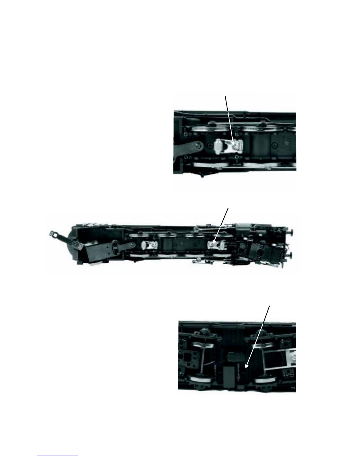
Installing/Removing 3-Rail Pickup Rollers
Both 2-Rail and 3-Rail versions of
this locomotive can be configured
to operate on either 2-rail or 3-rail
track by removing or adding the
center rail pickups. 3-rail track
operation requires the pickups,
2-rail track operation does not.
The pickups are factory installed on
3-rail versions and packaged
separately in the locomotive box for
2-rail versions. Each pickup roller
installs with a single Phillips screw
seen in Figure 1.
Once you have configured the
engine for 2-rail or 3-rail operation,
you must manually select the
power input switch located in the
first tender top hatch for 2-rail
operation as seen in Figure 2.
Configuring for 2-Rail or 3-Rail Power Input
Figure 1: 3-Rail Pickups installed with a single Phillips Screw
Figure 2: Selecting 2-rail or 3-rail power input setting
2-Rail/3-Rail Switch
Phillips Screw
Phillips Screw
Premier 2-4-1A Mountain Steam Locomotive
3
DCS or DCC
If you are operating with command control you must set the selector switch to DCC for
DCC operation and DCS for DCS operation. Refer to page to see and learn about the
differences.
9
CAUTION:
Do not apply DCS signals and DCC signals to the same track simultaneously. The
signals are not compatible, mixing the DCS and DCC signals will damage the DCS
TIU unit.
DCS/DCC Switch
Figure 3:
DCS/DCC Switch
Premier 2-4-1A Mountain Steam Locomotive
4
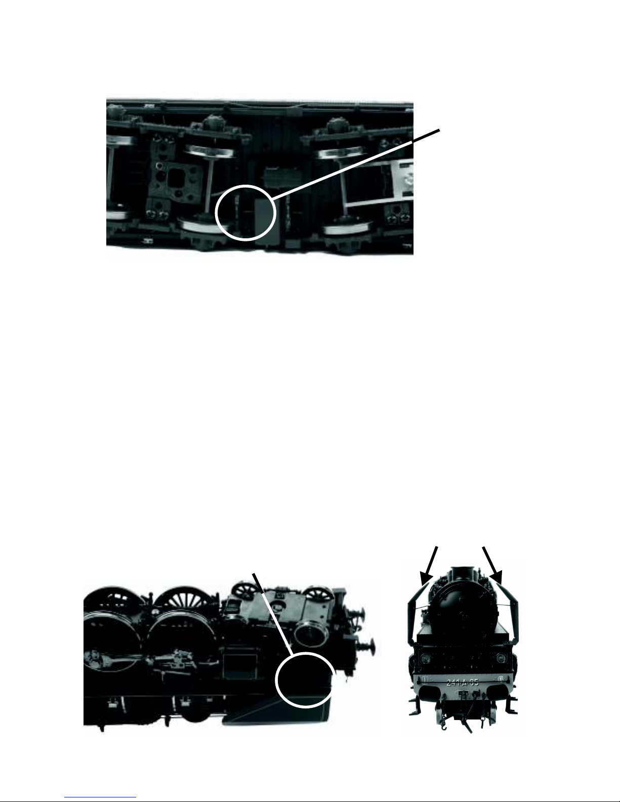
Smoke Deflector Installation
The smoke deflectors are supplied in the package to prevent damage in shipping.
The smoke deflectors are marked L for the left side and R for the right side and are
easily installed with the supplied screws.
Insert the tab at the end of the support into the slot on the inner side of the smoke
deflector. Then align the holes in the base of the smoke deflector with the holes in the
running boards and insert the supplied screws from the under side of the running
board.
Location of screws
Smoke Deflectors
Coupler Systems
The Chapelon Pacific is packaged with 4
different coupling systems.
- European Fine Scale Coupler System
- MTH Remote-Controlled Proto Coupler
- Ace Trains compatible coupler
- Kadee type mounting bracket (Scale
Wheel versions only)(Couplers not provided)
All versions have the European Fine Scale
Coupler mounted on the front pilot beam.
Two tender pilot beams are provided. One is for use with the European Fine Scale
Coupler. The other pilot is used for the MTH Proto-Coupler, The ACE Trains type
coupler and the Kadee type coupler
All versions have an ACE Trains type coupler in the packaging that can mounted on
the tender truck.
The Scale Wheeled Tender has the European Fine Scale Coupler mounted on the
rear pilot beam. An M.T.H. Remote-Control Proto Coupler is provided in the
nd
packaging along with the an 2 Pilot Beam that is required to install the coil coupler.
In addition a mounting bracket is supplied for mounting a Kadee style coupler on
the tender.
The Hi-rail Wheeled Tender has an MTH Remote Controlled Proto Coupler
mounted on the rear tender truck. A European Fine Scale Coupler is provided in the
packaging along with correct pilot beam need to mount the European Fine Scale
Coupler.
To remove or install the MTH Remote-Controlled Proto Coupler the tender shell
must be removed to unplug or connect the coupler control wires to the Proto
Coupler.
Premier 2-4-1A Mountain Steam Locomotive
5
Coupling Systems
European Fine Scale Coupler
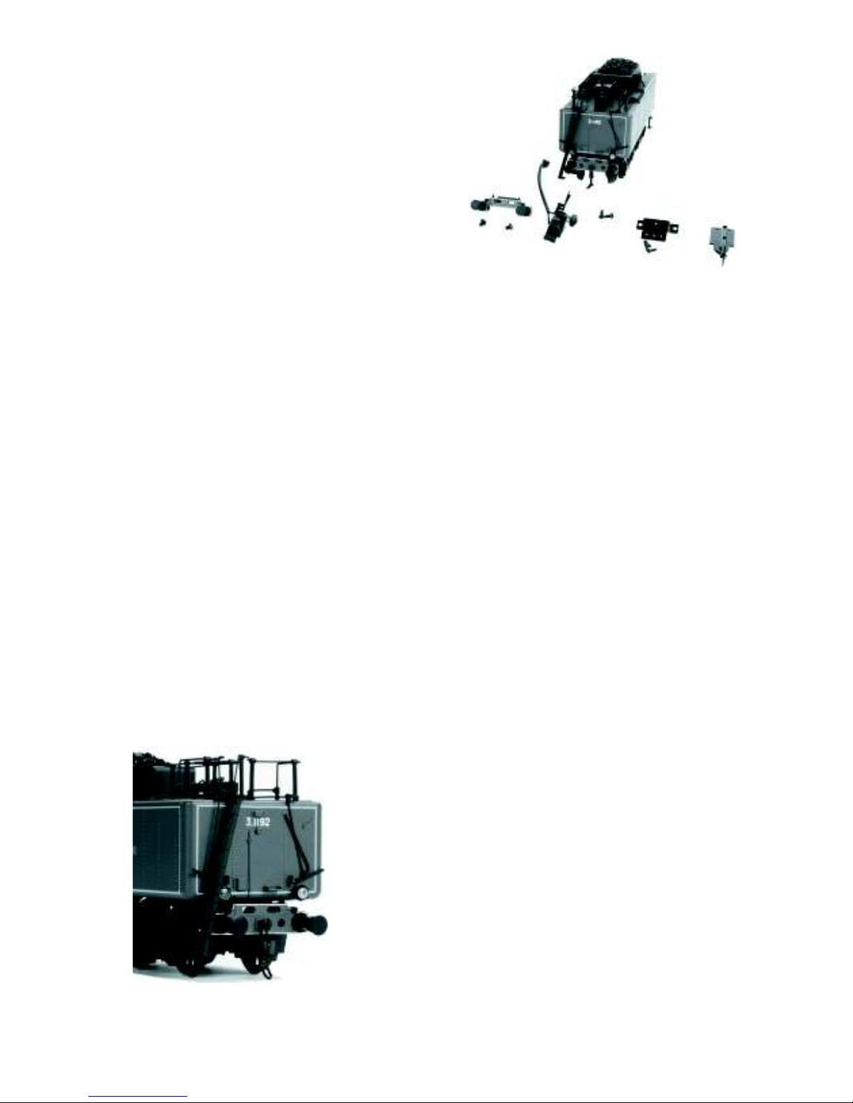
Proto-Coupler Installation
Owners of 2-rail models who intend to run this locomotive on a 3-rail layout may
wish to use the M.T.H. Proto-Coupler so that they may enjoy the remote
uncoupling anywhere on the layout.
A Proto-Coupler and the necessary mounting hardware are included in the
packaging with each 2-rail locomotive. The wire harness in the tender is prewired
with a plug-in connection for the Proto-Coupler.
To install the Proto-Coupler on a 2-rail tender, follow the step by step instruction
listed below.
- First remove the Fine Scale European Coupler and pilot beam from the bottom
of the tender chassis.
- Install the optional pilot beam with no coupler installed
- Next remove the shell from the tender by removing the 4 body screws and then
unplug the wire harness between the shell and the chassis.
Remote Controlled Proto-Coupler
Optional Tender Couplers
Ace Trains Coupler
Kadee® Coupler Bracket Installed
Premier 2-4-1A Mountain Steam Locomotive
6

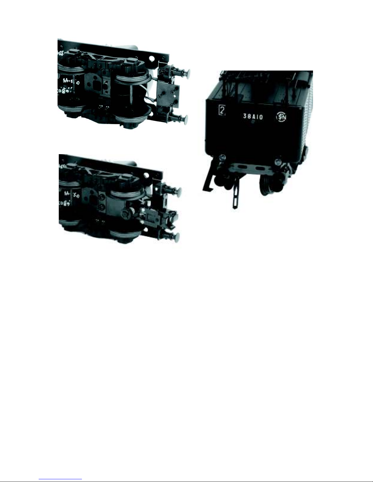
- Attach the proto-coupler to rear tender truck as shown.
- Plug the Proto-Coupler to the black connector provided.
- Reconnect the wire harness between the tender chassis and the tender shell.
- Reattach the tender shell. Remember that the front step piece goes under the
chassis.
When power is applied to the engine the Proto-Coupler can be operated anywhere
on the layout. To operate the coupler in the command mode, press the rear coupler
button on the DCS remote each time you want the coupler to open.
To operate the coupler in the conventional mode, the coupler can be opened by
quickly pressing the Bell Button and Horn Button (1 Bell and 3 Horns) on a Z4000 or compatible Toy Train Transformer. Refer to the Proto-Sound 3.0
Operating Instructions on page 19.
Premier 2-4-1A Mountain Steam Locomotive
7
Your MTH steam engine is equipped with a tetherless drawbar. There is no unsightly
cable or box showing between the engine and the tender to detract from the appearance
of the model. The electrical connections pass through conductors in the drawbar, so it is
important that the connector be properly inserted. The connector is fixed to the rear end
of the drawbar. The mating connector is attached to a swivel connection on the front of
the tender frame. The drawbar is connected to the engine chassis with a screw and
should not need any attention.
In order to mate the connectors of the drawbar and the tender, place the engine and the
tender on the track. Position the tender over the drawbar connector and insert the
drawbar pin on the swivel connector into the hole in the drawbar.
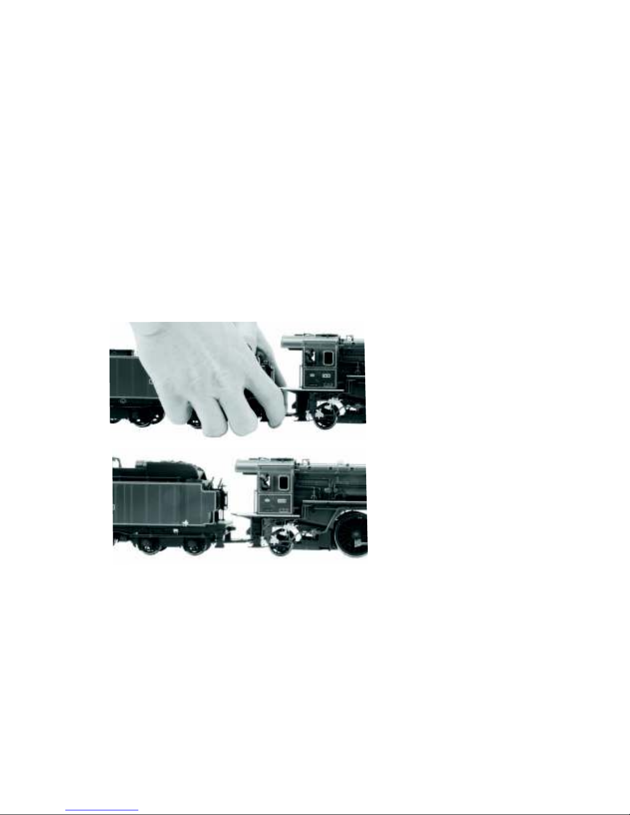
Now grasp the tender with both hands as shown below (in Fig. 8) and place a finger on
each side of the drawbar near the connector. Now using your fingers, push the
connectors together. The connector will make a slight click when it is properly
seated(in Fig. 9). At this point you are ready to begin operating your engine.
Placing The Engine On The Track
To disconnect the engine and tender apply downward pressure near the tender until the
connectors separate.
The drawbar is able to withstand a 90 degree twist such as might be experienced in a
derailment where the engine or the tender would turn over and the other unit would
remain upright.
If the drawbar is not properly connected your engine may exhibit erratic or no
operation. If this happens turn off the track power and make sure that the drawbar
connectors are properly seated. Then reapply power to the track and continue
operation.
Fig. 8: Pushing Connectors Together
Fig. 9: Connected Engine and Tender
Premier 2-4-1A Mountain Steam Locomotive
8

PS 3.0 Enhancements
®
Here are some of the exciting changes incorporated into your new MTH Proto-Sound
3.0 Locomotives. More advanced features such as Custom Speed Tables and Advanced
Consisting can be found in the DCC section of this manual.
Conventional (Analog) AC/DC Start-up/Shut-down
Your new MTH PS3.0-equipped locomotive no longer has batteries. It uses Super
Capacitors to hold the engine board alive for a short time when you shut off or interrupt
track power. Because of this, when you first apply track power to your PS3.0-equipped
O Gauge engine, you will notice the headlight comes on but nothing else. This is
perfectly normal. The capacitors are charging up during this time. The wait time
depends upon how long it’s been since you last applied power to the engine. Typically
it will take 1-15 seconds to fully charge. NOTE: The 1-15 second charging wait time
ONLY applies to conventional AC track power.
Once the headlight shuts off, the engine will play its start-up sounds and all the lights
will come back on, simultaneously. Smoke too if you have it turned on.
The capacitors hold enough charge to play the full shut-down sounds. Also, the
capacitors allow you to operate your engine in conventional mode just like you would
any other conventionally-controlled engine. Finally, because there are no batteries, you
will notice there is no external charge jack on the engine.
DCS/DCC Switch
Your MTH PS3.0-equipped engine has a DCS/DCC selector switch (located on the
underside of the tender in steam engines). To operate the engine in DCS mode, ensure
the switch is set to DCS. If you wish to run the engine in DCC mode, ensure the switch
is set to DCC.
If you inadvertently leave the switch in DCC it won’t hurt anything, you just won’t be
able to communicate with your engine with your DCS system. Likewise, if you leave
the switch in DCS and try to operate the engine under DCC you may notice a humming
coming from your engine and you will likely notice that your DCC system’s overload
light will be on.
Programming Track (for DCC operation)
Your MTH PS3.0-equipped O Gauge engine can function on Programming Track
outputs from DCC systems. Most DCC systems can support the current requirements of
the engine as long as it’s not started up. If you plan on powering up the MTH engine on
your programming track, you may want to consider a DCC Programming Track
Booster.
Premier 2-4-1A Mountain Steam Locomotive
9

Loading Tender and/or Boiler Firmware
Your new MTH PS3.0-equipped O-Gauge engine affords you the ability to load DSP
firmware. Additionally, in steam engines you can load boiler firmware. Loader version
2.20 or later will allow you to do this. Please refer to the Loader program’s instructions
for more details. So, as MTH releases new features or updates you will be able to take
full advantage without having to ship your favorite engine anywhere. All new updates
are available on our website. MTH will make announcements as they are available. Not
all updates will apply to all engines. NOTE: Requires a TIU w/ version 4.20 or later
firmware, and requires loader version 2.20 or later.
LED Lighting
Gone are the incandescent bulbs. Your new PS3.0-equipped engine has LED lighting.
MTH uses various colored LEDs to simulate the correct lighting on your engines from
the warm, yellow-orange colored light coming out of an old lantern on your favorite
steam engine to the high-intensity halogen lamp on the latest modern diesels, LED's
allow for various, correct colors. Also, they require less power and do not emit as much
heat as incandescent bulbs.
Modes of Operation
®
There are 4 options for operating your MTH Proto-Sound 3.0-equipped engine;
-Conventional AC
-Conventional DC
-DCS - MTH Digital Command System
-DCC
When the locomotive is placed on the track and power is applied to the track the
locomotive will detect the type of control system being used and respond accordingly.
Below is an overview of the 4 different systems.
NOTE: You’ll need to have the DCC/DCS switch set correctly if your using one of
those two modes.
Conventional AC Operation
When using conventional AC power, the engine will respond to changes in track
voltage. An increase in track voltage will increase the locomotive speed and a reduction
in track voltage will reduce the engine speed.
A short interruption (approximately 1 to 2 seconds) in the track voltage will cause the
engine to cycle in the sequence for each track voltage interruption (neutral – forward –
neutral – reverse)
Premier 2-4-1A Mountain Steam Locomotive
10

When power is first applied to the track, the locomotive will be silent for a few seconds
until the super capacitors are charged (The super capacitors provide power to the sound
system during direction changes or intermittent drops in track power due to dirty track
on or switches, when operating in conventional mode). When the super capacitors are
charged, all the lights will come on and the engine sounds will start up. There should be
no movement, as the engine is in neutral. Causing a short interruption of track power
by using the direction button on the transformer, or by turning the throttle off and then
back on again, will change the sequence to the forward state. Then increasing the
throttle will begin to move the engine forward, and speed will increase as the throttle is
advanced.
If there is another interruption in track power the sequence will change to the neutral
position again. The engine will remain in the neutral state until there is another
interruption in track power. The next interruption in track power will move the
sequence to the reverse state. The engine will now move in the reverse direction. If the
power interruption was accomplished by using the direction button and the throttle
position was not changed, the engine will run in the reverse direction at the same speed
that it was traveling in the forward position.
Subsequent interruptions in track power of 1-2 seconds will continue the sequence
rotation. If you happen to interrupt track power for longer than about 2 seconds, the
engine will begin its shut down sounds. If this occurs you can cycle the direction
sequence again to get back to the direction you wish to move and once the engine starts
moving its shut down sounds will stop playing.
In conventional AC operation the whistle sound, the bell sound, PFA sounds and other
operational functions can be accessed if your transformer has a horn/whistle button and
a bell button. By using combinations of button presses, different commands besides
blowing the whistle and ringing the bell can be initiated.
See page 14 for activating Conventional AC Features
Conventional DC Operation
Your MTH locomotive will operate on conventional DC track voltage also. However,
functions such as blowing the whistle, ringing the bell, and the PSA sounds cannot be
initiated in conventional DC. Only the steam chuffing sounds with synchronized
puffing smoke, squealing brake sounds, and idle sounds will function.
Operation of your MTH Proto-Sound 3.0 engine in conventional DC is very similar to
operating a conventional AC engine. As you increase track voltage, engine speed
increases.
As the track voltage is decreased, engine speed is decreased. When track voltage
polarity is reversed using the direction button on the power pack, the engine will run in
the opposite direction. The electronics in your MTH Proto-Sound 3.0 locomotive are
designed to slowly change direction without a need to change the throttle, if you so
desire.
Premier 2-4-1A Mountain Steam Locomotive
11

Just change the polarity switch on your DC power pack and the engine will gradually
come to a stop and then automatically begin traveling in the opposite direction. The
speed will build up to the same speed that the engine was going in the previous direction.
When power is first applied to the locomotive, the engine’s sounds will start up when the
track voltage reaches about 8 VDC. To get your locomotive moving, after the startup
sounds have finished and the locomotive is idling, slowly increase the track voltage until
the locomotive is traveling at the desired speed.
DCC - Digital Command Control
DCC is a popular digital command scheme wherein the track power is also a digital
control signal. That is, using a DCC controller, you can communicate with multiple
engines and have all of them moving at different speeds and in varying directions
on the same track at the same time. The power/command signal remains constant
and engines are commanded to perform as desired. Your MTH PS3.0-equipped
engine has the ability to decode and respond to these DCC commands. This allows
you to mix and match MTH PS3—equipped engines as well as operate them with
any other manufacturer's DCC-decoder equipped engine. The best part about your
MTH PS3.0-equipped engine is that the decoder is built right in. No need to
remove the hood and install speakers or boards. It's all done for you at the factory.
Each PS3.0-equipped engine has a full complement of lights, sounds, smoke (if
equipped). Just set the model on the rails, apply DCC power and hit F3 on your
DCC handheld controller and you're off and running.
Basic DCC Operation:
Your MTH PS3.0-equipped engine takes full advantage of DCC's capabilities.
Below are the basic commands you'll want to know to get started running quickly.
Please refer to the Advanced DCC Operation section of the manual if you want to
dig into the full capability of DCC.
Each engine type may have a slightly different F Function list. This depends upon
whether it's steam, diesel, or electric and whether it has smoke or not. Please refer
to the table of Default CV Values for your particular engine's F Functions.
A note about enabling/disabling F Functions in DCC - Depending upon the DCC
system you have you may need to toggle a particular F Function on then off to
actually get it to enable. Some DCC systems do this for you automatically and
others allow you to set particular F Function buttons to either be set for momentary
or toggle. Please refer to your DCC control station manufacturer's manual for more
information on how they handle F Function buttons.
Premier 2-4-1A Mountain Steam Locomotive
12

Your MTH PS3.0-equipped engine's default short address is 3. So all you
have to do is power up your DCC system and call up Locomotive 3 to begin.
Start-Up/Shut-Down
F3 – Pressing this twice (toggle on then off) will start up your engine. When you
apply DCC power your MTH PS3.0-equipped engine will remain dark and quiet.
Since you likely don't want to run the engine this way, simply press F3 twice to
start your engine. The lights, sound and smoke (if equipped) will come on.
Note – You are actually able to move the engine in DCC without starting it up.
Just increasing the throttle will cause the engine to move. In order for F3 to
function correctly the engine must NOT be moving
To shut your engine down, press the F3 button twice. This will play the shut
down sounds and then turn the lights and smoke and sounds off. As long as there
is DCC power still on the track the engine can be started up again by pressing the
F3 button twice.
Bell/Whistle (Horn)
F1 – Bell. To activate the Bell press F1. To deactivate it, hit F1 again
F2 – Whistle (Horn). To activate the Whistle/Horn, press F2. To shut it off either
let off the F2 button or press and release it
PFA
F4 – PFA. PFA in MTH lingo stands for Passenger/Freight Announcements. Your
engine is pre-programmed for the appropriate type of sounds based upon the type
of service the real-life engine used in daily operation.
There are five sound sequences or segments in the PFA feature. Each segment is
advanced by you, the operator. You hit the Direction button on the DCC
controller to let the engine know you want it to advance. In most PFA sequences
there is a minimum wait time of about 10 seconds before it will advance. So,
here is how a typical PFA sequence operates:
1. Press the F4 button twice (toggle F4 on then off) to start the PFA
sequence on the engine. You'll hear “Now arriving…”
2. Press the F4 button twice (toggle F4 on then off) again to stop the engine
at the station. It is recommended to do it this way rather than bring the engine to a
stop with the throttle since PFA allows automatic departure (movement) of the
engine after the last F4 toggle. You'll hear the engine sounds switch from the cab
to the station with all the ambient station sounds you'd hear in the real thing
Premier 2-4-1A Mountain Steam Locomotive
13

3. Press the F4 button twice (toggle F4 on then off) again to advance the
sequence. You'll hear “Now boarding…”
4. Press the F4 button twice (toggle F4 on then off) again to advance the
sequence. You'll hear “Now departing…”
5. Press the F4 button twice (toggle F4 on then off) the last time to advance
the sequence. You'll hear “All aboard…” the engine sounds will switch over to
the cab again and the engine will pull away at the same speed it entered the
station. For a few seconds the bell will ring as it's departing the station
Note – In order to maximize the realism, we recommend that you reduce the
engine's speed to a slow pace just prior to hitting the F4 button the first time (to
activate PFA)
Lights
F5 – Lights. This toggles all your lights (except the headlight) on and off
Master Volume
F6 – Master Volume. There are 10 volume levels. Pressing F6 twice (toggling on
then off) raises the Master Volume one level. The Master Volume loops. That is,
if you go past the 10th level it will loop back around to the 1st or lowest volume
level.
Couplers
Your MTH PS3.0-equipped engine comes with remotely controlled ProtoCouplers. They can be fired using your DCC handheld.
F7 – Rear Coupler. Pressing F7 twice (toggling on then off) will fire your Rear
Coupler
Forward/Reverse Signal
Just like a real engine, you can announce the direction of travel using your DCC
handheld and F9 and F10.
F8 – Forward Signal. Pressing F8 twice (toggling on then off) will sound the
Forward Signal. This is two whistle/horn blasts
F9 – Reverse Signal. Pressing F9 twice (toggling on then off) will sound the
Reverse Signal. This is three whistle/horn blasts
Premier 2-4-1A Mountain Steam Locomotive
14
 Loading...