

MTHTrains M50, L50 Instruction Manual
Section M50 • L50
Page 501
Dated
October 2010
97-4624-01-588
VERTICAL CLOSE COUPLED

Page 502
1.
VERTICAL CLOSE COUPLED PUMPS
Storage
C.
Application Considerations
When properly installed and given
operate satisfactorily for many years.
pressures expected in a regenerative
turbine pump, close running clearances
are used to reduce internal losses.
Abrasive particles, even microscopic
ones, in high enough concentrations,
can open up the close clearances
between internal components. For
critical services it is recommended that
you keep an identical pump for stand-
by use.
1A Inspection of Equipment
shipment, inspect the equipment for
damage or missing components.
Check the shipping manifest and
Transportation Company’s local agent.
material before discarding. Parts or
accessories are sometimes wrapped
individually or fastened to the skid.
shipment in a safe place where they
will be available to those who will be
using them for installation and service.
1B Storage
it should be inspected as described
in 1A, recrated and stored in a dry
location. Standard shipping containers
are not suitable for outdoor storage.
to cover the pump’s exterior surface
with oil or other rust inhibiting coating.
All units are tested at the factory with
a water/corrosion inhibitor solution,
some of which will remain inside the
pump upon receipt. If units are fl ushed
out prior to storage, this inhibitor will
be removed and proper care must be
taken to prevent product deterioration
from improper storage.
corrosion inhibiting protective fl uid
should be added to the internal pump
cavities. Fluids used in the pump
should be selected for compatibility
with pump materials. This is very
important when optional seal and
gasket materials have been used.
should also be used. Caps alone are
not suffi cient protection
1C Placing Stored Pumps Into
Service
Special care must be taken when
placing stored pumps into service.
the inside with a process compatible
fl uid. Try to turn the pump using the
coupling or shaft. On close-coupled
units, access to the shaft is between
the pump and motor. A vise grip or
other plier type gripping device may
be used directly on the shaft. Applying
torque to the motor fan blades is not
break loose immediately, fi ll the pump
with a process compatible fl uid and try
again in a few hours.
understanding of which are the bolts
used to clamp the entire assembly
together, loosen each of them exactly
three full turns. After fi lling the pump
with water again, up to 50 foot pounds
of torque may be applied to the
coupling or shaft without fear of ruining
the impeller vanes. It should begin to
turn well before this force is reached.
Continue turning the pump while the
various fasteners are returned to their
original positions.
in Section 5 to determine the cause of
the problem.
1D Application Considerations
All electrical equipment and wiring
should conform to local and National
manufacturer’s instructions for
connecting the motor. Note the correct
assembly. Make sure the motor
While it is reasonable to assume that
good judgement has been used in
selecting all the materials in the pump
for compatibility with process fl uids,
actual conditions sometimes vary
from original specifi cations. Also,
typical material selection charts do not
consider all the temperature, pressure,
and fl uid variables. The customer’s
engineer should be consulted for fi nal
judgement on the best materials for
critical process applications.
The fi rst valve to be considered
for a regenerative turbine pumping
system might be a pressure relief
valve. Because this type of pump
has a horsepower requirement similar
to that of a positive displacement
pump (constantly rising hp along with
pressure increases) a relief valve can
be effectively used to limit horsepower.
This is helpful when a non-overloading
motor is specifi ed. It can be of
critical importance if the system
fl ow rate can vary widely. There
are almost no circumstances where
a fl ow modulating valve will work
successfully in a regenerative turbine
pumping system. The steep pumping
characteristic, typical of these pumps,
produces very large pressure changes
with small variations in fl ow rate. As
a result, the modulating fl ow from the
valve introduces sharp pressure shock
waves that shorten pump life and
may cause damage to other pieces of
equipment in the system.
A swing check valve is recommended
in the suction line even when the
pump inlet is only slightly higher than
the fl uid source. It should be the same
size as the pump inlet or sized based
on reasonable fl uid friction losses.
A foot valve is recommended when
lifting fl uid from a sump. This will
save wear and tear on any pump,
even those equipped with self priming
capability.
A Y-Strainer is recommended
immediately ahead of the pump on
any newly constructed system. This
is advisable due to the probability
that foreign material large enough to
damage pump clearances may remain
even though the piping has been
fl ushed.

entrance velocity in the pump. If a
pump requires more energy (or NPSH)
than is available at a given capacity,
the pressure at the inlet will fall below
the vapor pressure of the pumped
liquid and loss of performance will
s
= Pressure in the suction vessel in
vp
= Vapor pressure of the pumped
fl uid in PSIA.
s
= Static height of the pumped fl uid
above (+) or below (-) the centerline of
the pump in feet.
= All friction losses from the vessel
= All friction losses from the vessel
to the pump in feet.
s
s
and P
vp
are
equal. This item then becomes zero
and can be omitted from the equation.
produce a high pitched whine that
increases in intensity as the differential
pressure produced in the pump
increases. While high frequency
sound is attenuated more easily than
lower frequencies, piping structures
and the fl uids in them readily transmit
noise. Motors, bearings, and other
and sometimes create objectionable
harmonics.
Adequate support for the inlet and
discharge piping is important for noise
When ambient temperatures drop
below the freezing point of the fl uid
in a pump, consideration should be
given to heating, insulating, or draining
the pump. If you choose to drain the
pump, and it will only be for a short
period, fi rst remove the drain plugs,
Page 503
Ps - P
vp
sp. gr.
Valves in the outlet piping of a
always be open as far as possible
when the pump is started. This will
and motor. Never start the pump with
the discharge valve closed.
starting any pumping system. Without
some fl uid in the pump, it can gall
and lock up the impellers. Violent
pump failure will result from continued
operation with the inlet valve closed.
equipment is used or not, always fi ll the
pump and vent it of air before starting,
for best seal and pump life. Under
most circumstances, regenerative
turbine pumps can be made to self-
prime as long as a
small amount of
fl uid can be recirculated through the
impeller and the fl uid doesn’t heat up
noticeably.
The NPSH required varies with every
size and capacity of pump. The NPSH
from the performance curves or from
your MTH representative.
greater than that required by the pump,
it must be increased or a different
pump selected. The usual method for
increasing NPSH is to raise the static
head on the pump inlet, (H
s
).
positive suction head” above the
vapor pressure of the pumped liquid
available at the centerline of the
pump. It should always be given in
feet of pumped liquid. The NPSH is
actually a measurement of the amount
of energy available in the pumped
liquid to produce the required absolute
then drain the inlet and outlet lines.
Carefully blow out the pump with
compressed air to clear all internal
cavities of fl uid.
1E Recommended Spare Parts
installation, with two identical pumping
units in parallel, is the safest and many
times the most cost effective choice.
standby pump, ready for installation is
advised.
Special pricing and new pump
warranty is offered for factory
short as one or two days for standard
models.
- only the mechanical seals and a
complete set of “O” ring gaskets are
components show wear, they are
available from stock at the factory.
gaskets, impeller, and channel rings.
components required for servicing,
plus bearings, shaft, and drive keys
for fl exible coupled pumps, should
be obtained. A factory rebuild
should be considered whenever your
disassembly indicates rebuilding is
necessary, as this is usually more
economical.
The factory recommendation for
spare parts are all of those listed for
the exploded view drawings for each
individual type of pump.
2.
CLOSE COUPLED PUMPS
C.
Alignment
Typical Installation
equipment is installed properly and
to obtain reliable pump operation,
it is recommended that only
experienced, qualifi ed erecting
engineers undertake this task. Read
the instructions thoroughly before
beginning.
2A Location
Page 504
The fi rst consideration for locating
a pump is elevation. The lowest
possible elevation using the shortest
possible suction piping is usually
the best. Questions regarding
possible locations should be resolved
by making inlet head calculations
including all friction losses. The one
producing the highest inlet pressure
should be selected. One reason for
this precaution is that, the greater
the inlet pressure, the less likelihood
of NPSH problems. Also, a fl ooded
suction is particularly helpful on
start-up when the seals or the entire
pump can be ruined because it is not
properly primed and purged of air.
A dry, easily accessible location
is also important. Allow ample
clearance around the unit for free
air circulation. If a dry location is
not available, the pump can be
mounted on a foundation, above
the fl oor. Specify motor enclosure,
pump materials, or coatings to suit
the worst conditions expected.
easily inspected and serviced during
operation. Suffi cient head room
should be provided, particularly when
lifting devices will be used for heavier
assemblies.
2B Foundation
enough to maintain alignment of
the unit. The pump foundation is
used as a support for the baseplate
to maintain alignment of the unit. If
the baseplate is to be grouted to the
foundation, it is only necessary to
embed the edges. It is unnecessary
to completely fi ll under the baseplate.
foundation until it has been properly
aligned.
The foundation must be a permanent
material of suffi cient mass to absorb
4. Check the baseplate for
distortion:
a. Place a straightedge along
the baseplate to determine if
it is distorted.
b. Adjust the shims until the
baseplate is not distorted.
5. Use a section of pipe to
determine if the inlet and
discharge openings are vertical
and located properly.
6. Correct the positions, if
necessary, by adjusting the
shims.
2D Alignment
Although fl exible coupled pumps
are carefully aligned prior to crating
and shipping, it is very likely that
strains imposed during transit have
altered the alignment. Complete
the following steps after the unit has
been placed on the foundation and
leveled.
To check the PARALLEL alignment:
(Refer to Figure 2-4)
two coupling fl anges.
2. Measure the maximum offset
(A), Figure 2-4, at various points
Figure 2-1
Figure 2-2
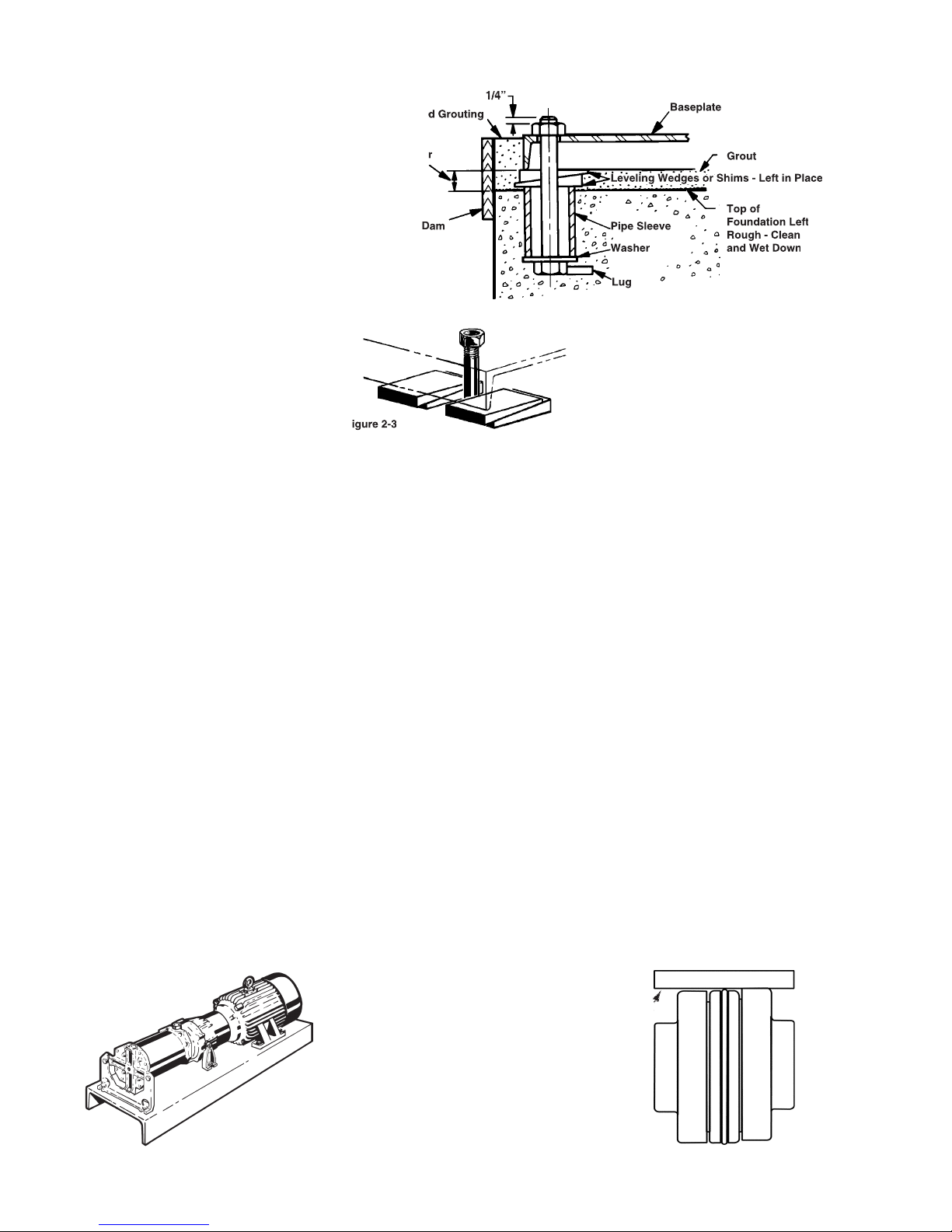
Foundation
1/4”
Finished Grouting
3/4” to 1 1/2”
Allowance for
Grout
Dam
Baseplate
Grout
Leveling Wedges or Shims - Left in Place
Pipe Sleeve
Washer
Lug
Top of
Foundation Left
Rough - Clean
and Wet Down
Figure 2-3
all normal vibrations. Locate the
foundation bolts using a layout or
template in relation to the suction
and discharge piping. If concrete is
being used, foundation bolts of the
specifi ed size can be enclosed in a
pipe sleeve two to three diameters
larger than the bolts to compensate
for minor variations in alignment.
Close coupled pumps can be
mounted on a steel base prior to
installation or mounted directly to
the foundation. Place shims under
one or more of the motor feet so
that strain and distortion will not
tightened.
2C Leveling (Flexible Coupled
and motor mounted on the baseplate:
2. Disconnect the coupling halves.
alignment procedures have been
completed.
3. Support the baseplate on metal
shims or wedges having a small
taper. (Refer to Figure 2-2)
a. Place shims close to the
foundation bolts. (Refer to
b. Also place shims close to
where the greatest weight is
located.
Figure 2-4
A

around the periphery of the
coupling. DO NOT rotate the
coupling.
3. If the maximum offset exceeds
the Parallel dimension in Chart 1
for your sleeve size, loosen the
motor or pump and place thin
metal shims under the motor
or pump feet until the offset is
corrected.
CHART 1
COUPLING TYPES JE, J, S
MAX. RPM & ALLOWABLE MISALIGNMENT
SLEEVE
SIZE
MAXIMUM
ANGULAR
B-C
3
9200
.010
.035
7600
.010
.043
5
7600
.015
.056
6
6000
.015
.070
5250
.020
.081
8
4500
.020
.094
4. Torque down the motor or pump.
5. Recheck alignment.
To check the ANGULAR alignment:
(Refer to Figure 2-5)
measure from the outside of one
fl ange to the outside of the other
at intervals around the periphery
of the coupling. DO NOT rotate
the coupling.
Figure 2-5
C
Page 505
2. Determine the maximum (B) and
minimum (C) dimensions.
3. If the difference between the
maximum and minimum exceeds
the Angular dimension
in Chart 1
for your sleeve size, loosen the
motor or pump and place thin
metal shims under the motor or
pump feet until the misalignment
is corrected.
4. Torque down the motor or pump.
5. Recheck the parallel alignment
above.
is great, this is an indication of
baseplate distortion and must be
corrected fi rst, refer to 2C Leveling.
After all leveling and alignment
operations have been completed,
piping can begin. After the piping has
been completed, refer to 2E1 Piping
Alignment. Alignment of the unit
must be rechecked to make certain
that no piping strains are causing
distortion. After approximately
two weeks of operation, check the
alignment again to make sure that
temperature changes, piping strain,
or foundation variations have not
caused misalignment. If alignment
has been maintained over this period,
the pump and motor can be doweled
to the baseplate.
2E Piping
2E1 Alignment
up and not forced into place. It is
at the pump. If the lines are ended at
the pump, particularly if the last piece
is cut a little too short or long, the
pump will be forced to meet the pipe
and strain or distortion will result.
2E2 Piping Support
piping. Other means such as
pipe hangers and pipe supports
should be used to carry piping to
avoid misalignment and distortion.
Consideration should be given to
thermally induced expansion and
contraction, particularly in long runs
of straight pipe.
2E3 Piping Size
pipe sizes should be equal to or
larger than those of the pump.
3.
CLOSE COUPLED PUMPS
Rotation
Inlet and Outlet Locations
C.
Foreign Material
Electrical
Adjustments
Cooling Water
G.
Priming
Starting
Stopping
3A Rotation
The standard direction of rotation
for the pump is right-handed, or
clockwise when looking at the motor
end of the pump. A rotation arrow,
pump to indicate the correct direction
of rotation.
Operating the pump in reverse will
cause substantial performance
variations and can damage the
pump.
Always confi rm correct motor rotation
prior to connection of the coupling.
2. Observe rotation as the unit
comes to a stop.
3. Rotation should be in the
direction of the arrow.
direction:
three-phase motor.
2. On a single-phase motor,
change the leads as indicated on
the connection box cover. Some
single-phase motors may not be
3B Inlet and Outlet Locations
(Refer to Figure 3-1)
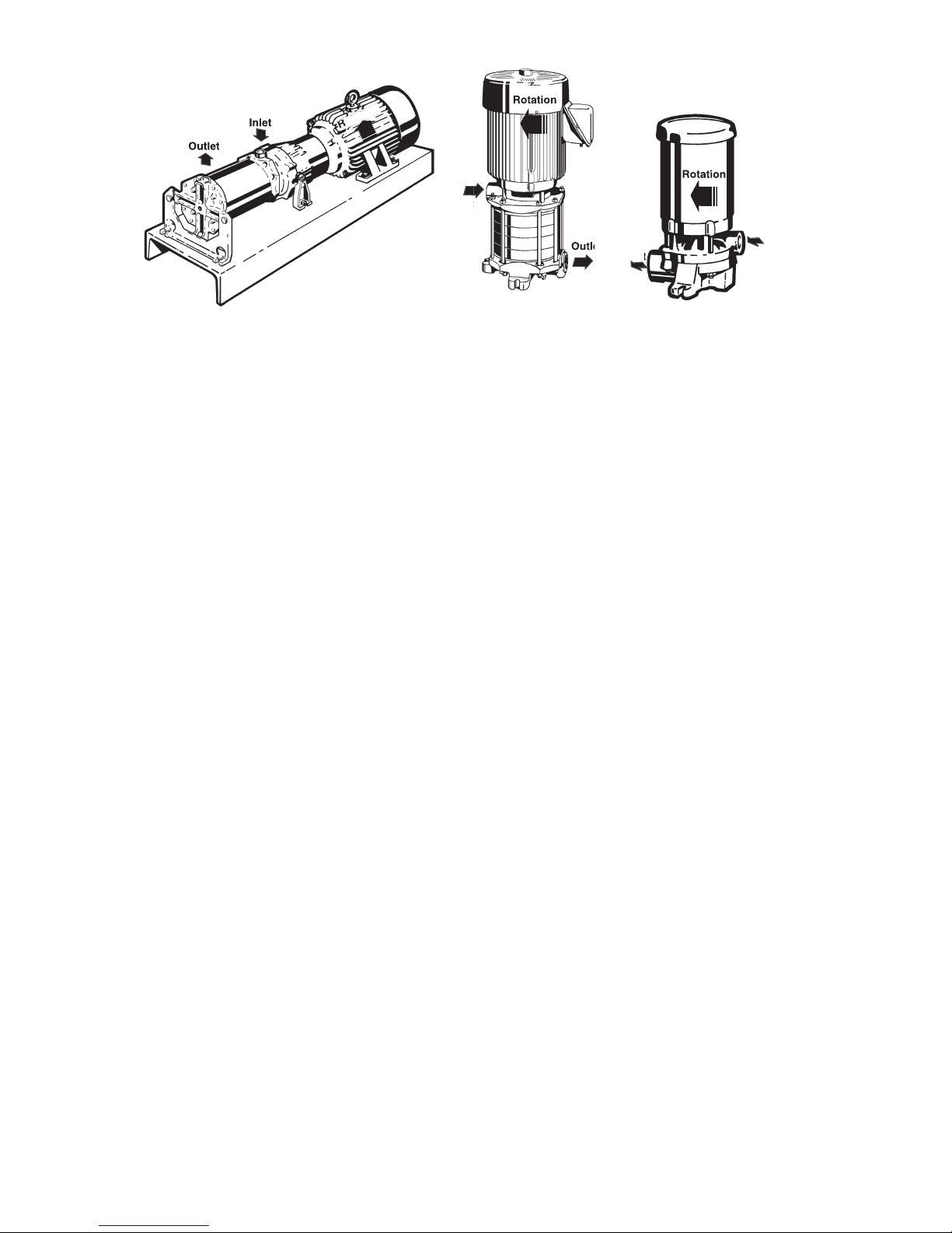
Page 506
The pump inlet is located on the end
nearest the motor, except on Model
form the motor. The discharge or
“outlet” can be on the top, side, or
bottom depending on the model and
construction of the pump. Normal
discharge position is located on
top
in horizontal confi gurations,
or in line with vertically mounted
confi gurations.
3C Foreign Material
All regenerative turbine pumps have
close running clearances in order
to maintain effi ciency. Take extra
precautions to insure that no foreign
material larger than 25 microns
or .001 inches is allowed to pass
through the pump. Even particles
of this size can damage the pump
if allowed to circulate continuously.
designed for slurries.
other material found in new piping
systems will bend the impeller
vanes and can sometimes lock up
the pump. If a new pump does not
operate properly, the fi rst thing to
check for is damage from foreign
material.
3D Electrical
follow the appropriate local and
national electrical codes. Do
not make wiring alterations that
can affect motor rotation without
When
making electrical connections to motors
provided with threaded stud electrical
terminals, the recommended torque
should be 13-16 inch-lbs. Applying
torque in excess of this range may cause
damage.
3E Adjustments
advisable on new pumps other
than those required for installation.
not uncommon for the pump to be
diffi cult to turn over by hand after the
internal parts have been allowed to
dry out. New pumps from the factory
are tested using rust inhibitors to
help preclude this possibility. On site
system fl ushing may remove these
inhibitors and subject the pump to the
out. In this case, do the following:
2 hours prior to proceeding.
2. C3 Motors/P3 Bearing Frames
a. Using a 5/32” Allen wrench
inserted into the lock
collar setscrew (#15),
using the Allen wrench as
a handle rotate shaft to
verify there is not binding.
(DO NOT LOOSEN THE
SETSCREW)
b. Remove the Allen wrench.
c. Jog the pump momentarily
and observe there is no
binding or abnormal noise.
d. This should “break” the
impeller loose without
damage, unless foreign
material has entered the
pump.
3. C30 Motors/P30 Bearing Frames
a. Rotate the shaft to verify
there is no binding.
from the outlet cover and
insert a 3/8” Allen wrench
into the socket end of the
shaft, using the wrench as a
handle. If draining fl uid from
the pump is not practical,
use the coupling on fl ex-
coupled units to turn the
shaft. Otherwise, a vise grip
or other plier-type gripping
device may be used directly
on the shaft between the
pump and the motor.
b. Remove the Allen wrench or
pliers.
c. Replace the drain plug and
was drained.
d. Jog the pump momentarily
and observe there is no
binding or abnormal noise.
e. This should “break” the
impeller(s) loose without
damage, unless foreign
material has entered the
pump.
This procedure will fl ush residue from
the close fi tting impeller surfaces. If
not immediately successful, refer to
Section 1, 1C Placing Stored Pumps
fi tting surfaces inside these pumps,
it takes only microscopic residue to
produce resistance to rotation. Once
loosened, this material is quickly
dispersed and the impellers will
fi nd their hydraulic center. If these
procedures are followed carefully,
no damage will result from “breaking
loose” the impeller.
3F Cooling Water
When the pump is used to transfer
hot fl uids, consideration should be
given to cooling the seals and/or
selecting materials that will give
satisfactory seal life. The actual
temperature at the seal faces, the
most critical area, will always exceed
the surrounding fl uid temperature.
Figure 3-1
Outlet
Rotation
Inlet
Rotation
Inlet
Outlet
Outlet
Inlet

Page 507
4.
Figure 4-1
A.
Preliminary
Disassembly Vertical Single Stage
on C3 Motors
C.
Disassembly Multistage on C3
Disassembly Multistage on C30
Inspection of Components
Reassembly Vertical Single Stage
on C3 Motors
G.
Reassembly Multistage on C3
H.
Reassembly Multistage on C30
I.
Testing and Final Adjustments
4A Preliminary
the pump or motor, disconnect the
electrical power to the motor. If the
pump and motor are to be removed as
a unit, note the wiring confi guration,
using colored or numbered tape.
piping before unbolting the pump
and motor.
2. Unbolt the motor from the base
and remove the unit. All work on
the unit should be performed on
an elevated workbench whenever
possible.
The disassembly and reassembly
procedures are broken into eight
sections covering the following units:
— Disassembly Vertical Single
Stage on C3 Motors
C
— Disassembly Multistage on C3
— Disassembly Multistage on C30
— Reassembly Vertical Single Stage
on C3 Motors
— Reassembly Multistage on C3
G
— Reassembly Multistage on C30
4-4, 4-11, and 4-12, are provided
for referencing the numbers in the
following procedures, i.e. (#1), motor
bracket.
4B Disassembly Vertical Single
Stage on C3 Motors
The following tools and equipment are
needed for disassembly of C3 units.
2. 9/16” wrench or socket.
3. 5/32” hex wrench.
4. Penetrating oil.
5. 1” wood dowel (Approx. 6” long).
6. Thin blade screwdriver.
7. Two large blade screwdrivers.
To disassemble the pump:
the numbered parts in the procedures
below.
Air blown through the pump will
2. Remove the two (2) Nuts (#20)
and the two (2) 3/8” X 4” Bolts
(#19) from the Cover (#2). On
stainless steel models, remove the
four (4) Nuts (#20).
3. Remove the cover (#2). In some
cases light tapping with a plastic
or wooden mallet on the outside
diameter of the cover may be
motor bracket. Care should be
taken if a screwdriver is needed to
pry between the cover and motor
bracket. Damage to the “O” Ring
(#7) and/or impeller can result.
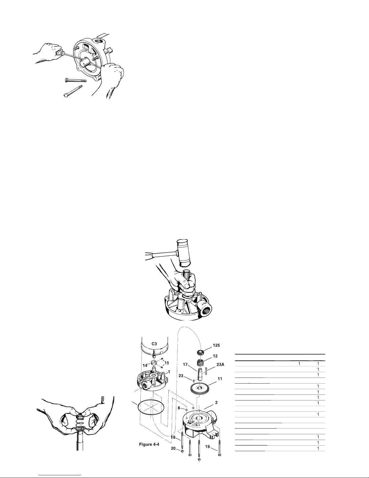
4. Remove the Impeller (#11). Refer
to Figure 4-1. The impeller is
a slip fi t and, under normal
conditions, can be removed by
gently tapping on the end of the
shaft sleeve with a mallet. Leave
the Impeller Key (#23) in place.
Striking the sleeve too hard could
damage the seat or rotating
element.
5. Using the 5/32” hex wrench,
loosen the Set Screws (#15) in
the Locking Collar (#14), located
on the shaft sleeve between the
motor bracket and the motor face.
3G Priming
unless they are completely fi lled
with liquid. Damage to parts of the
pump that depend on liquid for their
lubrication can occur. Impellers can
seize quickly when a pump is run dry.
Without lubrication, seal faces can be
damaged from heat buildup.
3H Starting
time, be sure that all the preceding
operations have been carried out.
turning pump are most important.
possible line restriction.
2. Open discharge valves before
pressing the starter.
3. Start the pump and let the
system clear of air.
4. Listen for foreign material being
carried through the pump.
5. Slowly close necessary valves
or otherwise place the pump into
service.
6. Listen for indications of undue
load or other sounds indicating
problems.
7. Use a clip-on ammeter to
check for a steady load after
approximately fi fteen minutes of
operation.
3I Stopping
least discharge head possible both
for minimizing strain on components,
and to be in low power mode in
anticipation of restarting.
Page 508
C3 VERTICAL MOUNT PUMP
The collar should now be loose
on the sleeve. Note the condition
of the setscrews in the collar and
6. Remove the Shaft Sleeve
(#17). The sleeve is a keyed fi t
and is removed using two large
screwdrivers. Refer to Figure 4-2.
a. Insert the blades of the
screwdrivers between the
spring holder on the rotating
element and the shoulder of
the shaft sleeve.
b. Holding the screwdrivers at
approximately 3 o’clock and
9 o’clock, push the handles
in toward the motor body,
using the motor bracket for
leverage.
7. In some cases a rocking motion of
the screwdrivers will be necessary
to break the sleeve loose.
will slide off with the sleeve. DO
by rotating it. (Previous models
have used a threaded shaft and
different procedures are required
in these cases.)
8. Remove the Seal Rotating
normally adheres tightly to the
sleeve and some force
may be
necessary to remove it. This is
common and if care is taken, the
element can be reassembled
and reused.
It is
recommended
that a new rotating element be
used for reassembly.
Figure 4-5
Figure 4-3
Figure 4-4
125
23
23A
18
11
15
1
C3
19
20
8
attempt to remove the seal using a
screwdriver or other sharp object.
sleeve, or element could occur.
9. Before the motor bracket (#1) can
be removed, the four (4) “O”rings
(#8), located on the upper left and
a. Gently tap on the back of the
motor bracket, alternately
between the left and the right
side, unit the motor bracket
moves approximately 1/4”.
b. Tap the motor bracket face
to move it back to its original
location.
c. Remove the “O”rings by
sliding them off the studs.
d. Slide the motor bracket
straight off. Do not attempt
to remove the motor bracket
without fi rst removing the
“O”rings (#8).
(#125). Refer to Figure 4-5.
a. Place the motor bracket face
down on a fl at surface.
b. Looking into the opening in
the center of the bracket, you
will see a portion of the seat.
c. Insert the 1” dowel and, very
gently, tap the seat until it
drops out.
d. Care must be taken with
the seats. They are a
brittle material and are
prone to breakage.
It is
recommended that a
new replacement seat
be installed during
reassembly.
3. Repeat step 2 to remove the other
bearing. Good support used
on the inner races will prevent
bearing damage.
4C Disassembly (P30)
shown in Section 4, M50 • L50 PUMP
C30 Motors / P30 Bearing Frames.
The following tools and equipment are
needed for disassembly of the P30
units:
2. Arbor press or vise
3. Thin blade screwdriver
4. Adjustable spanner wrench
5. 3/8” Hex wrench
6. 7/16” Wrench or socket
7. Gear puller
8. Penetrating oil
When installing or removing bearings
from the shaft, the use of an arbor
press is strongly recommended.
Figure 4-2
NAME/DESCRIPTION
PART NO.
QTY.
Motor Bracket
Cover/Vertical
2
“O” Ring/Casing
“O” Ring/Casing
7
“O” Ring/Guide Rod
“O” Ring/Guide Rod
8
4
Impeller
Seal Rotating Element
Seal Rotating Element
Seal Stationary Seat
Seal Stationary Seat
Lock Collar/Sleeve
Setscrew/Lock Collar
2
Shaft Sleeve
Guide Rod (Qty. 4 on S.S.)
Guide Rod (Qty. 4 on S.S.)
2
ThruBolt (Qty. 0 on S.S.
ThruBolt (Qty. 0 on S.S.
2
Nut (Qty. 4 on S.S.)
Nut (Qty. 4 on S.S.)
20
2
Plug/Drain
Plug/Drain
22
Key/Impeller Drive
Key/Impeller Drive
23
Key/Sleeve Drive
Key/Sleeve Drive
23A

Page 509
To disassemble the pedestal:
the numbered parts in the procedures
below.
Shoulder Screws (#33C) with a
3/8” hex wrench.
2. Remove the four (4) Hex
Capscrews (#33B) that hold the
the End Bell (#101), using a 7/16”
wrench or socket.
3. Position assembly horizontally
on workbench. Holding bearing
frame housing fi rmly, tap on the
coupling end of shaft with rubber
mallet until the assembly comes
apart.
4. Remove guide rod nuts and guide
5. Remove Outboard Bearing (#24A)
using a gear puller.
6. With a spanner wrench, unscrew
the Outboard Bearing Adjusting
7. Support end bell, with motor
mounting face up, and press out
shaft / bearing assembly with
arbor press. Remove Inboard
8. Disengage bearing lockwasher
tang from slot in Bearing
screwdriver. Locknut and Bearing
the area between the two bearing
surfaces only.
9. Place shaft / bearing assembly
in arbor press and remove the
4D Inspection of Components
Thoroughly clean all parts. All
components should be examined for
wear and corrosion. Replace any parts
showing visible wear.
Check to be certain that a press fi t
still exists between the shaft and the
bearings.
cleaned and regreased bearings, are
Check the shaft for galling, pitting,
and corrosion. Surface corrosion on
the pump portion of the shaft must be
during assembly. The shaft diameter
should be no smaller than .002” below
the nominal fractional seal sizes.
have occurred during disassembly.
4E Reassembly (P3)
All parts should be visually inspected
and cleaned or replaced as outlined
in 4D above. It is recommended that
the bearings be replaced any time the
bearing pedestal is disassembled for
service.
The following tools and equipment are
needed for reassembly of P3 units:
2. Rubber or plastic mallet
3. Internal snap ring pliers
4. 3/4” X 6” piece of water pipe
To reassemble the bearing frame:
the numbered parts in the reassembly
below.
the bearings on the shaft prior
to installing the shaft into the
pedestal. A steel “donut” with
the proper inside diameter and
outside diameter, refer to Chart 1,
should be used between the
Components.
4C Disassembly Multistage on C3
Motors / P3 Bearing Frames
The following tools and equipment are
needed for disassembly of C3 / P3
units.
2. Two 9/16” wrenches or sockets.
3. 5/32” hex wrench.
4. Side cutters (for removing keys).
5. 1” wood dowel (Approx. 6” long).
6. Thin blade screwdriver.
7. Two large blade screwdrivers.
8. Penetrating oil.
To disassemble the pump:
the numbered parts in the procedures
below.
Air blown through the pump will
2. Lay the pump on the workbench
horizontally.
3. Remove the four (4) Nuts (#20)
from the Guide Rods (#18).
4. Remove the eight (8) Nuts (#20)
from the Thru-Bolts (#19) located
on the inlet cover (#1 or 1IN). Pull
out the thru-bolts.
5. Using a soft mallet, loosen the
Outlet Cover (#2) by tapping lightly
around the outside edge. Slip the
cover off the Guide Rods (#18),
being careful not to bend them.
6. Do not remove the Plain Bearing
(#87) from the outlet cover unless
it is worn. This bearing is a press
fi t and cannot be removed without
being damaged.
7. Remove the four (4) Guide Rod
“O” Rings (#8).
8. Mark on the outside surface of the
Channel Rings (#9 & #10) such
that the top to bottom relationship
as well as the order is maintained.
to less permanent markings that
tend to be lost during cleaning.
9. Separate the fi rst Channel Ring
(#9) by gently tapping the ring
around the outside edge with
a soft mallet and slide it off the
guide rods, exercising care to
prevent damage. Should prying
be necessary, it should be done
evenly and with great care.
(#16) from the Channel Ring (#9)
just removed.
(#10) using the same care as with
the fi rst. The Impeller (#11) will
come off along with the channel
impeller off fi rst, as prying will
damage the impeller vanes. Hold
 Loading...