

MTHTrains dcs remote commander Instruction Manual

Instruction Manual
PLEASE READ THE MANUAL BEFORE USE AND SAVE
WWW.MTHTRAINS.COM

Table of Contents
Installing the DCS Remote Commander and Connecting Power . . . . . . . . . . . . . 3
3
Basic Operation . . . . . . . . . . . . . . . . . . . . . . . . . . . . . . . . . . . . . . . . . . . . . . . . . . . . . . . 4
Operation Buttons Using the Remote Control. . . . . . . . . . . . . . . . . . . . . . . . . 5
O-Gauge Operation . . . . . . . . . . . . . . . . . . . . . . . . . . . . . . . . . . . . . . . . . . . . . . . . . . . 6
6
6
6
. . . . . . . . . . . . . . . . . . . . . . . . . . . . . . . . . . . . . . . . . . . . . . . . . . . . . 6
. . . . . . . . . . . . . . . . . . . . . . . . . . . . . . . . . . . . . . . . . . . . . . . . . . . . . 7
. . . . . . . . . . . . . . . . . . . . . . . . . . . . . . . . . . . . . . . . . . . . 7
Automatic Sounds . . . . . . . . . . . . . . . . . . . . . . . . . . . . . . . . . . . . . . . . . . . . . . . . . 7
. . . . . . . . . . . . . . . . . . . . . 8
9
O-Gauge Installation. . . . . . . . . . . . . . . . . . . . . . . . . . . . . . . . . . . . . . . . . . . . . . .
Freight Yard Sounds (FYS)/Passenger Station Announcements (PSA). . . . 6
Tips on Using FYS/PSA . . . . . . . . . . . . . . . . . . . . . . . . . . . . . . . . . . . . . . . . . . .
Proto-Coupler™ Operation . . . . . . . . . . . . . . . . . . . . . . . . . . . . . . . . . . . . . . . .
Rear Coupler. . . . . . . . . . . . . . . . . . . . . . . . . . . . . . . . . . . . . . . . . . . . . . . . . . . . . .
Front Coupler
Speed Control
Reset to Factory Default
DCS Remote Commander Troubleshooting Guide
Service and Warranty. . . . . . . . . . . . . . . . . . . . . . . . . . . . . . . . . . . . . . . . . . . . . . . . . . .
This product may be protected by one or more of the following patents: 6,019,289;
6,280,278; 6,281,606; 6,291,263; 6,457,681; 6,491,263; 6,604,641; 6,619,594; 6,624,537;
6,655,640.
©2017, M.T.H. Electric Trains®, Columbia, MD 21046
CAUTION: ELECTRICALLY OPERATED PRODUCT:
WARNING: When using electrical products, basic safety precautions should be observed, including the following:
• Read this manual thoroughly before using this device.
• M.T.H. recommends that all users and persons supervising use examine the hobby transformer and other electronic equipment
periodically for conditions that may result in the risk of fire, electric shock, or injury to persons, such as damage to the primary cord,
plug blades, housing, output jacks or other parts. In the event such conditions exist, the train set should not be used until properly
repaired.
• Do not operate your layout unattended. Obstructed accessories or stalled trains may overheat, resulting in damage to your layout.
• This train set is intended for indoor use. Do not use if water is present. Serious injury or fatality may result.
• Do not operate the hobby transformer with damaged cord, plug, switches, buttons or case.
Recommended for Ages 14 and up. Not recommended for children under 14 years of age without adult supervision.
As with all electric products, precautions should be observed during handling and use to prevent electric shock.
O-Gauge Installation
The DCS Remote Commander set includes a handheld Remote and Receiver. You
will need to supply your own power source by using one of the following MTH AC
Power Supplies from one of your MTH RTR train sets, or the separate sale Z-1000
AC power supply (Item No. 40-1000A).
• Z-500 AC Power Supply • Z-750 AC Power Supply • Z-1000 AC Power Supply
To install the DCS Remote Commander and power supply please use the following
instructions:
1. Ensure the power supply is unplugged.
2. Install two AA batteries (not included) into the Remote. You will need a small
screw driver.
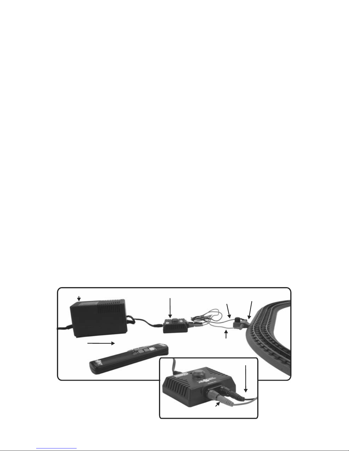
3. Plug the power supply (Z-500, Z-750, or Z-1000) barrel jack into the port
labeled “Power” on the Receiver. Using the RealTrax Wire Harness plug the colorcoded wires from the Receiver to the Lighted Lock-on.
4. Make sure that the engine and cars are properly assembled and coupled on the
track and then plug the power supply (Z-500, Z-750, or Z-1000) into any 110 volt
AC wall outlet. You will know that you have power to the receiver and the track if
you see the green LED atop the Receiver and the green light atop the Lighted
Lock-on will come on. Subsequent pushes of any buttons on the remote will cause
the green LED atop the Receiver to blink, indicating it is receiving the signal.
NOTE: Power must be applied as described above or the DCS Remote
Commander will not control or operate your train.
Red Harness
Wire/Plug
Black Harness
Wire/Plug
Lighted Lock-on
Receiver
MTH Power Supply
Remote
Red Harness
Wire/Plug
Black Harness
Wire/Plug
DCS Remote Commander
3
INSTALLING THE DCS REMOTE COMMANDER
AND CONNECTING POWER
 Loading...