

OPERATOR’S
M
ANUAL
Fifth Edition
www.mthtrains.com
Take Total Control
SYSTEM REQUIREMENTS
Maximum Power Input:
AC Power Supply
0-22VAC, 190VA, 10.0 AMP
DC Power Supply
24VDC, 10.0 AMP
Auxiliary Power Supply
12-22VAC, 1.5 AMP
Welcome to the world of digital command control! M.T.H. Electric Trains® has
developed the most advanced and user-friendly layout control system available in model
railroading today. The Digital Command System (DCS) allows you to achieve realistic
operation heretofore unknown in the hobby. DCS was designed so that even the most
advanced operations can be performed easily, so you can quickly begin to enjoy the
hobby at a whole new level.
With DCS you can control every command-capable locomotive on your layout, including
TMCC locomotives, independently. For Proto-Sound® 2.0 locomotives, you can adjust
lighting, chuff rate or diesel rev level, sound and smoke volume for each locomotive; dial
up a specific scale speed; program multiple-headed locomotives to act as one; record and
playback an operational script; and much, much more.
These operating instructions include Quick-Connect instructions that tell you how to set
up a loop of track quickly and get running right away, so you can gain the benefit of
DCS command features as soon as possible. The Quick-Connect section is followed by
more advanced connection and operation information.
CAUTION: ELECTRICALLY OPERATED PRODUCT:
Recommended for Ages 14 and up. Not recommended for children under 14 years of age without adult supervision. As with
all electric products, precautions should be observed during handling and use to prevent electric shock.
WARNING: When using electrical products, basic safety precautions should be observed, including the following:
Read this manual thoroughly before using this device.
- M.T.H. recommends that all users and persons supervising use examine the hobby transformer and other electronic
equipment periodically for conditions that may result in the risk of fire, electric shock, or injury to persons, such as damage
to the primary cord, plug blades, housing, output jacks or other parts. In the event such conditions exist, the train set
should not be used until properly repaired.
- Do not operate your layout unattended. Obstructed accessories or stalled trains may overheat, resulting in damage to your
layout.
- This train set is intended for indoor use. Do not use if water is present. Serious injury or fatality may result.
- Do not operate the hobby transformer with damaged cord, plug, switches, buttons or case.
This product may be protected by one or more of the following patents: 6,019,289; 6,280,278; 6,281,606; 6,291,263; 6,457,681;
6,491,263; 6,604,641; 6,619,594; 6,624,537; 6,655,640.
©2014, M.T.H. Electric Trains®, Columbia, MD 21046

Table of Contents
Chapter 1: Introduction To DCS................................................................................... 6
The DCS Remote Control................................................................................... 7
The Track Interface Unit (TIU).......................................................................... 8
The Accessory Interface Unit (AIU)................................................................. 9
Recommended Wiring Methods......................................................................... 10
Chapter 2: Quick Start In Command Mode.............................................................. 14
Overview................................................................................................................. 15
Using The Remote Control................................................................................. 16
Accessing A Locomotive..................................................................... 17
Selecting And Starting A Locomotive............................................... 19
Making The Engine Go....................................................................... 20
Reversing Direction.............................................................................. 21
Activating Basic Sounds....................................................................... 21
Shutting Down A Locomotive........................................................... 22
“Jumping” Between Active Egnines.................................................. 22
Controlling All Active DCS Engines At Once................................ 23
Chapter 3: One-Touch Locomotive Control.............................................................. 24
Labor/Drift............................................................................................................ 25
Boost/Brake........................................................................................................... 26
Coupler Operation................................................................................................ 27
Smoke On/Off Control...................................................................................... 27
Volume Increase Control...................................................................................... 27
Engine Start Up..................................................................................................... 28
Engine Sound On/Off Control......................................................................... 28
Volume Decrease Control.................................................................................... 28
Engine Shut Down............................................................................................... 29
Headlight On/Off Control................................................................................. 29
Proto-Cast On/Off Control............................................................................... 29
Passenger/Freight Announcements................................................................... 30
Read Button........................................................................................................... 31
Doppler On/Off Control................................................................................... 31
Emergency Stop.................................................................................................... 31
SoftKey Operation................................................................................................ 32
Using The Remote Control Backlight............................................................... 35
Using The Remote Control Microphone.......................................................... 35

Chapter 4: Menu Operations - Sound......................................................................... 36
Introduction.......................................... ................................................................ 37
Bell, Horn, Engine/Accent Volume.................................................................. 38
Proto-Whistle........................................................................................................ 39
Chuff Rate............................................................................................................. 40
Proto-Chuff............................................................................................................ 41
Cab Chatter............................................................................................................ 41
Brakes...................................................................................................................... 42
Clickty Clack.......................................................................................................... 42
Custom Sounds...................................................................................................... 43
Auto Coupler......................................................................................................... 47
Doppler Loop........................................................................................................ 48
External Mic........................................................................................................... 49
Chapter 5: Menu Operations - Control....................................................................... 50
Smoke Output Control........................................................................................ 51
Ditch Light Control.............................................................................................. 52
Setting Maximum Engine Speed........................................................................ 52
Setting Acceleration Rate..................................................................................... 53
Setting Deceleration Rate..................................................................................... 53
Setting Direction Control.................................................................................... 54
Activating Labored Smoke.................................................................................. 54
Brake Boost............................................................................................................ 55
Chapter 6: Menu Operations - System........................................................................ 56
Engine Setup.......................................................................................................... 57
Adding Engines..................................................................................... 57
Editing Engines..................................................................................... 60
Deleting Engines................................................................................... 61
Track Setup............................................................................................................. 62
Adding Tracks....................................................................................... 62
Editing Tracks....................................................................................... 65
Deleting Tracks..................................................................................... 66
Switch Setup........................................................................................................... 67
Adding Switches.................................................................................... 67
Editing Switches.................................................................................... 68
Deleting Switches................................................................................. 69
Accessory Setup..................................................................................................... 70
Adding Accessories.............................................................................. 70
Editing Accessories.............................................................................. 70
Deleting Accessories............................................................................ 71
TIU Setup............................................................................................................... 72
Add/Edit/Delete TIU......................................................................... 72
Super TIU............................................................................................... 73
Reset TIU............................................................................................... 74
Adjusting The Remote LCD Contrast.............................................................. 74
DCS Setup.............................................................................................................. 74
Track Signal............................................................................................................ 75
Remote Setup......................................................................................................... 76
Setting The Remote Control Address............................................... 76
Remote Powerdown............................................................................. 77
Remote Back Up................................................................................... 77
Quickset Speed...................................................................................... 78
Operating Mode.................................................................................... 79

Chapter 7: Menu Operations - Advanced.................................................................. 80
Creating A Lashup................................................................................................ 81
Setting Up A Route.............................................................................................. 89
Setting Up A Scene.............................................................................................. 91
Recording/Playing Back An Operating Session.............................................. 94
Resetting Engine Features................................................................................... 96
Reading Engine Information.............................................................................. 97
Configuring DCS For 50 or 60Hz AC Input................................................... 97
Chapter 8: Universal Locomotive & Accessory Operation.................................. 98
Advanced Wiring.................................................................................................. 99
Wiring Thru A Variable Channel Only............................................. 99
Connecting TMCC To A DCS Layout............................................. 100
Wiring For Use With A Z4000 Remote Receiver........................... 101
Large Layouts........................................................................................ 102
One Gauge Layouts............................................................................. 103
Track Signal Improvements................................................................ 104
Setting Up A Programming Track.................................................... 106
All Mode Tracks................................................................................... 107
Universal Locomotive Control........................................................................... 109
Operating TMCC Engines.................................................................. 110
Editing A TMCC Engine Address.................................................... 112
Operating Conventional Engines...................................................... 113
®
Operating Proto-Sound
2.0 Engines In Conventional Mode... 114
Operating With Multiple Users.......................................................... 115
Switch And Accessory Operation...................................................................... 117
Smoking Whistle................................................................................................... 118
Appendix A: SoftKey Codes/Screen Messages....................................................... 120
Appendix B: Frequently Asked Questions................................................................ 124
Appendix C: Trouble-Shooting..................................................................................... 128
Appendix D: Transformer Compatibility Chart...................................................... 140
Appendix E: Station Stop Proto-Effects Operation............................................... 142
Appendix F: Glossary...................................................................................................... 144
Appendix G: Index........................................................................................................... 146
Service & Warranty............................................................................................................ 147

1
Chapter 1
DCS Remote......................................... 7
Track Interface Unit (TIU)................. 8
Accessory Interface Unit (AIU)......... 9
Recommended Wiring......................... 10
Introduction To DCS
DCS Command System User’s Guide
6
DCS Command System User’s Guide
Introduction To DCS
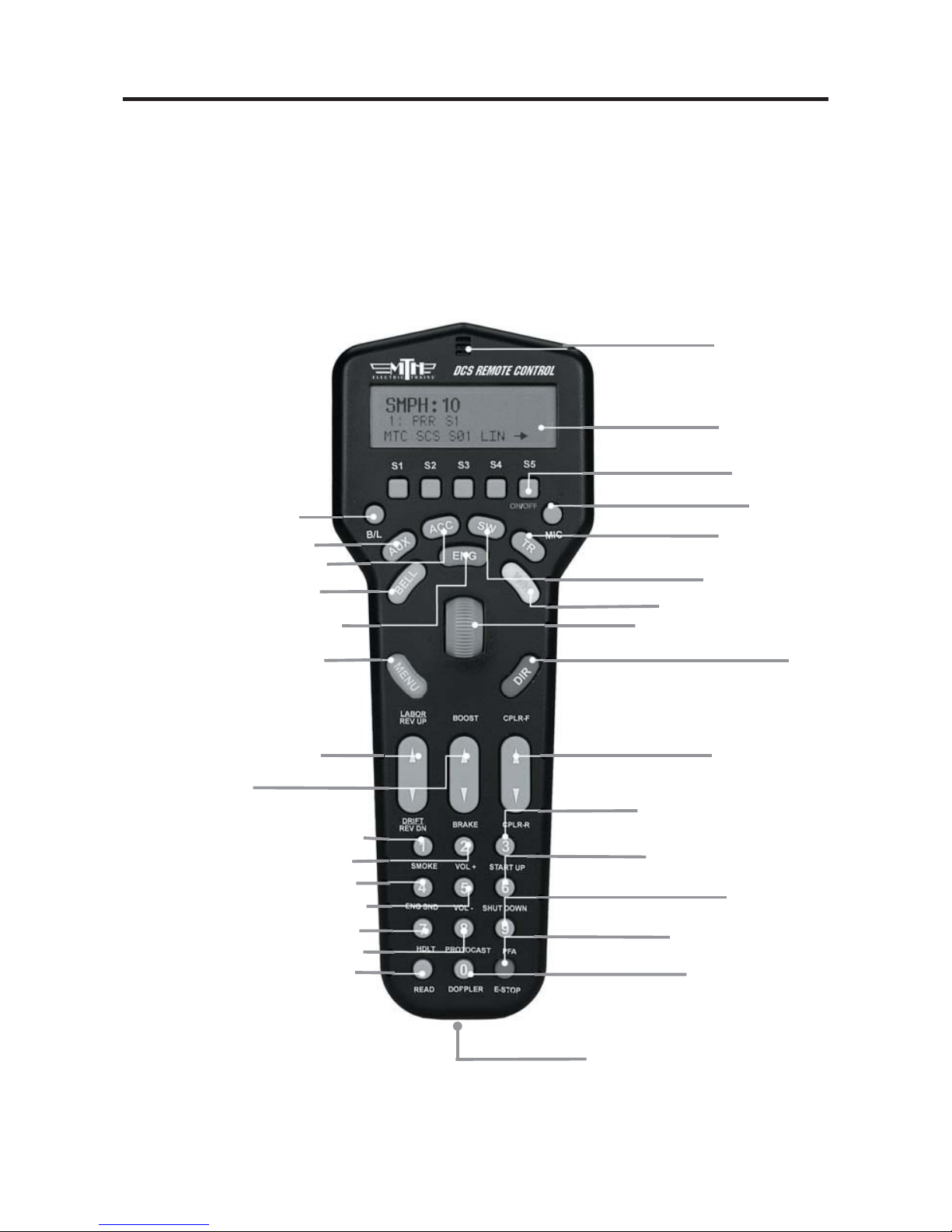
DCS Remote Control
This is the device you will use the most when controlling your trains. It communicates
with the TIU via a 900MHz signal in much the same manner as your cordless phone
communicates with its base. The remote does not talk directly to the locomotive or
accessory you are controlling.
7
B/L - Screen backlight on/off
AUX - Auxiliary menu
ACC - Accessory menu
BELL - Rings bell
ENG - Engine menu
(to select and control engines)
MENU - Access 4 main menus
Sound, Control, System, Advanced
LABOR/REV UP OR DRIFT/REV DN
Makes an engine sound like
it's working harder or easier
BOOST/BRAKE
Temporarily Raises or Lowers Speed
SMOKE - Turns smoke unit on & off
VOL+ - Globally increases all sounds
VOL- - Globally decreases all sounds
ENG SND - Silences engine sounds
HDLT - Turns headlights on & off
PROTOCAST - Activates Proto-Cast™
READ - Search for TIUs, AIUs and
Proto-Sound
®
2.0 Engines on the track
DOPPLER - Activates
Proto-Doppler™
E-STOP - Cuts power to
all tracks
PFA - Activates
Passenger/Freight Sounds
SHUT DOWN - Deactivates
all sound, smoke & lights
START UP - Activates sound,
smoke & lights
Programming Port - Tether
attaches between remote and TIU for
programming new software features
CPLR-F/CPLR-R
Fires front & rear couplers
THUMBWHEEL - Throttle &
selection (scroll & press) tool
DIR -
Changes locomotive direction
W/H - Blows whistle/horn
SW - Switch menu
TR - Track menu
(Access various tracks / blocks on your layout)
MIC - Turns
Proto-Dispatch™ on & off
MICROPHONE
LCD DISPLAY
SOFTKEYS -
Activate locomotive features

DCS Command System User’s Guide
Introduction To DCS
The Track Interface Unit
Also known as the TIU, the Track Interface Unit is the brains behind the DCS system.
Connected between the transformer and the track, the TIU receives signals from the
DCS remote control and relays those signals to each train you are controlling via the rails.
The type of signal relayed to the train depends on the operating mode at the time. If
operating conventionally, the TIU will raise and lower track voltage to control engine
speed. If operating in command mode, the TIU will send a digital signal to each train
you are controlling via the track rails.
This digital signal is very powerful and contains a lot of information much like the digital
signals used in today’s high tech products. These digital signals are what allow DCS to
perform the hundreds of functions designed into the system.
8
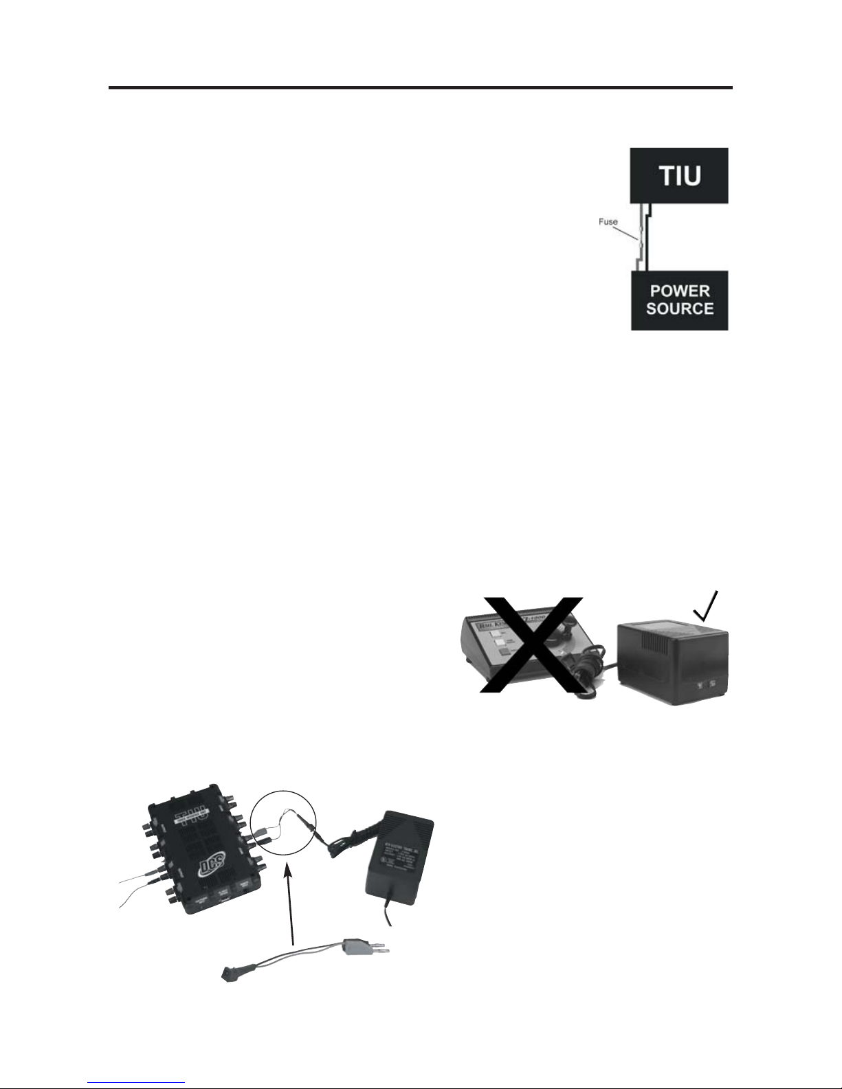
ATTENTION
TIU contains internal
fuses. If there is no
output, open the case (6 Screws)
and check the fuse.
More information on Page 133.

DCS Command System User’s Guide
Introduction To DCS
The Accessory Interface Unit
The Accessory Interface Unit, also known as the AIU, plugs into the TIU and controls
any accessory or switch wired to it. Each AIU can control up to 10 switches and 10
accessories and features the ability to turn the accessory on or off, or activate it momentarily.
The AIU essentially acts as a large relay and simply replaces the manual switches that are
normally used to turn on and off model railroading accessories. Connection to the TIU
is done through a special cable (included with the AIU) and up to five AIUs can be daisychained to one TIU.
9
ACC
IN = Armature of Relay
1 = NO (normally open)
2 = NC (normally closed)
SW
IN = AC Common
1 = Straight
2 = Curved
ATTENTION:
Connecting the TIU to the AIU output may cause damage to earlier
model AIU’s.

Introduction To DCS
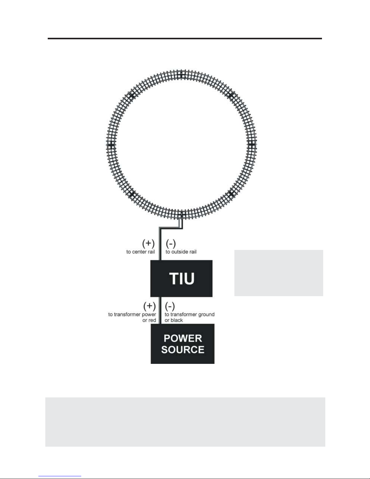
Recommended Wiring Method
It is important for good operation to make the most efficient use of the power and digital signal available on your track. Poor wiring and bad connections offer resistance and
can interfere with receipt of the DCS signal and limit the number of engines and cars
you can run on your track. Be sure to use proper wire (we recommend 16-gauge or larger paired wire, like speaker wire) and good connections (good connections mean crimp or
solder).
Because center rail blackening is not conductive, you may find that the blackening on
your track creates resistance that drains power and signal. If so, use Scotch-Brite®, finegrit sandpaper, or an LGB® track cleaning block to clean the blackening off the top of
your center rail.
Advanced wiring information and diagrams, including wiring for layouts using blocks for
conventional operation, are located in the “Universal Locomotive and Accessory
Operation” section of this manual.
Optimal Performance Wiring Principles:
-
Use 16-gauge or larger paired wire (such as speaker wire)
-
Use a star pattern (home run wiring) to wire directly from the TIU to each
lock-on
-
Use a terminal block to carry power and signal from one TIU channel to
multiple lock-ons
-
Avoid common bus wiring
-
Solder for tight connections (not required)
-
Clean the blackening off the top of the center rail (if necessary)
-
Power accessories and turnouts via auxiliary, not track, power
-
Place a lock-on (or wire directly to track) approximately every 25 linear feet,
both center and one outside rail
10
DCS Command System User’s Guide
DCS Command System User’s Guide
Introduction To DCS
Recommended Wiring Method
11
Note: This very quick wiring scheme (through the Fixed In 1 and Fixed Out 1 inputs) allows for
operation of the connected loop of track in DCS command mode only. Please see the “Advanced
Connection” section of this manual in the “Universal Operation” chapter for all the wiring options if
you have more complex wiring and operational needs, including conventional mode and TMCC operation.
Maximum Power Input
0-22VAC,190VAC, 10AMP
OR
0-24VDC, 10AMP

Introduction To DCS
Transformer Note: Although we do not recommend using the DCS System with homemade
transformers or those that put out more than 12 amps, virtually any commercial AC hobby power supply
will work with DCS. (See Transformer Compatibility Chart, p. 114) Bear in mind that as you begin
to run more and longer trains together, you need to have lots of power on the track. For this reason, we
recommend that railroaders with large layouts and long trains use M.T.H.’s Z-4000®(Item No. 40-
4000), which is the most powerful UL-rated transformer on the market.
Optional Additional Equipment Shown:
M.T.H. Terminal Block (Item No. 50-1014)
The screws in each terminal strip of this terminal block are electrically connected to
one another, making it easy to wire the TIU’s output into the binding posts and then
wire out to several lock-ons from different terminal pairs.
Recommended Wiring Method
12
DCS Command System User’s Guide
Introduction To DCS
Controller
Brick
TIU
Brick
TIU/Barrel Jack Adapter Cable
(50-1017)
Recommended Wiring Method - Older Transformers
Older transformers, like the Lionel postwar ZW or KW models
employ a bi-metallic strip to act as a circuit breaker. The strip
responds to heat as high current flows through the transformer. If
enough heat is generated by the high current, the strip will open the
circuit and prevent further current from flowing out of the transformer. The bi-metallic strip is not a precise overload protection
device and does not measure the current. As a result, it may not trip
when excessive amps are being generated by the short circuit. Should
the strip thus fail to trip, excessive and potentially harmful current
could be sent through the TIU.
MTH therefore recommends that any user employing an older transformer that does not
meet today’s U.L. standards install inline fuses or circuit breakers between the transformer
and the TIU input channels. An AG3C “fast-acting” or “fast-blow” fuse rated at 15 amps
would be suitable protection. These can be obtained from most hardware or electronic
stores including Radio Shack. Users will also need an inline fuse holder to house the fuse.
Radio Shack sells a heavy duty model, part number 27-1217.
Recommended Wiring Method - Electronic Transformers
Any transformer employing two parts, a brick
(step down transformer) and a controller (used
to vary the voltage output) may cause operational problems due to low power or poor DCS
signal. To correct this problem, MTH recommends connecting only the brick to the TIU
inputs. In addition, check the output voltage of
the transformer; it should not exceed 22 volts
(or 18 volts if lighted cars are used on the track).
When using the Z-500, Z750 or
Z1000 electronic type transformer use
an adapter cable, MTH item 50-1017,
to connect the brick directly to the
TIU input as shown below. DO NOT
use the controller portion of an electronic type transformer.
DCS Command System User’s Guide
13

2
Chapter 2
Overview................................................ 15
Using The Remote............................... 16
Accessing The Engine......................... 17
Selecting & Starting The Engine....... 19
Making The Engine Go...................... 20
Reversing Direction............................. 21
Basic Sounds......................................... 21
Shutting Down The Engine............... 22
"Jumping” Between Active Engines.. 22
Controlling ALL Engines At Once... 23
Quick Start In Command Mode
DCS Command System User’s Guide
14

DCS Command System User’s Guide
Quick Start: Command Mode
Setting Up And Using DCS - An Overview
Setting up the DCS system for simple command mode operation is quick and easy. The
eight steps below are all that is required to begin operating a single Proto-Sound 2.0
equipped engines in command mode on a simple layout. Each step is explained in more
detail on pages 16 - 23.
1. Connect the TIU Voltage In Channel to the Transformer Terminals.
Connect the black negative (-) and red positive (+) wires from your transformer to the
TIU’s black and red banana jacks (respectively) on the “Fixed Voltage In1” channel.
Make sure the connections are tight.
2. Connect the TIU Out Channels To The Track. Connect wires from
the red and black “Fixed (DCS) Out1” banana jacks to your track or lock-on. If you
connect directly to the track, red (hot) must be connected to the center rail and black
(ground) to the outer rail.
3. Put four AAA batteries in the handheld.
4. Put a Proto-Sound 2.0 equipped engine on your track.
5. Turn on your transformer and increase the throttle to 18 Volts (or
between ¾ and full power for older transformers).
6. Add the engine into the remote’s memory
- see Using The Remote and
Accessing The Locomotive beginning on page 16.
7. Select and Start Up the engine - see Selecting and Starting The Locomotive on
page 18.
8. Make the engine go by rolling up the throttle - see Making The Engine
Go, Reversing Direction and Basic Sounds beginning on page 20.
15
Quick Start: Command Mode
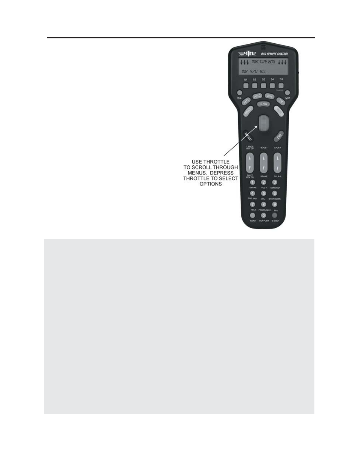
Using the Remote
When using the thumbwheel to scroll up
and down, whether to change a locomotive’s speed or to scroll through features,
you should roll gently over the thumbwheel; do not press too hard. The
thumbwheel is pressed down to select
and activate features, as discussed in the
“Advanced Locomotive Operation”
section.” Do not attempt to scroll and
press at the same time.
When accessing Menu functions, you will
use a combination of button presses and
thumbwheel scrolls to access and move
through menus, as described in the
“Advanced Operation” chapter.
The two Fixed and two Variable channels of the TIU are built differently and serve different functions, although the same DCS signal is sent to the track on all four channels.
Variable channels have internal circuitry that allows them to vary track voltage from
within the channel. That means you can vary the voltage on tracks connected to a
Variable channel from the DCS handheld. These channels are perfect for tracks on
which you want to run conventional mode engines (e.g., original Proto-Sound, PostWar,
etc.) via the DCS handheld.
Fixed channels are straight throughputs. That is, the voltage that enters these channels is
the same voltage that comes out, with no voltage variation within the TIU. These channels are ideally meant for command mode operation only. There is, however, one way to
set up Fixed tracks so that you can operate conventionally via the DCS handheld. If you
are using a Z-4000® to power tracks connected to the Fixed channels, you may set up a
Z-4000 remote receiver (Item No. 40-4002) for those throttles. The DCS handheld is
designed to communicate with the Z-4000 remote receiver, and it can vary track voltage
that way. Please see the “Advanced Wiring” section of this manual in the “Universal
Locomotive and Accessory Operation” chapter for more information about this option.
16
DCS Command System User’s Guide
DCS Command System User’s Guide
Quick Start: Command Mode
Accessing the Locomotive
When a Proto-Sound 2.0 engine is placed on a track connected to a TIU, the DCS system will bring it up in command mode by default. Because DCS command operation differs in some fundamental ways from conventional
operation, please read this section in full before running
your trains in command mode.
With a single M.T.H. Proto-Sound 2.0 engine (and tender
if the engine has one) on the track and voltage applied to
the track, press the Menu Button and complete the steps
diagrammed below.
17
NOTE: When you first power
up the track, your Proto-Sound
2.0 locomotive remains silent
and dark. This is normal; it is
in Command Mode and will
not start up until you tell it to.
The instructions below will tell
you how to access and operate
that locomotive.
Note: Pressing the S2 Softkey
under S/U provides a shortcut to the
Engine Setup Menu
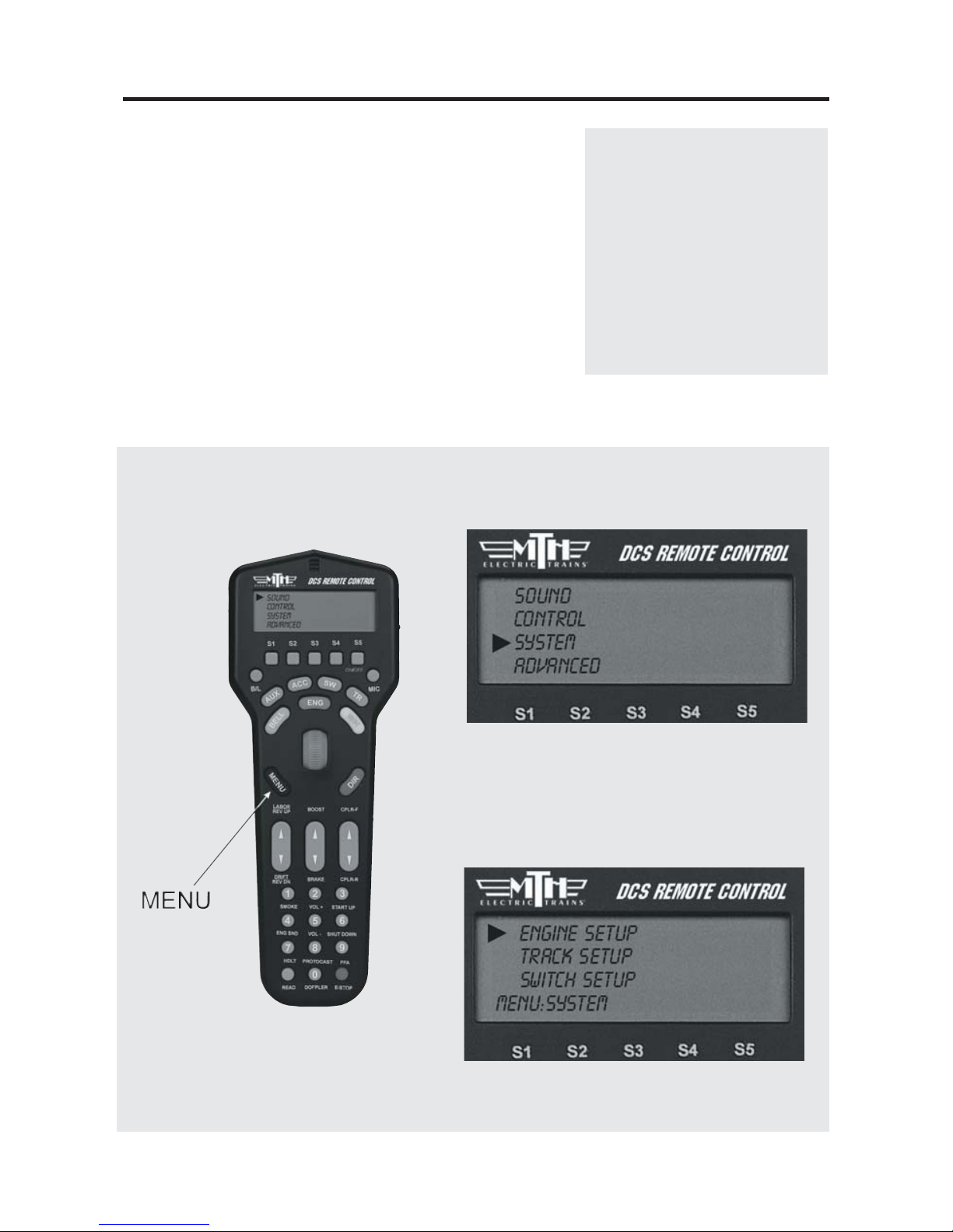
1. Press the Gray MENU
button to bring up the four
main menus in the DCS system.
2. Using the thumbwheel, scroll down the
menu list until you arrive at System.
3. Press the thumbwheel to enter the
System Menu. Your screen should reveal
at the bottom that you are in the System
Menu.

DCS Command System User’s Guide
Quick Start: Command Mode
Wait until the LCD says the engine was
added and returns to the engine menu
addressing that engine. Because M.T.H.
features the SmartRead system, your
engine tells the TIU its name and you do
not need to enter any information in
order to add the engine. The LCD will
show you the engine you have added.
If you want to add additional engines,
remove the added engine from the track,
place the new engine on the track, and
repeat steps 1 and 2. You need to
complete these steps only once per
engine, when you first add it to your
system, not each time you place a
previously added engine on the track.
Adding Many Engines
If you own several Proto-Sound 2.0
engines and anticipate buying many others, you may find it convenient to establish a dedicated programming track
rather than removing all other engines
from your track every time you add a
new one. Please see the “Advanced
Wiring” section of this manual in the
“Universal Locomotive and Accessory
Operation” chapter for instructions.
See the System Menu/Engine Setup section in the “Menu Operation” chapter(s)
of this book for instructions on renaming, renumbering, or deleting your
engines.
18
4. Scroll and select Engine Setup from the
available choices in the System Menu.
5. Scroll and select Add Engine from the
available choices in the Engine Setup Menu.
6. Scroll and select Add MTH Engine
from the available choices in the Engine
Setup Menu.
Quick Start: Command Mode
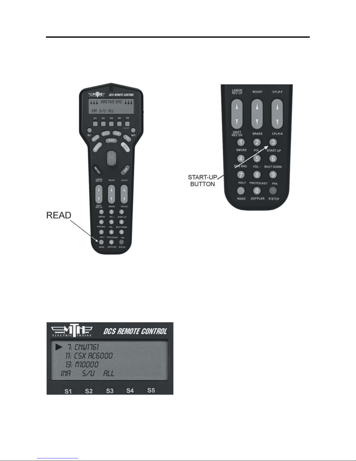
1. When all Proto-Sound 2.0 engines are
added, put the ones you want to run on
the track and press READ to put them
on the active engine list.
3. Press START UP (3 on the keypad)
to activate the lights and smoke and
initiate the engine start-ip sounds.
2. Press the green ENG button and
scroll the thumbwheel until the arrow
points to the engine that you want to
address. Press the thumbwheel to select
the engine.
DCS Command System User’s Guide
4. Your locomotive is now ready to run.
You need to press the START UP button every time you want to run an engine
in a new session.
19
DCS Command System User’s Guide
Quick Start: Command Mode
Active and Inactive Engines
Once an engine is added to your system, it will remain in place and always appear on the
LCD engine list until you delete the engine. To make it easier to manage the engines
being used in a given session, there are Active and Inactive engine lists. Engines currently
in use are on the Active list, while other engines wait on the Inactive list until they are
activated.
You may update the Active and Inactive lists any time you change the locomotives on the
track simply by pushing the READ button, or you may change the status of each engine
individually.
To activate an engine on the inactive list, scroll so that the arrow is pointing to it in the
engine list and press the thumbwheel to move the engine to the active list. Proto-Sound
2.0 engines must be on a powered track to be activated.
To inactivate an engine on the active list, scroll so the arrow is pointing to it in the engine
list and press the S1 key (under INA) to move the engine to the inactive list.
DCS Tip: Operators who remove engines from the track when not in use will find
READ the easier method, while those who park their engines in a roundhouse – still on
the track – will prefer to change engine status individually.
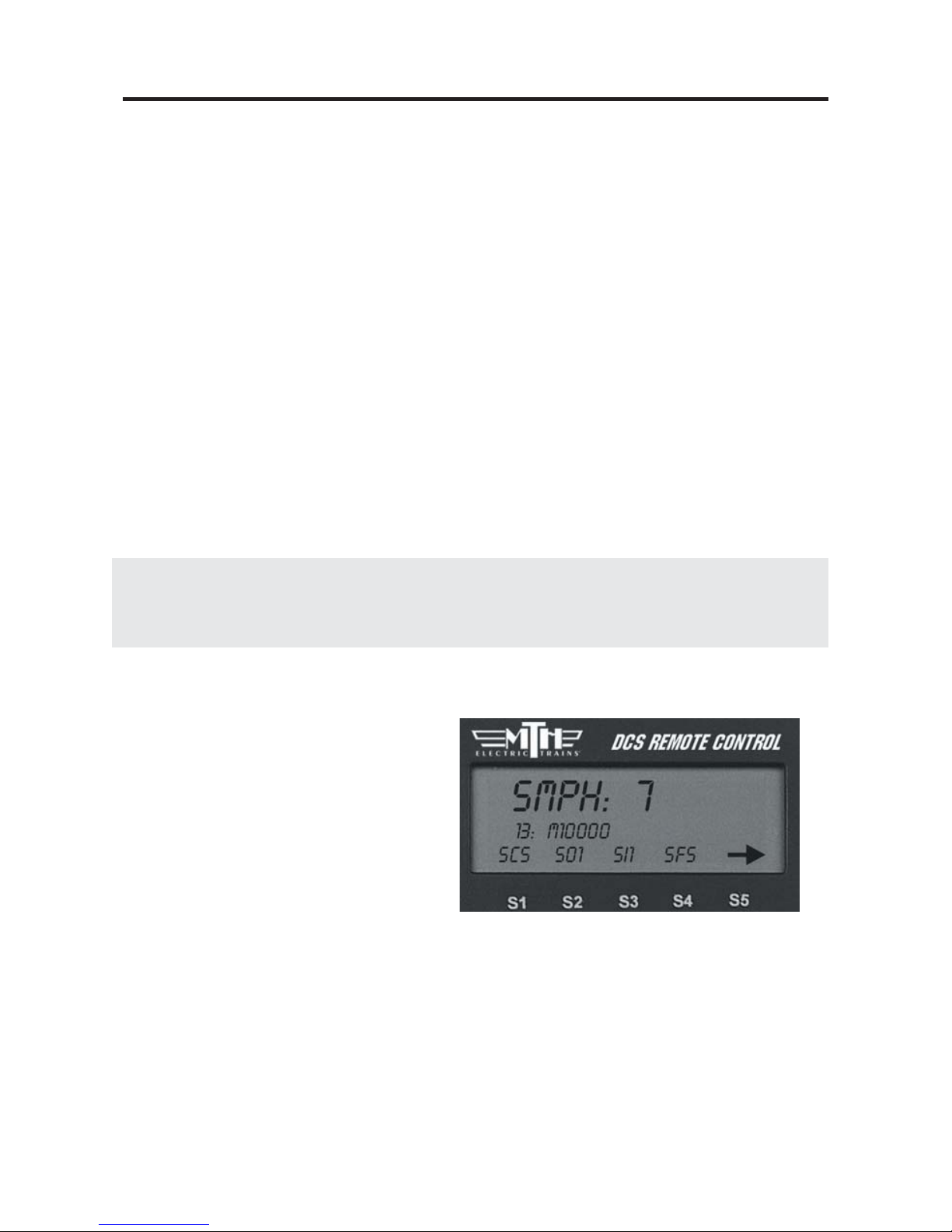
Making the Engine Go
There is no neutral in DCS command
mode; the default start-up direction is
forward. You simply roll the thumbwheel up to make the locomotive go
forward. The LCD display on the DCS
remote will display the engine’s speed in
SMPH (scale miles per hour). Roll the
thumbwheel down to slow or stop the
engine.
20

DCS Command System User’s Guide
Quick Start: Command Mode
Reversing Direction
Because there is no neutral in DCS command mode,
DCS engines go directly from forward to reverse.
There are two ways to change directions in command
mode:
Press the red DIR (Direction) button while you are in motion to drop the locomotive’s
speed to 0 smph and change its direction. Wait for the engine to come to a complete
stop, then roll the thumbwheel to the desired speed in the new direction.
OR
Scroll back to 0 SMPH, wait for the engine to come to a complete stop, press DIR, and
then roll the thumbwheel to the desired speed and the new direction. Pressing Direction
once takes you directly from forward to reverse and vice-versa.
If you roll the thumbwheel to 0 SMPH then
resume motion without pressing Direction, the
engine will remain in its current direction. If you
mistakenly press “Direction” to stop the engine but
want to continue in the same direction, press
“Direction” one more time.
Basic Sounds
The yellow BELL and white W/H buttons operate the bell and horn the same way in
command mode that they do in conventional mode:
Horn/Whistle - The horn/whistle will sound for as long as you depress the button. It
will stop when you release the button. The Proto-Sound 2.0 horn/whistle’s ending
sounds are designed to vary with the amount of time you hold the button.
Bell - To sound the bell, firmly press and release the Bell button. To turn the bell off,
press and release the Bell button again. The bell will continue to ring from the time you
turn it on until you press and release the button again to turn it off. When you turn it off,
the bell sound effect fades out, ringing fainter until it stops, just like a real bell.
21
Note: If you roll up the
thumbwheel before the engine comes
to a complete stop, the engine will
continue in the same direction.
DCS Command System User’s Guide
Quick Start: Command Mode
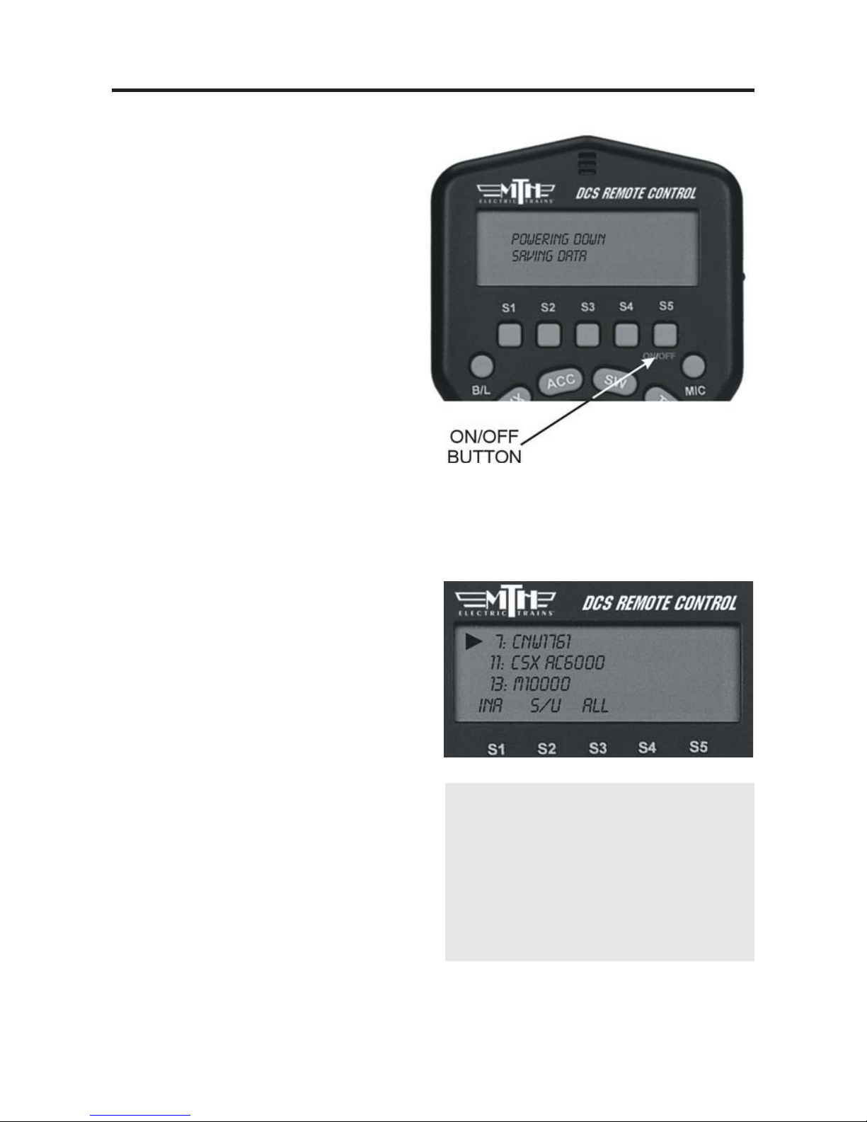
Shut Down
1. To shut down the locomotive at the
end of a session, stop the engine.
2. Press the Shut Down key (6) to turn
off the sound, smoke, and lights. The
locomotive will play a short series of realistic shutdown sounds before it falls
silent. Repeat with all active engines.
Note that power is still on the track after
shut down.
3. Press and hold ON/OFF button (S5)
until the LCD shows that the handheld is
saving data. It will soon turn off. If you
forget to turn off the remote, it will
power down automatically after 10 minutes of non-use. Turn off your transformer.
Moving Between Active Engines
When more than one engine is addressed
and operating, you can easily move among
the different engines and control each in
turn.
1. Press the green ENG button.
2. Scroll the thumbwheel until the arrow
points to the engine you want to address,
and press the thumbwheel to select it.
22
DCS Tip: When you press ENG, the
arrow will point at the last engine
addressed, allowing you to jump easily
back-and-forth between two engines.
This Jump function works like the
“Last” or “Previous Channel” button
on a TV remote control.

Quick Start: Command Mode
Controlling All Active DCS Engines at Once
If only DCS engines are on the track, you can send the same command to them all at the
same time. To issue the same command to all active Proto-Sound 2.0 engines simultaneously:
1. Press READ to ensure a correct active
engine list.
2. Press the green ENG button.
3. Press the S3 softkey under the ALL
choice (beneath the scroll list of engines)
4. Send the commands as described in the
One-Touch Operation Chapter.
DCS Tip: if an engine is listed as active on the LCD but is not on the track or is listed
as inactive but is on the track, the ALL command will not work. Press READ to update
the active engine list. Active TMCC engines will not respond in ALL mode.
Congratulations! You are now operating your locomotive in
command mode! For more instructions on basic command mode
operation, see the “One-Touch Operation” chapter of this manual.
DCS Command System User’s Guide
23

3
Chapter 3
Labor/Drift........................................... 25
Boost/Brake.......................................... 26
Coupler Front/Rear............................. 27
Smoke On/Off..................................... 27
Volume Increase................................... 27
Start Up.................................................. 28
Engine Sound On/Off........................ 28
Volume Decrease.................................. 28
Shut Down............................................. 29
Headlight On/Off............................... 29
ProtoCast On/Off............................... 29
Passenger/Freight Announcements.. 30
Read........................................................ 31
Doppler On/Off.................................. 31
Emergency Stop.................................... 31
Softkeys.................................................. 32
Backlight................................................ 35
Microphone........................................... 35
One Touch Locomotive Operation
DCS Command System User’s Guide
24
DCS Command System User’s Guide
One-Touch Locomotive Operation
The most frequently accessed features can be controlled via the One-Touch buttons on
the DCS remote handheld. These buttons will affect only the locomotive selected and
shown in the LCD. You can watch the LCD screen to see which engine you are addressing and what features you are turning off and on.
Many of the most commonly used One-Touch buttons are located on the lower half of
the remote:
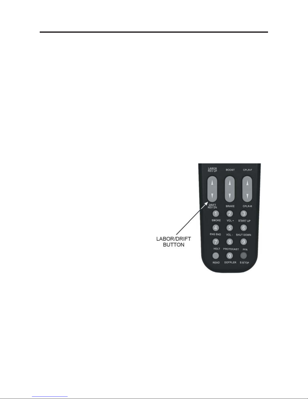
LABOR REV UP / DRIFT REV DN:
Press the top end of the rocker switch to change engine sounds to labored chuff or higher engine revolution levels without changing speed. You will see an increase of smoke
output corresponding to the sounds of the engine working harder, and the LCD will
show Labored Chuff/Rev Up.
OR
Press the bottom end of the rocker switch
to change engine sounds to drift or lower
revolution levels without changing speed.
You will see a decrease of smoke output
corresponding to the sounds of the engine
working less hard and the LCD will show
Drift Chuff/Rev Down.
For diesel or electric engines, the change in
sound will become more pronounced with
each press of the switch until you reach the
system limit of eight REV levels. The
sound level will remain as you set it until
you press the opposite end of the rocker
switch to return the engine sounds step-bystep to normal. The system automatically
resets the sound REV level to a protoypical level based on the engine’s speed.
For steam engines, as soon as you release the button, the sound will return to the normal
steam chuff setting.
25
DCS Command System User’s Guide
One-Touch Locomotive Operation
There are three degrees of chuff (drift, normal, labor) in steam engines and eight degrees
of diesel revolutions above idle. Your diesel’s default rev sounds depend upon how fast
it is running.
Smoke output in diesel engines increases or decreases relative to engine REV levels.
Note: Your engine’s default setting is to go into labor/drift mode automatically when the
system senses that speed has changed. As soon as you use this rocker switch, the system
is changed from Auto to Manual setting. To put the Labor/Drift setting back into Auto,
you must do it through the menu. See the System Menu/Proto Chuff section of the
“Menu Operations” chapter(s) of this manual for instructions
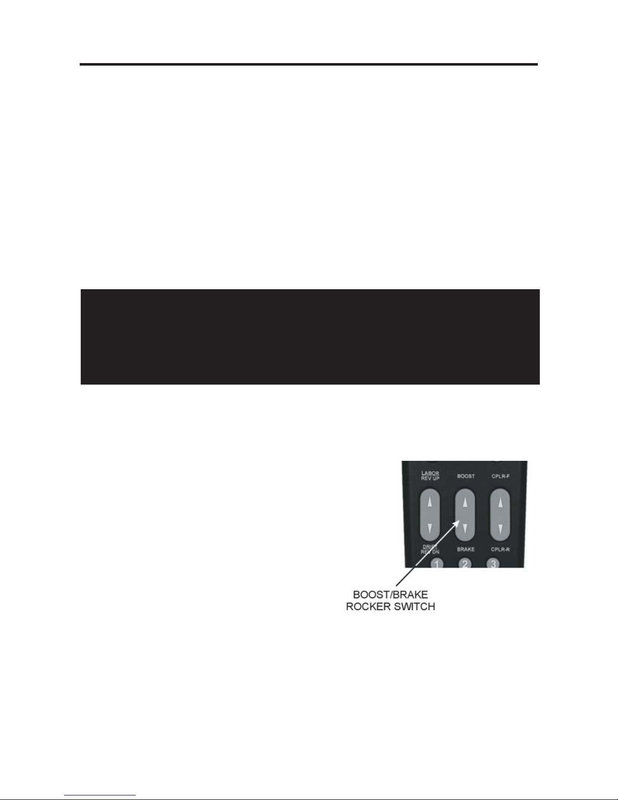
Boost/Brake:
Press and hold top end of rocker switch to
temporarily increase speed of the selected engine.
OR
Press and hold bottom end of rocker switch to
temporarily decrease speed of the selected engine
The speed will continue to change (keep getting
faster or slower) for as long as the button is
pressed, before resuming the set speed when
you release the button.
Please see Page 55 for more on Boost/Brake Operation.
26
CAUTION
Operating your engine in Labor or Rev Up mode with increased smoke output for
extended periods of time uses large quantities of smoke fluid and may cause the
wick to burn if it is not replenished. Check your smoke fluid levels more frequently
than normal if you frequently operate in labor/rev up mode.
DCS Command System User’s Guide
One-Touch Locomotive Operation
CPLR-F / CPLR-R:
Press top end of rocker switch to fire the front
coupler (if your locomotive is equipped with one)
OR
Press bottom end of rocker switch to fire the rear
coupler
When engine sounds are on, coupler release sounds
will play as the coupler is fired.
SMOKE (1):
Press this button to turn the smoke unit on or off
(LCD will show “Smoke = On” or “Smoke = Off ”).
Because of the way the smoke unit works, it may
take a few seconds after pushing the button before
you see the smoke start or stop.
For instructions on setting the smoke density level (to minimum, medium, or maximum), please see the Control Menu in
the “Menu Operation” chapter of this book.
VOL + (2):
Press this button to increase all sound set volumes
above the default settings, up to the maximum level
allowed for the selected engine (LCD will show
“Master Volume Up”). The volume will increase one
level with each button push (until you reach the maximum level) and will remain at the level you set until
you press Vol- (5) to lower volume.
To control the volume of individual elements of the sound set
(i.e. horn/whistle volume, bell volume, engine sounds volume,
and accent sounds volume), see the “Sound” menu in the
“Menu Operation” chapter of this book.
27
One-Touch Locomotive Operation
28
START UP (3):
On start-up, with the engine stopped (at 0
smph), press the button to activate sound,
smoke, and lights (LCD will show “Start
Up”). A newly accessed engine that has
not been started up will move, but it will
run silently without lights or smoke.
ENG SND (4):
Press this button to silence engine and
accent sounds. The horn and bell will still
sound if triggered. Press it again to
restore sounds at the previous volume
(LCD will show “Engine Snd = On” or
“Engine Snd = Off ”).
VOL – (5):
Press this button to decrease all sound set
volumes below the default settings, until
the engine falls silent (LCD will show
“Master Volume Down”). The volume
will decrease one level with each button
push (until you reach the minimum level)
and will remain at the level you set until
you press Vol+ (2) to raise the volume.
To control the volume of individual elements of
the sound set (i.e. horn/whistle volume, bell volume, engine sounds volume, and accent sounds
volume), see the “Sound” menu in the “Menu
Operation” chapter of this book.
DCS Command System User’s Guide
One-Touch Locomotive Operation
29
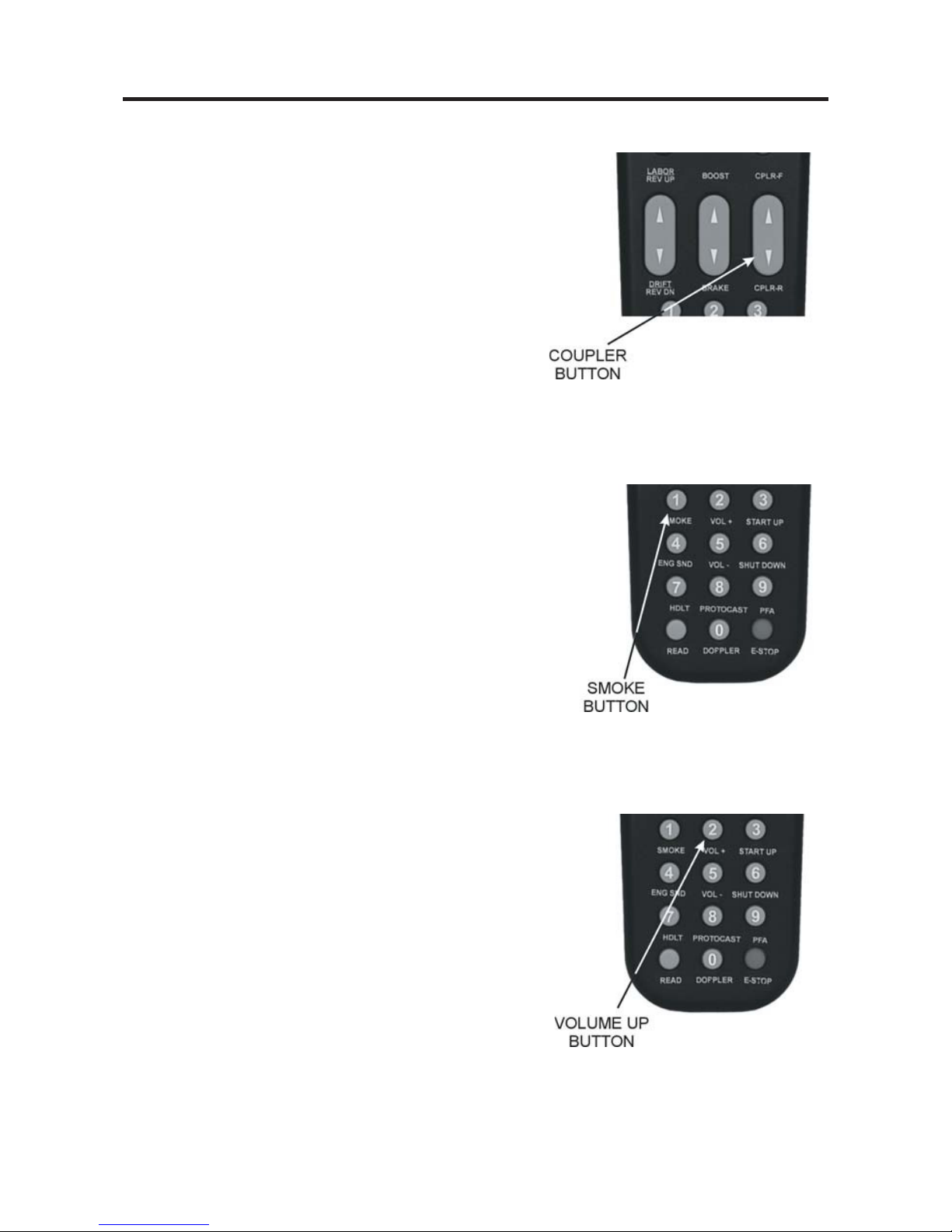
SHUT DOWN (6):
Press this button to turn off sound, smoke,
and lights in preparation for powering down
(LCD will show “Shut Down”). Shut Down
sounds will play, and the engine will fall
silent with the lights off, though it will still
move until you scroll to 0 smph. Note that
power is still on the track after shut down.
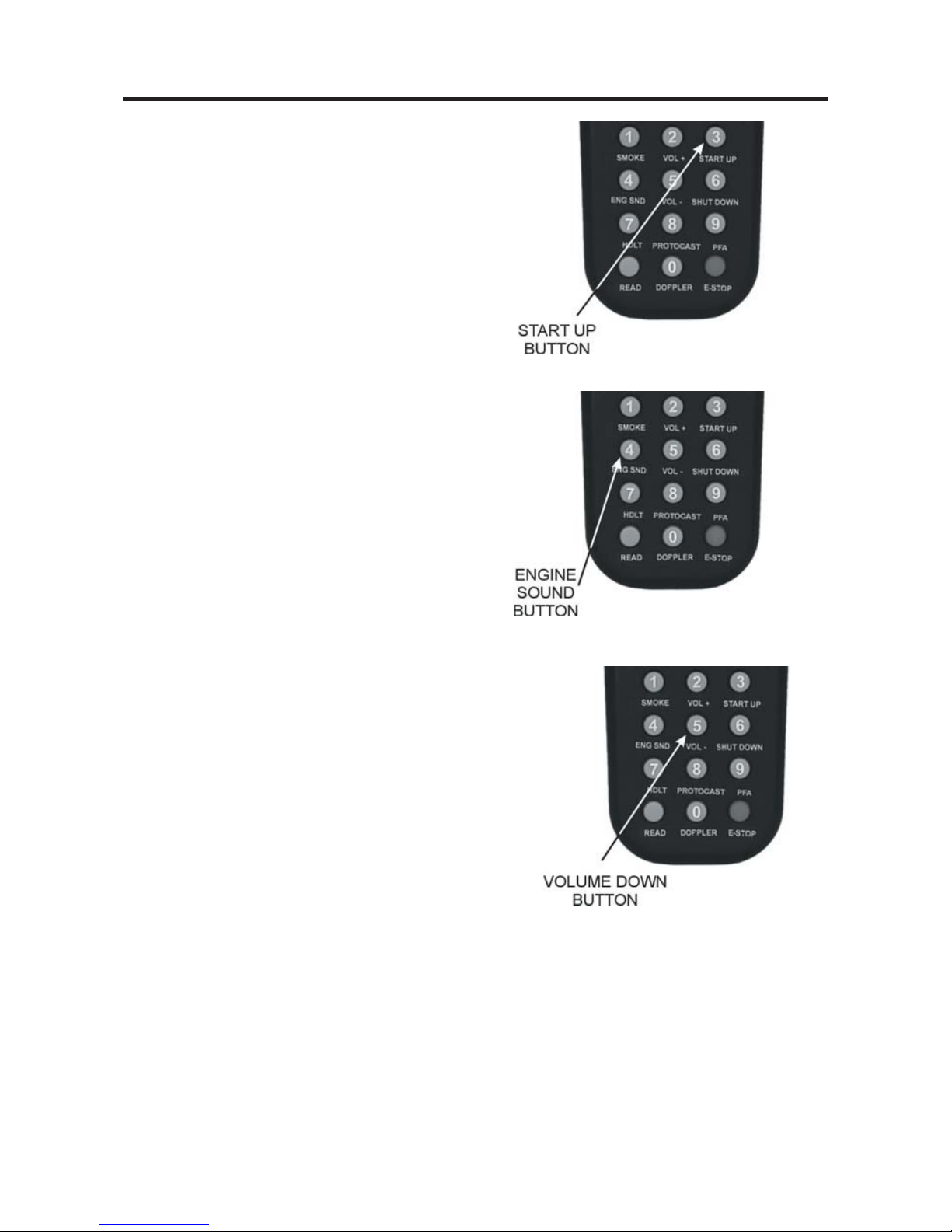
HDLT (7):
With the engine stopped, press this button
to turn headlight on and off (LCD will
show “Headlight = On” or “Headlight =
Off ”).
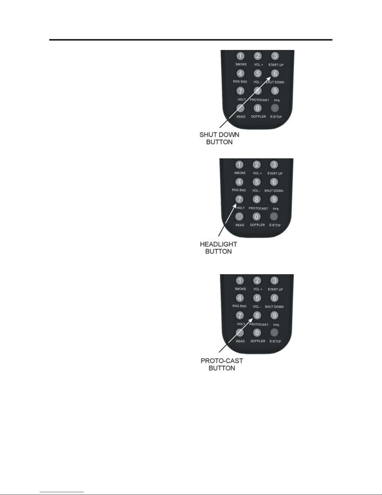
PROTOCAST (8):
To activate this feature, you must first
onnect an audio source to the DCS system.
1. Plug a male-to-male mini cable (1/8”
plug, like that used for the headset with a
portable CD/tape player or M.T.H. Item
No. 50-1009) first into the Proto-Cast port
of the TIU, then plug the other end of the
cable into your audio source’s headphone
jack or line-out jack.
2. Play the recording according to the audio
source’s instructions.
3. Press the “PROTOCAST” button to
play the recording through your engine.
When the Proto-Cast feature is enabled,
your regular engine sounds are silenced so
that the recording may be heard clearly. A
(C) appears on the LCD to indicate that
Proto-Cast is in use.
4. Press the button again to stop the feature
and return to normal engine sounds.
DCS Command System User’s Guide
One-Touch Locomotive Operation
30
DCS Tip: Because Proto-Cast sends such a large digital signal on the track, it is important that your track be clean when you run this feature. If you get popping and distortion while running Proto-Cast, please clean your track. The large digital signal also
means that playing the audio source too loudly can result in sound distortions; resolve
this by turning down the audio source volume.
DCS Tip: If you want to stop the PFAs from running before the sequence is complete,
press the PFA button again to turn the feature off.
PROTOCAST (8): (cont’d)
You can use Proto-Cast in only one
engine at a time (the active engineat the
time the feature is selected). Because
Proto-Cast uses a large share of the
microprocessor’s processing power in the
TIU, activating other features while running with Proto-Cast may cause interruptions in the audio.
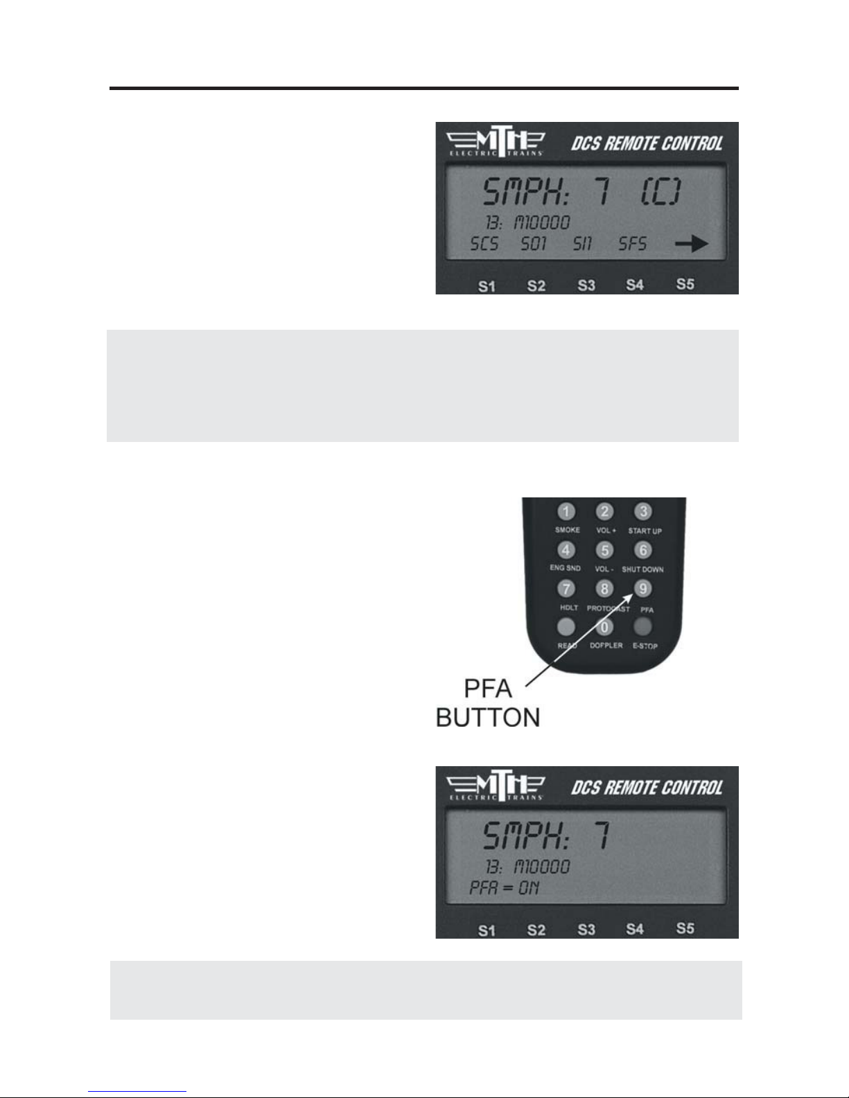
PFA (9):
1. Press this button to activate
Passenger/Freight Announcements (LCD
will show PFA = On” or PFA = Off).
2. Press the Direction button to stop the
train, then press it three more times, pausing for several second as described in your
engine’s conventional mode operating
instructions, to cycle through the PFA
sequences.
3. When the entire PFA script has run,
the bell will begin to ring and the engine
will pull out at the speed you had set
when you pressed the PFA button. If you
wish to run the engine at a slower speed
than when the PFA was activated, scroll
the SMPH to the desired speed. When
the engine begins to move, scroll the
SMPH one additional setting to lock in
the new slower speed.
DCS Command System User’s Guide

One-Touch Locomotive Operation
31
READ:
If you are adding or removing engines on
the track, press READ to update the
Active and Inactive Engine lists.
Alternately, you can change the active
status of each engine individually as
described in the “Selecting and Starting
the Locomotive” section in the “Quick
Start” chapter of this manual.
DOPPLER (0):
Press this button to activate the ProtoDoppler feature for one-time use (LCD
will show Doppler = On” or “Doppler =
Off ”). Engine sounds will initially drop,
then build to a peak before fading away.
Press the DOPPLER button again after
the effect has played to turn the feature
off and return the locomotive to normal
engine sounds.
See the “Doppler Setup” instructions in the
“Advanced Menu” portion of the “Menu
Operation” chapter(s) for how to set an engine to
play the Doppler effect every time it passes a certain place on your layout.
E-STOP (Emergency Stop):
This button instantly cuts power to all
tracks connected to your TIU(s). You
need to turn off power at the transformer,
power down the remote, return power,
and re-access and start-up engines like a
new session in order to continue operation.
Note: If the TIU is powered by an auxiliary
power supply, that power source must be
unplugged and plugged back in before the TIU
will reset.
DCS Command System User’s Guide

One-Touch Locomotive Operation
32
Feature Key
Features that start with:
S=Sound features
L=Light Features
M=Menu Features that you must then
setup
F=Function Features that you can turn
on or off
(See the full chart in Appendix A)
Softkeys (S1-S5):
Softkeys are designed to serve different
functions with different engines rather
than have a fixed function like the other
One-Touch keys. This flexibility is important because the wide variety of M.T.H.
engines has an equally wide range of
appropriate operating features. For
instance, a modern diesel has very different
operational features than an early
twentieth-century steamer.
The appropriate options for each engine
are displayed on the LCD as you control
that locomotive.
To activate softkey features:
-
Press softkeys S1-S4 to activate the fea-
ture listed directly above each button.
-
Use S5 to scroll though the softkey list
and access more softkey options for each
engine.
-
Press the softkey (S4) below “More” in
the fourth and final softkey screen to
access a list of additional softkey features
you can scroll and select with your thumbwheel.
DCS Command System User’s Guide

One-Touch Locomotive Operation
33
Softkeys (S1-S5): (cont’d)
To re-order softkey features:
It is possible to re-order the softkeys so
that the ones you use most often for a
given locomotive are at the top of its list.
1. Press the S4 softkey under “More” in
the fourth softkey screen to access the
complete scroll list of features.
2. Scroll until the arrow points to the
feature you want to move.
3. Press the S2 key under “Move”
4. Scroll to the softkey’s new location and
press the thumbwheel to place it there.
To delete softkey features:
If for some reason you want to delete a
softkey feature, you may. We encourage
you to do this sparingly; it is better to
reorder softkeys so that those you do not
use are at the bottom of the list.
1. Press the S4 softkey under “More” in
the fourth softkey screen to access the
complete scroll list of features.
2. Scroll until the arrow points to the
feature you want to move.
3. Press the S1 key under “Del”
4. Press the thumbwheel to confirm the
deletion.
DCS Command System User’s Guide

One-Touch Locomotive Operation
Softkeys (S1-S5): (cont’d)
To restore a deleted softkey:
Because softkeys are associated with an
engine rather than the system itself,
restoring a deleted softkey can only be
accomplished by deleting the engine it is
associated with and then readding the
engine.
See the System Menu section of the “Menu
Operation” chapter(s) of this manual for instructions on deleting and adding engines.
DCS Tip: The system is designed to
accommodate as many as 100 softkeys
per engine as we think of new features
to add.
Keep an eye on www.protosound2.com
or sign up for our free e-newsletter for
information on the growing softkey
chart.
34
DCS Command System User’s Guide

One-Touch Locomotive Operation
35
DCS Tip: The handheld MIC broadcasts its signals over an AM frequency to incorporate a realistic static sound one might encounter with radios. If you want static free
voice recordings, you should plug a microphone into the TIU and select that option
for your voice-over recording clips.
B/L:
Press this button to turn Backlight of
LCD screen ON & OFF. The backlight is helpful for low light, “nighttime” operation, but it will reduce battery life, so you may want to turn it
off when operating in a well-lit room.
MIC:
Press and hold this button to turn
Proto-Dispatch on. Release the button to turn Proto-Dispatch off. The
remote has a microphone built in, so
you can hold the MIC button down
and speak into the top of the remote
to project your voice through the
engine’s speaker. Your voice will be
laid over the engine sounds to simulate a real announcement. When the
button is depressed, “Dispatch” will
appear on the LCD screen.
Alternately, you can plug a microphone into the TIU’s “Proto-Dispatch
(Mic)” port and use that microphone.
DCS Command System User’s Guide

4
Chapter 4
Introduction.......................................... 37
Bell, Horn, Engine/Accent Volume.. 38
Proto-Whistle........................................ 39
Chuff Rate............................................. 40
Proto-Chuff........................................... 41
Cab Chatter............................................ 41
Brakes..................................................... 42
Clickty Clack.......................................... 42
Custom Sounds..................................... 43
Auto Coupler......................................... 47
Doppler Loop....................................... 48
External Mic.......................................... 49
Menu Operations - Sound
DCS Command System User’s Guide
36

DCS Command System User’s Guide
Menu Operations
The DCS system has four menu of
advanced operational options: Sound,
Control, System, Advanced. As with all
command mode controls, the menu sets
engine-specific features only for the
engine selected when the setting is made.
Although the features are advanced, they
are easy to access and set.
1. To access the menu list, press the
Menu button.
2. Use the thumbwheel to scroll so the
small arrow is beside the menu that you
want to access, and press down firmly on
the thumbwheel to select that menu.
3. Once you are in the menu, use the
thumbwheel to scroll through the features
lists. When the small arrow is beside the
desired feature, press firmly on the
thumbwheel to select.
4. Activate (or turn off) individual features
as described below.
37
DCS Tip: You can back out of a menu level at any time by pressing Menu to move
back one level at a time. To escape instantly to normal control, press ENG, ACC,
SW, or TR to return to that screen.
Menu settings are stored within the
engine. That means that a setting, such
as chuff rate or smoke volume, that is
selected in command mode remains at
that setting even on other layouts or in
conventional mode. If you will be operating in conventional mode later, be sure
to adjust all settings as you want them
before you leave DCS.

Menu Operations - Sound
38
Volume Controls (Bell, Horn, Engine Sounds, Accent)
Custom set the volume of the engine’s bell, horn, engine sounds, or accent sounds (e.g.,
passenger or freight sounds, cab chatter), independently of other engine sounds. The
selected sound will play when this feature is selected (except for Accent Sounds), so you
can hear it change volume as you make the adjustment.
Sound Menu:
Bell Volume
Horn Volume
Engine Sounds Volume
Accent Volume
Chuff Rate
Proto Chuff
Cab Chatter
Brakes
Clickity Clack
Custom Sounds
Auto Coupler
Doppler Loop
1. Use the thumbwheel to scroll up or
down and adjust the volume. As you
change the volume, you will see the lines
of the scroll bar move to the right (louder) or left (quieter), and a number on the
bottom of the LCD will tell you what percentage of maximum volume you hear.
You will also hear the change in the
selected sound’s volume relative to the
other engine sounds.
2. When you have chosen the desired volume, press firmly on the thumbwheel to
set that volume and return to the Sound
menu list.
DCS Command System User’s Guide

Menu Operations - Sound
Proto-Whistle
This feature allows you to use the thumbwheel to simulate the engineer's feathering or
“quilling” of the whistle/horn rope, producing a much more realistic whistle/horn
sound.
Proto-Whistle is not available on all DCS-equipped engines. This feature will only work
on those engines whose hardware is capable of utilizing the software feature. Therefore,
the softkey acronyms will not be visible on the DCS screen for locomotives not equipped
with the proper hardware. Downloading the sound set from a locomotive equipped with
the Proto-Whistle feature and loading it into an engine not factory equipped with the feature will not give the user the Proto-Whistle feature even though the Proto-Whistle softkey acronyms will appear on the DCS screen.
1. Select the Proto-Whistle-equipped
engine from your DCS remote.
2. Press the SPW softkey. It will highlight.
3. Your display will change to indicate that
Proto-Whistle is active.
4. Scrolling the thumbwheel up one click
at a time will produce the different whistle
tones.
5. Practice varying how fast you scroll up
and down on the thumbwheel and in no
time you'll be making whistle sounds just
like a real engineer!
6. To disable the feature and return to
controlling your engine press the SPW
softkey again.
Note: When Proto-Whistle is active your regular Whistle/Horn button is inactive as well as the
thumbwheel for controlling the speed of your engine.
DCS Command System User’s Guide
39

DCS Command System User’s Guide
Menu Operations - Sound
Chuff Rate
Change the number of chuffs per wheel revolution in your steam locomotives. Most
Proto-Sound 2.0 steam engines are set at two chuffs per revolution because that rate sounds
good even at fast toy train speeds. However, most steam engines prototypically have four
chuffs per revolution. You can choose the rate you want, up to 16 chuffs per rev.
1. One you select this feature, you will
see the numbers 1-4 on your LCD screen
over the S1-S4 softkeys, with an arrow
over the S5 key. Press S5 to scroll
through higher number options (up to 16
chuffs per rev) and back around to the
first screen.
2. When the desired number of chuffs
per revolution appears on the LCD, press the softkey (S1-S4) directly below the chuff
rate you want to set.
3. Once you see your selection highlighted on the LCD screen, press firmly on the
thumbwheel to confirm the selection and return to the Sound menu list.
Your engine’s puffing smoke is synchronized with the chuff rate, and the smoke puffs
will also change rate when you change the chuff rate.
40
DCS Tip: When operating a diesel or electric engine, setting the chuff rate to a value
between 1 and 8 will play the corresponding engine rev level.

DCS Command System User’s Guide
Menu Operations - Sound
Proto Chuff
Enable or disable automatic triggering of the engine’s Labor/Drift settings. Your engine
can be programmed to shift automatically into Labor/Rev Up (labored steam chuffing or
higher diesel revs and higher smoke output) when it senses an increase in speed or to go
into Drift/Rev Down (drift steam chuffing or lower diesel revs and lower smoke output)
when it senses a reduction in speed.
-
If you prefer that your engine not make
these changes, press the softkey under
“Off ” on the LCD.
-
To allow your engine to make these
automatic adjustments, press the softkey
under “Auto” on the LCD.
Press firmly on the thumbwheel to confirm the selection and return to the Sound
menu list.
Use of the one-touch LABOR REV UP/DRIFT REV DN rocker switch on the handheld overrides this menu setting. You will need to re-set it to Auto after exercising manual control.
Cab Chatter
When enabled, Cab Chatter (conversation among the cab crew) plays at random intervals
when the engine is stopped.
-
To disable cab chatter from playing, press
the softkey (S1) under the word “OFF.”
OR
-
To enable cab chatter, press the softkey
(S2) under the word “AUTO.”
Press firmly on the thumbwheel to confirm the selection and return to the Sound menu
list.
41

DCS Command System User’s Guide
Menu Operations - Sound
Brakes
When enabled, the Brakes feature triggers
the squealing brake sound effect automatically when you slow speed rapidly.
-
To disable squealing brakes from playing, press the softkey (S1) under the word
“OFF.”
OR
-
To enable squealing brakes, press the
softkey (S2) under the word “AUTO.”
Clickity Clack
When enabled, the sound set will automatically play the clickity-clack sounds of wheels
on rails when the engine moves at speeds greater than or above 30 smph and maintains
the same speed for 30 seconds or more. When you change the speed, the regular engine
sounds resume until the clickity clack conditions have again been met. The speed of the
sound effect varies with the train’s speed.
-
To disable clickity-clack sounds from
playing, press the softkey (S1) under the
word “OFF.”
OR
-
To enable clickity-clack sounds, press
the softkey (S2) under the word “AUTO.”
Press firmly on the thumbwheel to confirm the selection and return to the Sound menu
list.
42

Menu Operations - Sound
43
Custom Sounds
With DCS, you can record short sounds of your own making (the kids singing “Happy
Birthday,” a recording made from a scanner alongside a railroad yard, or a prototype
recording of a whistle you especially like) for playback through an engine’s speakers. The
sounds are captured inside the DCS TIU not the locomotive. This allows playback of
the sounds through any Proto-Sound 2.0 equipped locomotive when operating in
Command Mode.
There are 2 minutes and 54 seconds of
sound space available (broken down into 15
11-second blocks) in each TIU. You can
record multiple sounds of any length, as
long as the total time recorded does not
exceed 2:54. You can record or download
the sounds into your TIU, then play or erase
sounds at will.
In order to add custom sounds into the
TIU, you will need to connect the TIU to an
audio source. You have four choices of
audio sources;
1. The Proto-Dispatch microphone built
into the DCS Remote (designated as
Dispatch)
2. An External Microphone plugged into the
microphone input on the TIU (designated as
Microphone)
3. An External Music Source (like a CD or
tape player) connected to the TIU via a
1/8” mini-to-mini cable (designated as
Audio Jack)
4. Sounds already loaded onto a personal
computer via a 9-pin computer serial cable
attached to the TIU and PC (designated as
PC - requires spec.
DCS Command System User’s Guide

Menu Operations - Sound
44
Custom Sounds
Once the appropriate sound source has
been connected to the TIU, press the
Menu button on the DCS Remote and
select the Sound Menu, then follow the
steps below to record the sounds.
Record:
1. The LCD tells you how much time
remains available for new recording.
2. If you have more than one TIU on the
layout, select which TIU to record the
sound to.
DCS Tip: Your custom sound recording
can be one long segment. You may
choose to add multiple custom sound segments each of which will show up in the
pick list under the custom sound menu.
DCS Command System User’s Guide

Menu Operations - Sound
45
Custom Sounds: (cont’d)
Record: (cont’d)
3. Select Source for sound to be recorded
(Dispatch RF - DCS Remote MIC,
External Microphone, Audio Jack, PC).
4. Press S1 under REC to record the
sound.
5. Press S2 under STP to stop recording.
6. If you choose to play the sound right
away to review it, press S4 under PLY.
7. If you choose to save the sound to replay it later, press S3 under SAV. An
alphanumeric character set is displayed,
allowing you to name the sound. Use the
thumbwheel to scroll through the character set, and when the character you want
to type next is highlighted, press the
thumbwheel to select it. You may give the
sound a name up to 16 characters long.
Select the “D” at the end of the character
set to signify that you are done with this
function.
Play Sound
To play a sound at a later time, scroll and
press the thumbwheel to select the desired
sound from the list of saved sounds.
DCS Command System User’s Guide

Menu Operations - Sound
Note: Your engine comes equipped with some
pre-recorded custom sounds. Try softkeys
named S01-S10 to see what sounds you
already have.
Custom Sounds: (cont’d)
Edit Sound
Edit Sound Name
1. Scroll and press the thumbwheel to
select the sound you want to edit from the
list on the LCD.
2. An alphanumeric character set is displayed. Use the thumbwheel to scroll
through the character set, and when the
character you want to type next is highlighted, press the thumbwheel to select it.
You may give the sound a name up to 16
characters long. Select the “D” at the end
of the character set to signify that you are
done with this function.
Delete a Sound
1. Scroll and press the thumbwheel to
select the sound you want to delete from
the list shown on the LCD.
2. Press the thumbwheel one more time to confirm the deletion.
Delete All Sounds
To delete all recorded custom sounds, press the thumbwheel to confirm the deletion.
Update List
If you want to be able to play custom sounds that were recorded using a different handheld (e.g. if you want to share custom sounds at a club layout), press Update List to gain
access to all custom sounds saved into any TIU on the layout.
46
DCS Command System User’s Guide

Menu Operations - Sound
Auto Coupler
You can now elect to have the coupler
slack sounds play automatically every time
an engine pulls away from a stop, or only
when you press the SCS soft key.
1. Press MENU
2. Select SOUND
3. Scroll to AUTO COUPLER and press
Select .
4. Select either OFF or AUTO. AUTO
will enable the feature for ALL engines in
the remote.
5. Press the ENG button and select a
DCS engine.
6. Ensure the engine has been start-up.
7. Scroll the thumbwheel up to get the
engine moving and as soon as it pulls away
it will play the Coupler Slack sound.
8. Once the engine goes back to 0sMPH
then pulls away at any speed the sound will
play again. It will work this way on every
DCS engine in your remote until you shut
it off.
9. To turn the feature Off, repeat steps
1-3 and press the OFF softkey.
NOTE : This setting is a global setting, so when
you make this setting it will affect all engines in
the DCS Remote.
DCS Command System User’s Guide
47

DCS Command System User’s Guide
Menu Operations - Sound
Doppler Loop
This feature allows you to set the Doppler effect to play every time the programmed
engine passes a certain point on your layout. M.T.H. sound engineers measured this for a
scientifically accurate Doppler pitch change: the growing and fading of the sounds are
exactly what a scale person would hear as a scale train passed by.
1. Place the engine at the location on the
layout where you want the sound to peak
during Doppler sound. Press the S1 key
under “Beg” to highlight it and press the
thumbwheel to tell the engine to begin
measuring its Doppler loop. Run the
engine around the loop.
2. Stop the engine at the exact same location on the layout where you pressed “Beg.”
Press the S2 key under “End” to highlight it, then press the thumbwheel to stop measuring the loop.
3. To operate your Doppler Loop, make
sure the engine is where it was when you
pressed “Beg” and press the S3 key under
“On,” and run the engine like normal.
The sound effects will fade out as you pull
away from the peak spot on your layout
and will swell as you round the circle and
return to the peak spot. The locomotive
will continue to operate in consecutive
Doppler cycles until you press the S4 key
under “Off.” A (D) appears on the LCD
to indicate when Doppler is turned on.
48

DCS Command System User’s Guide
Menu Operations - Sound
Doppler Loop: (cont’d)
Note: Because there is no Global Positioning for model trains, the Doppler system measures distance,
not location on a layout. You must begin and end your setting and begin operation at the exact same
point on the layout, or the mis-measurement will cause the Doppler peak location to move over time. For
instance, if you stop programming the loop 5 inches short of where you started, the loop will be five inches short of your layout’s full route, and the Doppler peak will move by five inches on every trip around
the layout.
DCS Tip:
For small layouts:
There may not be enough room for the Doppler effect to fade completely to silence
between loops. You can turn down the master volume before running in Doppler mode
so that the engine sounds will fade completely.
For very large layouts:
You may have a large enough layout to program Doppler to play the loop more than
once as it circles your layout. To do this, divide your track very carefully into even segments (exact halves, thirds, or quarters), and program the Doppler effect to play for only
one of those segments. When you operate the train, the sound will play back-to-back as
it travels the track.
External Mic
-
When External Mic is active the (M) icon is lit on the LCD.
-
When External Mic is active the TIU CANNOT process any other
commands except the audio from the microphone.
-
You need to plug in a microphone into the Proto-Dispatch (Mic) jack
on the TIU.
-
You enable the above jack in the remote.
-
DO NOT forget to disable it once you are done using the mic.
49

5
Chapter 5
Smoke Output...................................... 51
Ditch Lights........................................... 52
Maximum Engine Speed..................... 52
Acceleration Rate................................. 53
Deceleration Rate................................. 53
Directional Control.............................. 54
Labored Smoke..................................... 54
Brake Boost.......................................... 55
Menu Operations - Control
DCS Command System User’s Guide
50

DCS Command System User’s Guide
Menu Operations - Control
Control Menu:
Smoke Volume
Ditch Lights
Max Speed
Acc Rate
Dec Rate
Dir Control
Labored Smoke
Smoke Volume
Adjust the output of the smoke unit.
1. Press the softkey (S1-S3) directly
below the desired smoke level: MIN
(Minimum), MED (Medium) or MAX
(Maximum). Most Proto-Sound 2.0
engines have the default set at Medium.
2. Once you see your selection highlighted on the LCD screen, press firmly
on the thumbwheel to confirm the
selection and return to the Control
menu list
It will take a couple of seconds before
you see the engine’s smoke output
change.
Caution: Be sure you always have smoke fluid in the engine when running with the
smoke unit on at any of the three levels. If you do not have smoke fluid, turn the smoke
unit off using the #1 key on the keypad. Check your smoke fluid level frequently when
running in MAX mode.
51

DCS Command System User’s Guide
Menu Operations - Control
Ditch Lights
Set the engine’s ditch lights (for engines
that are equipped with them) to one of
four settings.
1. Press the softkey under the desired setting: OFF, AUTO (turned on, flashing
only when you blow the horn), ON
(turned on all the time, no flashing), and
FLS (flashing all the time).
2. Once you see your selection highlighted on the LCD screen, press firmly on the
thumbwheel to confirm the selection and
return to the Control menu list.
Max Speed
You can set a maximum engine speed to
keep your locomotive from derailing as it
races through a tight curve (or keep the
kids or club members from getting carried
away and derailing your engine!).
Roll the thumbwheel down to lower the
maximum speed (the default is 120 smph)
to the setting you want, then press firmly
on the thumbwheel to confirm the selection and return to the Control menu list.
52

Menu Operations - Control
53
Acc Rate
Set your engine to accelerate in different
increments, ranging from 1 to 25. The
engine’s default acceleration rate is set low,
but you can set the engine to accelerate
much more quickly as you scroll the
thumbwheel. Set the rate low to avoid
derailing a long train of freight cars, or set
it high to keep up with the large speed
steps in other manufacturers’ engines.
Roll the thumbwheel to set the acceleration rate you want, then press firmly on
the thumbwheel to confirm the selection
and return to the Control menu list.
The “Boost” button on the remote boosts
your locomotive’s speed at the rate set
here.
Dec Rate
Set your engine to decelerate in different
increments, ranging from 1 to 25. The
engine’s default deceleration rate is set
low, but you can set the engine to decelerate much more quickly as you scroll the
thumbwheel. Set the rate low to avoid
derailing a long train of freight cars, or set
it high to keep up with the large speed
steps in other manufacturers’ engines.
Roll the thumbwheel to select the deceleration rate you want, then press firmly on
the thumbwheel to confirm the selection
and return to the Control menu list.
The “Brake” button on the remote slows
your locomotive’s speed at the rate set
here.
DCS Command System User’s Guide

Menu Operations - Control
54
Dir Control
Lock an engine into a direction by changing the direction cycle. Rather than the
default Forward/Reverse (F/R) cycle, you
can set it for a Forward/Forward (F/F) or
Reverse/Reverse (R/R) cycle. Remember,
in command mode there is no neutral.
Press the softkey (S1-S3) directly beneath
the direction cycle you choose.
Press firmly on the thumbwheel to confirm the selection and return to the
Control menu list.
Labored Smoke
Decide whether your engine’s
labored/drift chuffing and rev up/down
will be accompanied by a corresponding
change in the smoke level. The engine’s
default is to change the smoke level.
-
To disable labored smoke, press the
softkey (S1) under the word “OFF.”
OR
-
To enable labored smoke, press the
softkey (S2) under the word “AUTO.”
Press firmly on the thumbwheel to confirm the selection and return to the
Control menu list.
DCS Command System User’s Guide

Menu Operations - Control
55
Note: This setting is a global setting, so when
you make this setting it will affect all engines in
the DCS Remote
Brake/Boost
The Boost/Brake button can now function in two different ways, which you can
select from a menu. Select the “Stay”
option and your engine will remain at the
faster (Boost) or slower (Brake) speed
when you release the Boost/Brake button.
But select “Return” and your engine will
return to its previous speed when the
Boost/Brake button is released (as it does
with previous software versions).
1. Press MENU
2. Select CONTROL
3. Select BOOST/BRAKE
4. Press either STAY or RET. STAY holds
the engine speed at the indicated value
after releasing either the Boost or Brake
button. For example, if you have STAY
selected and you are currently going
15sMPH, pressing and holding the
BOOST button until you reach 25sMPH
then releasing the BOOST button will
make the engine run at 25sMPH. If you
had selected RET, the engine speed would
have gone back to 15sMPH (the speed
you started at when you pressed
Boost/Brake). This works the same way
with BRAKE.
DCS Command System User’s Guide

6
Chapter 6
Engine Setup......................................... 57
Track Setup............................................ 62
Switch Setup.......................................... 67
Accessory Setup.................................... 70
TIU Setup.............................................. 72
LCD Contrast....................................... 74
DCS Setup............................................. 74
Track Signal........................................... 75
Remote Setup........................................ 76
Set Remote Address............... 76
Remote Powerdown............... 77
Remote Back Up..................... 77
Quickset Speed........................ 78
Operating Mode...................... 79
Menu Operations - Systems
DCS Command System User’s Guide
56

DCS Command System User’s Guide
Menu Operations - Systems
System Menu:
Engine Setup
Track Setup
Switch Setup
Accessory Setup
Set Remote Address
TIU Setup
LCD Contrast
DCS Setup
Track Signal
Engine Setup
This menu is used to manage the engines
entered into the DCS system.
Add Engine
Add M.T.H. Engine
Wait until the LCD says the engine was
found and returns to the engine screen
addressing that engine. Because M.T.H.
features the SmartRead system, your
engine tells the TIU its name and you do
not need to enter any information in
order to add the engine.
If you want to add additional engines,
remove the previously added engine from
the track, place the new engine on the
track, and Add MTH Engine. You need
to complete these steps only once per
engine/handheld, when you first add it to
your system, not each time you place a
previously added engine on the track.
57

DCS Command System User’s Guide
Menu Operations - Systems
Engine Setup: (cont’d)
Add Engine
Add TMCC Engine
1. The LCD prompts you to name the
engine, and an alphanumeric character set
is displayed. Use the thumbwheel to
scroll through the character set, and when
the character you want to type next is
bracketed, press the thumbwheel to select
it. You may give the engine a name up to
16 characters long. Select the “D” at the
end of the character set to signify that you
are done with this function.
2. The LCD prompts you for the engine’s
TMCC number. Enter the number you
previously assigned the engine when you
entered it into the TMCC Command Base
(the address you use to address the engine
when you run it with the Cab 1®). This
number is unrelated to the number DCS
assigns the engine in the DCS engine list.
3. Next, select the TIU Address that is
connected to the TMCC Command Base.
58

Menu Operations - Systems
59
Note: The newly added TMCC engine will first appear in the Inactive Engine List. It must be
activated by selecting it before the engine will operate.
Note: Before you can add a TMCC engine, you must have the TMCC Command Base connected
to the TIU as described in the “Advanced Connection” section of the “Universal Locomotive and
Accessory Operation” chapter. See that chapter for instructions on operating TMCC engines via the
DCS remote.
Engine Setup: (cont’d)
Add Engine
Add TMCC Engine
4. DCS automatically assigns the engine
to a place in the engine list and takes you
to the engine screen.
DCS Tip: The < on the alphanumeric
character set is the back character, which
allows you to correct any typos you made.
The [blank] inserts a space.
DCS Tip: The LCD provides a shortcut
to the main Engine Setup screen. From
the active engine screen, press the softkey
under S/U to jump directly to Engine
Setup.
Note: Engines are stored in the handheld’s
memory, so if you want to run the same engine
with multiple handhelds, you must add that
engine to each handheld that will be used to control it.
DCS Command System User’s Guide

Menu Operations - Systems
60
Edit Engine
Each Proto-Sound 2.0 engine comes with a pre-assigned engine name (such as M10000)
and is added to the engine list in order, but you can choose to rename or renumber the
engines if you choose. For instance, if you have two of the same engine type or run at a
Club where other members have the same engine, you can rename them to distinguish
one from the other.
Edit Name
1. Scroll through the active engine list,
and when the arrow is beside the engine
you want to rename, press the thumbwheel to select it.
2. An alphanumeric character set is displayed. Use the thumbwheel to scroll
through the character set, and when the
character you want to type next is highlighted, press the thumbwheel to select it.
You may give the engine a name up to 16
characters long. Select the “D” at the end
of the character set to signify that you are
done with this function.
3. The LCD returns to the active engine
list, and you will see the new engine name
displayed on the LCD.
Note: Once you begin to change an engine
name via the character set, aborting the process
will leave the original name still intact.
DCS Command System User’s Guide

Menu Operations - Systems
61
Edit Engine: (cont’d)
Edit Engine Address
1. Scroll through the active engine list
and when the arrow is beside the engine
you want to renumber, press the thumbwheel to select it.
2. Scroll to an engine address/number
that you have not already assigned to
another engine (the LCD will show only
numbers that are not currently occupied).
Press the thumbwheel to select it and be
sent back to the System menu list.
Note: Editing an engine’s address will cause
the DCS system to delete all lash-ups associated
with the engine.
Delete Engine
1. Scroll until the arrow points to the
engine you want to delete and press the
thumbwheel to select it.
2. At the LCD prompt press the thumbwheel to confirm.
DCS Tip: If you wish to delete an entire
Lash-up, do it as though you were deleting
a single engine. For more information on
Lash-ups, see the Advanced Menu/Set
Lash-up section in this book.
DCS Command System User’s Guide

Menu Operations - Systems
62
Track Setup
This menu is used to manage conventional mode tracks that can be controlled via
the DCS handheld. The DCS system
automatically assigns track addresses to
the tracks wired to Variable channels 1
and 2 of TIU 1. You must enter and
address Variable channel tracks from additional TIUs and Fixed channel tracks
(controlled by a Z-4000 remote receiver)
from any TIU manually, as described
below.
Add Track
Add TIU Track
via Variable channels only)
1. Select the TIU connected to the track
you want to add by scrolling through the
list (TIU 1-5—there is no need to complete this step if you are using only one
TIU; the system enters these tracks automatically) and pressing the thumbwheel.
2. Select the track you want to add
For instructions on running a conventional mode engine on a Variable track, please
see the “Universal Locomotive Control:
Conventional Mode” section of the
“Universal Locomotive and Accessory
Operation” chapter.
(use for tracks wired
DCS Command System User’s Guide

Menu Operations - Systems
63
Track Setup: (cont’d)
Add Track: (cont’d)
Add TIU Track: (cont’d)
3. The LCD prompts you to name the
track, and an alphanumeric character set is
displayed. Use the thumbwheel to scroll
through the character set, and when the
character you want to type next is bracketed, press the thumbwheel to select it. You
may give the track a name up to 16 characters long. Select the “D” at the end of
the character set to signify that you are
done with this function.
Add Z4K Track
(use for tracks wired via Fixed channels
and controlled with a Z-4000® remote
receiver only)
1. Ensure the power to the Z-4000 transformer is OFF.
2. Connect the RJ-11 jack on the receiver
to the back of the Z-4000 transformer
you wish to use. There is no external
power for the receiver; it receives its
power from the transformer.
3. Go through DCS System menu/Track
Setup to reach Add Z4K Track.
4. Select Z-4000 address (Z4K1-Z4K3)
to tell the DCS handheld which Z-4000
remote receiver to address.
DCS Command System User’s Guide

DCS Command System User’s Guide
Menu Operations - Systems
Track Setup: (cont’d)
Add Track: (cont’d)
Add Z4K Track
5. Look at the back of the Z-4000 to see
which is track 1 and which is track 2.
Scroll within the LCD to the track you
want to run and press the thumbwheel to
select.
6. The LCD prompts you to name the
track, and an alphanumeric character set is
displayed. Use the thumbwheel to scroll
through the character set, and when the
character you want to type next is bracketed, press the thumbwheel to select it. You
may give the track a name up to 16 characters long. Select the “D” at the end of
the character set to signify that you are
done with this function.
7. Follow the LCD’s prompt to “Turn on
Z4K. When PG PG appears (in the
transformer’s LED display) press E-stop
(on the DCS handheld).”
For instructions on running a conventional mode
engine on a Z-4000 track, please see the
“Universal Locomotive Control: Conventional
Mode” section of the “Universal Locomotive and
Accessory Operation” chapter.
64

Menu Operations - Systems
65
Track Setup: (cont’d)
Edit Track:
Track Name
1. Scroll to the track whose name you
wish to edit and select it with the thumbwheel.
2. The LCD prompts you to name the
track, and an alphanumeric character set is
displayed. Use the thumbwheel to scroll
through the character set, and when the
character you want to type next is bracketed, press the thumbwheel to select it. You
may give the track a name up to 16 characters long. Select the “D” at the end of
the character set to signify that you are
done with this function.
Reorder Tracks
1. Scroll to the track you want to relocate
within the list of tracks and press the
thumbwheel to select.
2. Scroll through the list of tracks to the
new location for that track, and press
thumbwheel to complete the move.
DCS Command System User’s Guide

DCS Command System User’s Guide
Menu Operations - Systems
Track Setup: (cont’d)
Delete Track
1. Scroll until the arrow points to the
track you want to delete and press the
thumbwheel to select it.
2. At the LCD prompt press the
thumbwheel to confirm.
66

Menu Operations - Systems
67
Note: The LCD will only display the
number of AIUs currently connected (ie: if only
2 AIUs are connected, the display will read
AIU1 and AIU2.
Switch Setup
This menu is used to manage switches (turnouts) that can be controlled via the DCS
handheld. An AIU (Accessory Interface Unit, Item No. 50-1004) is required for remote
control of switches.
Add Switch
1. Wire the switch into the AIU as
shown in the AIU user’s manual and
your track’s instructions.
2. Select which TIU (if you are using
more than one), and the previously
connected AIU, to which the switch is
added to. (See the TIU Setup section
later in this chapter for how to number TIUs.)
3. Select which AIU the switch is
added to. To determine the AIU’s
number, simply count out from the
TIU. For instance, if you have three
AIUs, the one connected directly to the
TIU is AIU1, the one connected directly to AIU1 is AIU2, and the one connected directly to AIU2 is AIU3.)
4. Select the AIU port (SW1-SW10)
the switch is wired into.
5. The LCD prompts you to name the
switch, and an alphanumeric character
set is displayed. Use the thumbwheel
to scroll through the character set, and
when the character you want to type
next is bracketed, press the thumbwheel
to select it. You may give the switch a
name up to 16 characters long. Select
the “D” at the end of the character set
to signify that you are done with this
function.
DCS Command System User’s Guide

Menu Operations - Systems
68
Switch Setup: (cont’d)
Edit Switch
Switch Name
1. The complete list of switches (for all
TIUs and AIUs) appears on the LCD.
Scroll to the one you want to rename and
press the thumbwheel to select.
2. The LCD prompts you to name the
switch, and an alphanumeric character set
is displayed. Use the thumbwheel to
scroll through the character set, and when
the character you want to type next is
bracketed, press the thumbwheel to select
it. You may give the switch a name up to
16 characters long. Select the “D” at the
end of the character set to signify that you
are done with this function.
Switch Path
If you change the TIU or AIU a particular accessory is wired to (for instance if
you add TIUs and AIUs as a layout
expands), you must tell the DCS system
its new path. The DCS System will activate whichever switch is wired into the
path listed, whether it is the original
switch or not.
1. Wire the switch into the new AIU
port.
2. Follow the System Menu to Switch
Path, so that the complete list of switches
(for all TIUs and AIUs) appears on the
LCD. Scroll to the one you want to repath and press the thumbwheel to select.
DCS Command System User’s Guide

Menu Operations - Systems
69
Switch Setup: (cont’d)
Edit Switch
Switch:
3. Select which TIU the switch is added to.
4. Select which AIU the switch is added to.
5. Select the AIU port (SW1-SW10) the
switch is wired into.
Naming Tip: Because you may have
several switches and accessories of the
same type (multiple O-72 switches, several block signals, etc.), you should choose
their names carefully. Otherwise, you
might not be able to distinguish one
from the other in the heat of operations.
Try naming them for landmarks that are
near them on the layout or for the corner
of the train room they are nearest.
“Diner switch” for a switch by Mel’s
Diner will be far easier to recognize on
the fly than “O-72 no 3.”
(cont’d)
Delete Switch
1. Scroll until the arrow points to the
switch you want to delete and press the
thumbwheel to select it.
2. At the LCD prompt press the thumbwheel to confirm.
DCS Command System User’s Guide

Menu Operations - Systems
Accessory Setup
This menu is used to manage accessories that can be controlled via the DCS handheld.
An AIU (Accessory Interface Unit, Item No. 50-1004) is required for remote control of
accessories. The instructions are very similar to those found under the Switch Setup section previously found in this chapter.
Add Accessory
1. Wire the accessory into the AIU as shown in the AIU user’s manual and your
accessory’s instructions.
2. Select which TIU the accessory is added to (See the TIU Setup section later in this
chapter for how to number TIUs.)
3. Select which AIU the accessory is added to. To determine the AIU’s number, simply
count out from the TIU. For instance, if you have three AIUs, the one connected directly to the TIU is AIU1, the one connected directly to AIU1 is AIU2, and the one connected directly to AIU2 is AIU3.)
Note: The TIU will only display the number of AIUs currently connected (ie: if only 2 AIUs are
connected, the display will read AIU1 and AIU2.
4. Select the AIU port (ACC1-ACC10) the accessory is wired into.
5. The LCD prompts you to name the accessory, and an alphanumeric character set is
displayed. Use the thumbwheel to scroll through the character set, and when the character you want to type next is bracketed, press the thumbwheel to select it. You may give
the accessory a name up to 16 characters long. Select the “D” at the end of the character
set to signify that you are done with this function.
Edit Accessory
Accessory Name
1. The complete list of accessories (for all TIUs and AIUs) appears on the LCD. Scroll
to the one you want to name or rename and press the thumbwheel to select.
2. The LCD prompts you to name the accessory, and an alphanumeric character set is
displayed. Use the thumbwheel to scroll through the character set, and when the character you want to type next is bracketed, press the thumbwheel to select it. You may give
the accessory a name up to 16 characters long. Select the “D” at the end of the character
set to signify that you are done with this function.
70
DCS Command System User’s Guide

Menu Operations - Systems
Accessory Setup: (cont’d)
Edit Accessory
Accessory Path
If you change the TIU or AIU a particular accessory is wired to (for instance if you add
TIUs and AIUs as a layout expands), you must tell the DCS system its new path. The
DCS System will activate whichever accessory is wired into the path listed, whether it is
the original accessory or not.
1. Wire the accessory into the new AIU port.
2. Follow the System Menu to Accessory Path, so that the complete list of accessories
(for all TIUs and AIUs) appears on the LCD. Scroll to the one you want to re-path and
press the thumbwheel to select.
3. Select which TIU the accessory is added to.
4. Select which AIU the accessory is added to.
5. Select the AIU port (ACC1-ACC10) the accessory is wired into.
Delete Accessory
1. Scroll until the arrow points to the accessory you want to delete and press the thumbwheel to select it.
2. At the LCD prompt press the thumbwheel to confirm.
DCS Command System User’s Guide
71

Menu Operations - Systems
72
Note: If for some reason you want to replace
one TIU with another, afteradding the new
TIU, readdress the TIU you want to replace to
the new TIU address. This will prevent you
from having to re-enter all accessories, etc., from
the beginning.
TIU Setup
This menu is used to manage TIUs that
can be controlled via the DCS handheld.
TIUs are assigned addresses 1-5 (up to
five TIUs per handheld). The system
automatically assigns every TIU to address
1 when power to the TIU is first applied.
If adding additional TIUs, you must readdress the current TIU if it is still listed
as TIU 1 to the next open TIU Address
Number. If you fail to re-address the
original TIU from TIU Address 1 before
hooking up and powering the new TIU, all
associations (AIUs and Locomotives) of
the original TIU will be lost. Follow the
Edit TIU Address directions below.
Edit TIU Address
1. Scroll and press to select the current
address of the TIU you want to readdress.
2. The LCD will list the available TIU
addresses. Press the thumbwheel to select
the new address number
Delete TIU
1. Scroll to the address number of the
TIU you want to delete from your system
and press to select it.
2. The LCD will issue a warning that all
items associated with that TIU (including
tracks, AIUs, and accessories and switches
connected to those AIUs) will be lost.
Press the thumbwheel to confirm the
deletion.
DCS Command System User’s Guide

Menu Operations - Systems
Super TIU
This function allows the system to control
more than one TIU in a contiguous loop.
It creates a temporary global address for all
TIUs currently being used. This global
address eliminates the need for the user to
control access to the different TIUs as
locomotives enter sections of the layout
controlled by those TIUs.
On these multiple TIU layouts, each TIU must have its own, unique TIU address (1 - 5).
Each TIU must then be accessed via the remote and changed to a Super TIU. Simply
select the Super TIU option under TIU setup for the TIU you are currently editing.
Once all the TIUs on the layout have been changed to a Super TIU, an engine can move
from section to section of the layout seemlessly.
Super TIU Setup Example (Using 3 TIUs)
1. Reset all remotes and TIUs.
2. Set TIU addresses to 1,2, and 3.
3. Set remote addresses (if using multiple remotes) 1,2, and 3.
4. Add TIU’s 2 & 3 to each remote.
5. If using separate remotes, set all 3 TIUs to super mode IN EACH OF THE THREE
REMOTES.
6. Add engines to each remote (use same TIU to avoid lash-up address conflicts).
7. Build lash-ups (again, on same TIU tracks), thereafter, run across multiple TIUs.
Note: Certain DCS functions that are controlled by a specific TIU (custom sounds, Proto-Cast,
Proto-Dispatch, etc.) will only remain active through a selected engine as long as that engine is in the section of the layout controlled by that TIU. Once the engine leaves that section of the layout and “hands”
its control off to another TIU, the above effects will cease to play.
DCS Command System User’s Guide
73

DCS Command System User’s Guide
Menu Operations - Systems
Reset TIU
Select this option to reset the TIU to its
factory default settings.
LCD Contrast
Use the thumbwheel to adjust the contrast
between the LCD background and lettering, and press the thumbwheel to select.
DCS Setup
This function allows you to turn off the
DCS signal to a given channel, should you
ever choose to do so (ie: so that you can
operate a Ps2 engine as a conventional
engine).
Note: The presence of the DCS signal on the
track does not interfere with conventional or
TMCC operation, so you do not need to do this
when you run conventional or TMCC engines.
1. Select the TIU channel you want to set
up from the list shown.
2. Press the softkey under ON (S1), OFF
(S2), AON (All On) (S3), AOF (All Off)
(S4) or FXD (Fixed Output) (S5) to select
the desired setting.
3. Press the thumbwheel to confirm the
setting.
74
Note: The FXD settng allows users to configure a Variable Track as a Fixed Output track.
Whatever voltage is sent into the channel is sent out to the track. Users will not have to manually
dial up the output voltage.

Menu Operations - Systems
75
Track Signal
DCS allows you to test the power distribution to your track, so you can find and
repair weak spots.
1. Go to the active engine list and select
the Proto-Sound 2.0 engine you will use
to test the track signal.
2. Scroll through the softkey list and
select the softkey under More.
3. Scroll down to Track Signal in the
complete softkey list.
4. After about a second the LCD will
show you the track quality in the form of
a number that gets updated once per second. For most operations, a number of 5
or higher is strong enough to run your
layout. For especially data intensive operations, such as Proto-Cast and sound set
downloads, your may find that a higher
number is required.
5. When you are ready to stop checking
track signal and return to normal operations, press and hold the S5 softkey under
END for 1-2 seconds until the LCD
returns to the active engine screen.
DCS Command System User’s Guide

Menu Operations - Systems
Note: If multiple users want to share engines, each engine must be read into each remote.
Remote Setup
Edit Remote Address
When multiple users are addressing the same TIUs (on a Club layout, for instance), you
may need to give each handheld a unique identification number to avoid interference with
each other’s communications.
Scroll the thumbwheel to the remote address you want to assign to your handheld, and
press to select.
Reset Remote (not in Code 2.0)
Select this option to reset the remote to the factory settings.
Remote Messages
Setting Remote Messages to OFF will
turn off the messages displayed when
most functions are activated (Smoke,
Master Volume, etc). It will not
disable the display of errors messages like
Out of RF Range and Check Track.
The default for Remotes Messages is
ON."
Remote Powerdown
Allows you to adjust the power down
(sleep) timer on your DCS Remote from
1-60 minutes.
1. Press MENU
2. Select SYSTEM
3. Select REMOTE SETUP
76
DCS Command System User’s Guide

Menu Operations - Systems
Remote Powerdown: (cont’d)
4. Select REMOTE POWERDOWN
5. Use the thumbwheel to display the value
you wish to set as your DCS Remote's
sleep timer (from 1-60 minutes).
6. Press the thumbwheel to select the
value. When pressed the remote will say
“NEW VALUE SAVED”.
Remote Back up
For more information on Remote Back Up
please visit our website at:
http://www.protosound2.com/
On the DCS Software Updates table
download:
DCS Remote Clone Software Version 1.0
DCS Command System User’s Guide
77

DCS Command System User’s Guide
78
Menu Operations - Systems
Quickset Speed
Press the thumbwheel, enter a desired
speed on the keypad, then press the
thumbwheel again. Your engine will
smoothly accelerate or decelerate to that
speed setting. Observe speed restrictions
on your railroad like a real engineer!
1. Press MENU
2. Select SYSTEM
3. Select REMOTE SETUP
4. Select QUICKSET SPEEED
5. Select ON or OFF
6. When ON is selected you are able to
send any speed you want to an engine
quickly.
7. Press the ENG button and then select
a DCS-equipped engine from the list.
8. Press down on the thumbwheel (Select)
and you will see the display change to
indicate “QUICKSET SPEED”.
9. Using the numeric keypad enter the
speed you want that engine to go.
10. Press the thumbwheel down again
(Select) and you will see your engine
moving at the speed you selected.

DCS Command System User’s Guide
79
Menu Operations - Systems
Operating Mode
This allows you to select whether you want
the DCS Remote to operate in Speed Mode
or Normal Mode. The difference is that
Speed Mode allows for much faster
response times and does not require a
response from the TIU before moving on
to the next command.
1. Press MENU
2. Select SYSTEM
3. Select REMOTE SETUP
4. Select OPERATING MODE
5. Select SPEED or NORMAL
Because Speed Mode takes advantage of
known good RF and track communication
it provides the operator with much faster
response. Speed Mode works by not requiring the TIU to respond back to the Remote
for every command sent. As a result, some
functions may not work properly. They
include:
READ, Track Signal, Info
If you experience what appears to be a loss
of communication with the TIU or the
engine you may need to switch the
Operating Mode back to Normal."

7
Chapter 7
Create Lash-up...................................... 81
Route Setup........................................... 89
Scene Setup............................................ 92
Record/Playback................................... 94
Reset Engine.......................................... 96
Information........................................... 97
AC Input................................................ 97
Menu Operations - Advanced
DCS Command System User’s Guide
80

DCS Command System User’s Guide
Menu Operations - Advanced
Advanced Menu:
Create Lash-up
Route Setup
Scene Setup
Record/Playback
Reset Engine
Information
AC Input
Create Lash-up
You can create and name a lash-up to
operate two or more engines essentially as
a single engine. Create Lash-up automatically sets each engine’s direction, sounds,
lights and couplers to behave as appropriate for that lash-up (e.g. directional lighting acts as appropriate for the lash-up, and
when you press the button to open the
coupler, only the coupler at the rear end
of the lash-up will fire).
Add Engine
1. Press READ to make sure all the
engines you want to add are active.
2. Enter the Create Lash-Up menu, scroll
to Add Engine and press the thumbwheel
to see a list of all active engines.
3. Scroll to the engine you want to add to
the lash-up and press the thumbwheel.
81

Menu Operations - Advanced
82
Create Lash-up
Add Engine (cont’d)
4. At the Select Position prompt, select
whether that engine will be the head, middle, or tail engine.
5. At the Select Direction prompt, select
whether that engine will face forward or
reverse.
6. Add the next engine.
Note: You must have at least a head and tail
engine to complete a lashup.
7. When you have added all the engines
in that lash-up, Scroll to Lash-up Name
and an alphanumeric character set is displayed. Use the thumbwheel to scroll
through the character set, and when the
character you want to type next is bracketed, press the thumbwheel to select it. You
may give the lash-up a name up to 16
characters long. Select the “D” at the end
of the character set to signify that you are
done with this function.
The lash-up will now appear on the active
engine list as a single engine, and (L) will
appear on the LCD to indicate when the
lash-up is in operation. Operate it as if it
were a single engine.
DCS Command System User’s Guide

Menu Operations - Advanced
83
DCS Tip: If you want to separate one
engine from a lash-up during operations,
activate and operate (press the startup
button) the individual engine from the
engine screen. This will render the lashup inactive. To restore the engine to the
lash-up, re-couple it and reactivate the
lash-up from the engine list. Note that
any special non-default settings you
made to the lash-up will be lost when
you do this.
Create Lash-up
Delete Engine
Use to delete an engine from a Lash-up
during the creation process.
1. Scroll and press to select the lash-up
from which you want to delete an engine.
2. Scroll and press to select the engine to
be deleted.
3. When prompted to confirm the dele-
tion, press the thumbwheel.
To delete an entire Lash-up, see the System
Menu/Engine Setup/Delete Engine section in
this chapter.
The lash-up remains in DCS memory
until you delete it or any of the engines
that make up the lash-up. You can continue to operate your engines individually
or even as part of another lash-up by
placing that engine/lash-up on the active
engine list and operating it as normal.
Be careful not to attempt to run a single engine in
more than one lash-up or alone and as part of a
lash-up at the same time.
Note: If you select and attempt to operate a
lash-up when the engines are not coupled together,
they will each individually power up and follow
the lash-up commands, wherever they are on the
layout.
DCS Command System User’s Guide

DCS Command System User’s Guide
Menu Operations - Advanced
Improved TMCC® Control
Create TMCC Lash-up
Select an individual engine in a lash-up,
change its settings (lighting, sounds, or
smoke, for example), and those changes
will be retained when you go back to controlling the lash-up.
1. Ensure the engines you wish to add to
the Lash-up are in the ACTIVE LIST on
the Remote.
2. Ensure the TMCC Command Base is
powered on, connected to the TIU you
use to talk to TMCC engines, and connected to the outer rail of your track from
the “U” post on the Command Base.
3. Apply track power
4. Press MENU
5. Select ADVANCED
6. Select CREATE LASH-UP
7. Select TMCC LASH-UP
8. Select ADD ENGINE
84

Menu Operations - Advanced
85
Create TMCC Lash-up: (cont’d)
9. Scroll through your engine list to grab
the engine you want to place into the lashup.
10. Select HEAD, MIDDLE, or TAIL
depending upon which engine you want to
add first. It's easiest to start with the Head
engine and then work your way to the Tail
engine.
11. Select FORWARD or REVERSE for
the direction the engine is facing in the
Lash-up (the engine must already be facing
this way on the track).
12. Repeat steps 7-9 for the remaining
engines you want to add to the lash-up.
13. If you make a mistake on adding an
engine you can use the DELETE
ENGINE function to select the engine to
delete from the lash-up.
14. Once you have completed adding
engine in the position and which direction
they are facing you can now give your new
lash-up a name. Select LASH-UP NAME.
DCS Command System User’s Guide

Menu Operations - Advanced
86
Create TMCC Lash-up: (cont’d)
15. Enter the name of the lash-up in 16
characters or less and then select the “D”
character at the end of the list to tell the
remote you're done. If you make a mistake
while entering the lash-up name you can
use the “<” character to backspace and
correct the text.
16. Now that you have completed the
lash-up building process your engines will
power on and then each one will sound it's
horn/whistle three times to signify that it's
received the lash-up data and is ready to
operate. Once all the engines in the lashup have sounded their horn/whistle the
new lash-up will appear in your DCS
remote in the INACTIVE ENGINE list.
Note: When TMCC lash-ups are built in the
DCS Remote they are placed at locations 91-99
in the DCS Remote.
17. Press the ENG button and scroll
down to the new lash-up you built and
press the thumbwheel (Select).
18. The new lash-up will be displayed in
the LCD.
Your new TMCC lash-up is now ready to
operate.
19. To delete a TMCC lash-up press the
MENU button (ensure track power is
applied).
20. Select SYSTEM.
DCS Command System User’s Guide

Menu Operations - Advanced
87
Create TMCC Lash-up: (cont’d)
21. Select ENGINE SETUP.
22. Select DELETE ENGINE.
23. Scroll to the TMCC lash-up you want to
delete and press the thumbwheel (Select).
24. The engines in the lash-up will sound
their whistle/horn 1 time to indicate they
are now individual engines.
Create a TMCC lash-up using the
same procedure you use to create DCS
lash-ups. It's a much easier process than
using a CAB-1.
If you want to control any of the individual
engines that make up a TMCC lash-up you
can go into the Inactive Engine list and
select the engine, this will make it Active.
Scroll up to the Active engine list and select
the engine, press Start-Up and now you have
full control of that TMCC engine.
When adding/deleting a TMCC lash-up
ensure you have track power applied and the
TIU-TMCC cable connected as well as the
track connection from the TMCC
Command Base connected to the outer rail
of the track.
When TMCC lash-ups are created they are
placed at DCS locations 91-99. Should an
engine exist at one or more of those locations the remote will place the TMCC lashup in the next available position. If all
positions are taken up (91-99) then you will
need to move one or more of the engines at
91-99 to allow room for your lash-up. Just like TMCC engines, your TMCC lash-ups will
not operate under ALL mode.
You cannot add or edit TMCC engine addresses to 91-99 as these are reserved for DCS
Proto-Sound 2.0 engines and TMCC lash-ups. You are free to add or edit TMCC engines
to addresses 1-90.
DCS Command System User’s Guide

Menu Operations - Advanced
DCS Lash-up Defaults:
Smoke units in all engines are turned OFF.
Head Engine:
-
All sounds fully operational.
-
All lights fully operational except the back-up light will not turn on when the lash-up is
‘ in reverse.
-
Only the front coupler (if the engine has one) is operational.
Middle Engines:
-
Only engine sounds are operational.
-
No lights are operational.
-
No couplers are operational.
Tail Engine:
-
Only engine sounds are operational.
-
Directional lighting is operational. (i.e. if the engine faces the rear, the headlight will be
on when the lash-up is in reverse, but if the engine faces the front, the back-up light
comes on in reverse.)
-
Only the coupler at the rear of the lash-up (whether it is the individual engine’s front
or rear coupler) is operational.
Over-riding DCS Lash-up Defaults:
To over-ride lash-up defaults in particular engines, select the individual engine and make
adjustments to it. For instance, to turn the horn on in a middle engine, select that engine
from the inactive engine list. Next, select the same engine from the active list, enter its
sound menu and turn the horn volume from 0 (the default set by Create Lash-up) to the
level you want.
To change a feature for the entire lash-up (e.g. to turn the smoke on), select the lash-up
from the active engine list and change the feature as described in these instructions.
Note: every time you start a lash-up for a new session, the factory-set lash-up defaults are enabled.
88

Menu Operations - Advanced
Note: your TIU and turnouts must be connected through an AIU for this feature to
work. See the AIU Operator’s Manual for
instructions on wiring, mapping, and naming
switches.
Route Setup
The Set Route feature allows you to program all necessary turnouts to switch into
the correct position for a given route. For
instance, if you need to move an engine
from point A to point B (e.g. if you’re
switching cars in a yard), you can program
a route that will correctly position all the
turnouts along the way for you.
The DCS system allows you to set up to
15 routes per handheld, and you can control up to 250 turnouts per route. This
means that a club that operates with four
DCS handhelds, for example, can set a
total of 60 routes (15 routes for each of
the four handhelds), but that a given route
can be activated only from the handheld
into which it is entered.
Create Route
1. Name the route. An alphanumeric
character set is displayed; use the thumbwheel to scroll through the character set,
and when the character you want to type
next is bracketed, press the thumbwheel
to select it. You may give the route a
name up to 16 characters long. Select the
“D” at the end of the character set to signify that you are done with this function.
2. You are given a list of all the switches
entered into the DCS system. Scroll the
thumbwheel until the arrow is beside the
switch you want to add to the route and
press the position arrow (S1 or S2) to
indicate whether the turnout should
switch straight or curved when you run
the route.
89

Menu Operations - Advanced
90
Route Setup
Create Route:
3. Add the next switch.
4. To change the direction of a switch
you added, you must remove the switch
and re-add it and press the correct directional arrow(S1 or S2) you desire.
5. To remove a switch you added by mistake, press the softkey (S3) under REM.
6. When you have finished adding a
route, press the softkey (S4) under
DONE.
The route will appear in the switch list
accessed by pressing the SW button, just
as though it were a normal switch.
Activate it by scrolling to it and pressing
the S4 Softkey marked ACT.
(cont’d)
Delete Route
1. The LCD shows the switch list. Scroll
to the route you want to delete and press
the thumbwheel.
2. When prompted to confirm the deletion, press the thumbwheel a second time.
DCS Command System User’s Guide

Menu Operations - Advanced
91
Edit Route
Edit Name
1. The LCD shows the switch list. Scroll
to the route you want to edit and press
the thumbwheel.
2. An alphanumeric character set is displayed; use the thumbwheel to scroll
through the character set, and when the
character you want to type next is bracketed, press the thumbwheel to select it. You
may give the route a name up to 16 characters long. Select the “D” at the end of
the character set to signify that you are
done with this function.
Edit Switches
1. The LCD shows the switch list. Scroll
to the route you want to edit and press
the thumbwheel.
2. The LCD will return you to the switch
list to change which switches are in that
route. To add or delete a switch from the
route select the appropriate softkey
(S1 - S3) setting you want.
3. When you have finished editing the
route, press the softkey (S4) under
DONE.
DCS Command System User’s Guide

Menu Operations - Advanced
92
Scene Setup
Set Scene works essentially the same way
as Set Route, except that this feature programs accessories. If you want certain
lights, signals, or other accessories to
operate in tandem, for instance when you
operate a particular train or industry, you
can program them here.
The DCS system allows you to set up to
15 scenes per handheld, and you can control up to 250 accessories per scene.
Note: your TIU and accessories must be connected through an AIU for this feature to work.
See the AIU Operator’s Manual for instructions
on wiring, mapping, and naming accessories.
Create Scene
1. Name the scene. An alphanumeric
character set is displayed; use the thumbwheel to scroll through the character set,
and when the character you want to type
next is bracketed, press the thumbwheel
to select it. You may give the scene a
name up to 16 characters long. Select the
“D” at the end of the character set to signify that you are done with this function.
2. You are given a list of all the accessories entered into the DCS system.
Scroll the thumbwheel until the arrow is
beside the accessory you want to add to
the scene and press the On button to
indicate that the accessory should activate
when you run the scene.
3. Add the next accessory.
DCS Command System User’s Guide

Menu Operations - Advanced
93
Scene Setup
Create Scene:
4. To remove an accessory you added by
mistake, press the softkey (S3) under
REM.
5. When you have finished adding a scene,
press the softkey (S4) under DONE.
The scene will appear in the accessory list
accessed by pressing the ACC button, just
as though it were a normal accessory.
Activate it by scrolling to it and pressing
the thumbwheel.
(cont’d)
Delete Scene
1. The LCD shows the accessory list.
Scroll to the scene you want to delete and
press the thumbwheel.
2. When prompted to confirm the deletion, press the thumbwheel a second time.
Edit Scene
Edit Name
1. The LCD shows the accessory list.
Scroll to the scene you want to edit and
press the thumbwheel.
2. An alphanumeric character set is displayed; use the thumbwheel to scroll
through the character set, and when the
character you want to type next is bracketed, press the thumbwheel to select it. You
may give the scene a name up to 16 characters long. Select the “D” at the end of
the character set to signify that you are
done with this function.
DCS Command System User’s Guide

Menu Operations - Advanced
94
Note: If you have more than one TIU, you
must select the TIU you are using before beginning operations. Only actions of items associated with the TIU you select will be recorded.
Edit Scene
Edit Accessories
1. The LCD shows the accessory list.
Scroll to the scene you want to edit and
press the thumbwheel.
2. The LCD will return you to the accessory list to change which accessories are
in that scene. To add or delete an accessory from the scene, scroll until the arrow
points to it and select the setting (On or
REM) you want.
3. When you have finished editing the
scene, press the softkey (S4) under
DONE.
Record/Playback
The Record/Playback feature allows you
to record up to 90 minutes or 500 button
presses (whichever is lower) of activity on
your layout that you can later replay exactly with a single button push. With the
necessary equipment (e.g. AIU, operating
track section, etc.) you can program
equipment including multiple locomotive
operation, turnouts, operating cars, and
accessories to playback in response to a
button push.
REC (Record): When you are ready to
begin recording, make a careful note of all
equipment’s starting locations, press REC,
and begin operations. The screen returns
to the active engine screen and (R)
appears on the LCD to indicate that you
are recording a session.
DCS Command System User’s Guide

Menu Operations - Advanced
95
Record/Playback
STP (Stop): When you have completed
the operating session you want to record,
re-enter the menu and press STP.
SAV (Save): To save a recording for playback later, press SAV. Assign the Session
# from the list the LCD makes available
by scrolling to the number and pressing
the thumbwheel.
PLY (Play): To playback a recorded operating session, make sure all the engines are
in the starting positions they held when
you started recording, and press PLY. (P)
appears on the screen to indicate that you
are playing back a route. You can do this
with a session you just recorded and have
not yet saved, or you can choose a prerecorded and saved message from the list
provided by the LCD.
DCS Tip: Pressing STP will stop a
session mid-playback. However,
Note: You must note the starting position of
your equipment and make sure everything is in
the same starting position when you begin Play
that it was in when you began Record.
LOP (Loop): To playback a continuous
loop, all engines in the operating session
you record must end the session in the
same locations they held when you began
recording the session. Otherwise, the second and all subsequent loops will be badly
out of place because the recording measures distance traveled, not location on the
layout. Place all engines in their
starting/ending locations and press LOP.
because command mode is still operational even after playback stops, all
engines and accessories will continue
to operate according to the last order
given. To stop an engine or make
another change, you must access that
engine and issue the new command.
DCS Command System User’s Guide

Menu Operations - Advanced
96
Reset Engines
Feature Reset
Select Feature Reset to reset all operational features to the factory defaults.
This does not affect the engine address
and custom name you assigned.
Factory Reset
Select Factory Reset to reset everything in
the engine, including engine address and
custom name, to the factory default. This
step removes the engine from the DCS
System’s memory. You must add the
engine anew after completing this step.
Maintenance Reset
In command mode "MAINTENANCE
REQUIRED" is displayed in the Remote
LCD screen when the engine reaches 50
hours or 1,000 miles of operation. When
you see this message it’s time to
lubricate/grease the engine and clean the
wheels, pick-up rollers, tires, and track.
To reset the Maintenance feature and
eliminate the message, select the "more"
softkey, then scroll down and select
Maintenance from the list. Press the softkey under RST. See Page 122 for more
details to reset the screen message.
DCS Command System User’s Guide

Menu Operations - Advanced
97
Information
Select this menu function to find a list of
your engine’s vital statistics:
-
Trip Odometer (scale miles)
-
Odometer (scale miles)
-
Battery Status (OK or Low)
-
Chronometer (recorded in real time used)
The Trip Odometer starts over at the
beginning over every operating session for
that engine. The Odometer and
Chronometer cannot be changed. This
makes it a great tool for people interested
in buying and selling engines; buyers can
confirm operation.
AC Input
Select 60 Hz or 50 Hz power source and
press the thumbwheel to set. The default
setting is 60 Hz (North American
Standard).
Note: Initial set-up of the system set to its 60
Hz default position will not harm equipment
used in a 50 Hz environment, but you must
change the system to 50 Hz before attempting to
control tracks via the DCS system.
DCS Command System User’s Guide

8
Chapter 8
Advanced Wiring................................................ 99-106
Wiring Thru Variable Channels.......... 99
Connecting TMCC To DCS............... 100
Wiring For A Z4000 Remote............. 101
Large Layouts........................................ 102
One Gauge Layouts.............................. 103
Track Signal Improvement.................. 104
Setting Up A Programming Track..... 106
ALL Mode (Track)............................................. 107
Universal Locomotive Control......................... 109
Operating TMCC Engines................................ 110
Editing TMCC Addresses................................. 112
Operating Conventional Engines..................... 113
Conventional PS2 Operation............................ 114
Operating With Multiple Users........................ 115
Switch & Accessory Operation........................ 117
Smoking Whistle................................................. 118
Universal Locomotive & Accessory Operation
DCS Command System User’s Guide
98

DCS Command System User’s Guide
Universal Locomotive & Accessory Operation
Advanced Wiring
Wiring through a Variable Channel Only
In order for the TIU to function, Fixed In 1 must be connected to the transformer. If
Fixed In 1 is not required because Fixed Out 1 is not connected to any track, two additional methods are available for powering the TIU.
99

Universal Locomotive & Accessory Operation
Advanced Wiring
Connecting the TMCC Command Base to a DCS Layout
Note: While the TIU/TMCC Connector Cable (Item No. 50-1018) looks like a standard computer
DB-9 cable, two of the pins have been reversed to allow the TIU and Command Base to communicate.
A standard DB-9 cable will not work in this application.
100
DCS Command System User’s Guide
 Loading...