

Page 1

MTE –Series RL
Line/ load Reactors
USER MANUAL
PART NO. INSTR -011
REL. 130218 REV. 004
Page 2

Important User Information
NOTICE
MTE Series RL Line/Load Reactors are components designed to improve the reliability of
adjustable frequency drives, DC drives and a wide variety of other types of power
electronic equipment. In addition they provide limited input line current harmonic
mitigation and aid in long lead protection for inverter fed motors. Note: (See MTE
harmonic filters and motor protection products for guaranteed results.) MTE reactors are
available in a large number of current ratings and a variety of inductance values. The
suitability of a line/load reactor for a specific application must therefore be ultimately
determined by the customer. In no event will MTE Corporation assume responsibility or
liability for any direct or consequential damages resulting from the use or application of
reactors. Nor will MTE Corporation assume patent liability with respect to the use of
information, circuits orequipmentdescribedinthisinstructionmanual.
This manual includes recently redesigned performance enhanced reactors. These reactors are
physically smaller and weigh less than the reactors they replace. Enhanced reactors have base
mountingbrackets with additional slotted holes to accommodate past mounting hole centers. You
may uses your existing drill pattern orchoose the newlayout.The tables contained in thismanual
reflecthistoricalmountingdimensionsforpreviousreactors.
This document supports computer searches and is best viewed with Adobe Acrobat™
PDF viewer (6 or 7). Click links are incorporated throughout the document to speedup
document navigation.
Page 3

MTE AC Line / Load Reactors
User Manual
Table of Contents
IMPORTANT USER INFORMATION..........................................................................................2
TABLE OF CONTENTS .............................................................................................................3
IMPORTANT SAFETY INFORMATION......................................................................................4
INTRODUCTION ........................................................................................................................5
MODEL NUMBER CODES.........................................................................................................6
SPARE PARTS ..........................................................................................................................7
LUG OPTION DETAILS: ............................................................................................................8
PRODUCT SPECIFICATIONS .................................................................................................10
DE-RATING CURVES..............................................................................................................13
DIMENSION REFERENCE.......................................................................................................14
MOUNTING COMPATIBILITY..................................................................................................15
MECHANICAL DETAILS OPEN REACTORS..........................................................................16
NEMA1 MECHANICAL DATA..................................................................................................18
RECOMMENDED CONDUIT ENTRY FOR FLOOR MOUNTED...............................................20
ENCLOSURE DIMINSIONS .....................................................................................................21
TECHNICAL DATA ..................................................................................................................25
INSTALLATION INSTRUCTIONS............................................................................................27
POWER WIRING CONNECTION .............................................................................................28
TYPICAL CONNECTION DIAGRAMS .....................................................................................29
SEQUENCE OF OPERATION..................................................................................................30
STARTUP.................................................................................................................................31
Page 4

MTE AC Line / Load Reactors
User Manual
IMPORTANT SAFETY INFORMATION
WARNING
ONLYAQUALIFIEDELECTRICIANCANCARRYOUTTHEELECTRICAL
INSTALLATION OF LINE/LOAD REACTORS
WARNING
Highvoltageisusedin the operationof line/load reactors. Use Extreme caution to avoid contact with high
voltagewhenoperating,installingor repairing equipment containing line/load reactors
INJURYORDEATHMAY RESULTIFSAFETYPRECAUTIONSARE NOT OBSERVED.
Line/loadreactors areused inconjunctionwithinverters,orother electricalequipment thatmayfeedback
lethal voltages. Follow the safety instructions in the equipment used with the reactor in addition to the
safetyinstruction in thismanual.
WARNING
The opening of the branch circuit protective device may be an indication that a fault current has been
interrupted. To reduce the risk of fire or electrical shock, line/load reactors should be examined and
replaced if damaged.
WARNING
Anupstream disconnect/protection device must be used as required by the National Electrical Code
(NEC).
WARNING
Even if the upstream disconnect/protection device is open, a drive or inverter down stream of the
line/load reactor may feed back high voltage to the reactor. The inverter or drive safety instructions
must befollowed.
INJURY OR DEATH MAY RESULT IF THE DRIVE SAFETY PRECAUTIONS ARE NOT
OBSERVED.
WARNING
Theframeofline/loadreactorsmustbegroundedatleast at oneof the reactor’smounting holes.
WARNING
OnlysparepartsobtainedfromMTECorporationoranauthorized MTE distributor can be used
Page 5

MTE AC Line / Load Reactors
INTRODUCTION
User Manual
This manual was specifically developed to
assist in the installation, interconnection and
operation of MTE Corporation Series RL
Line/Load Reactors
This manual is intended for use by
personnel experienced in the operation and
maintenance of electronic drives, inverters
and similar types of power electronic
equipment. Because of the high voltages
required by the equipment connected to
line/load reactors and the potential dangers
presented by rotating machinery, it is
essential that all personnel involved in the
operation and maintenance of line/load
reactors know and practice the necessary
safety precautions for this type of
equipment. Personnel should read and
understand the instructions contained in this
manual before installing, operating or
servicing line/load reactors and the drive to
which the reactor is connected.
Upon Receipt of a Reactor:
In the event of damage, please contact
and file a claim with the freight carrier
involved immediately.
If the equipment is not going to be put into
service upon receipt, cover and store the
reactor in a clean, dry location. After
storage, ensure that the equipment is dry
and that no condensation has accumulated
on the reactor before applying power.
Repair/Exchange Procedure
MTE Corporation requires a Returned
Material Authorization Number before it can
accept any reactors that qualify for return or
repair. If problems or questions arise during
installation, setup, or operation of the filter,
please call us for assistance at:
Phone: 1-262-253-8200
FAX: 1-262-253-8222
MTE Line/load Reactors have been
subjected to demanding factory tests before
shipment. Carefully inspect the shipping
container for damage that may have
occurred in transit. Then unpack the filter
and carefully inspect for any signs of
damage. Save the shipping container for
future transport of the reactor.
Page 6
MTE AC Line / Load Reactors
Option
Fundamental Current Amps
User Manual
MODEL NUMBER CODES
RL -
none blank
208 Volts
240 Volts
380 - 415 volts
480 Volts
600 Volts
Custom design
Substitute 35 amp terminal block for smaller terminal block B7
MOV
option
A
C
E
G 3
1000 100 10 1
Open Frame
NEMA 1
OVERSIZE NEMA 1
NEMA 3R
J
X
Substitute Box Lug for terminal block B
Substitute Tab terminal w/clearance hole B1
Substitute flexible leads (18 inches typical) B5
Substitute next larger Box Lug B6
Rotate terminal block 90 degrees B8
Style
↑
0
1
2
No.
Z
suffix
1
2
3
4
↑
↑
↑
↑
↑
↑
none blank
Add 3-point control circuit terminal block to 45 amps B9
Add 3-point control circuit terminal block to 750 amps B11
Sub. accessory wiring t/b B10
Substitute front facing tab (flag) terminal B14
Substitute next larger terminal block 12 to 35 amps B18
Add 3-NC over temp switches w/ 6 point terminal block T
Add 1 thermocouple per coil (customer supplied) T1
Add 3-NC over temp switches with leads T2
Add 1-NC over temp switch w/ 2 point terminal block T5
Add 3-NO over temp switches w/6 point terminal block T6
Add thermocouple to center coil only (customer supplied)… T7
Page 7

MTE AC Line / Load Reactors
User Manual
Spare Parts
For standard type “RL” AC Line / Load Reactors
Description Part No.
To adds “SLU 225” box lugs on B14 Lug Kit 001
To adds “XT 500” box lugs on B14 Lug Kit 002
Terminal Blocks
Description Part No.
For RL-00101 thru RL-00804 36-822-049
For RL-01201 thru RL-03502 36-825-004
For RL-03503 thru RL-04503 TERMBLK-013
Page 8
MTE AC Line / Load Reactors
User Manual
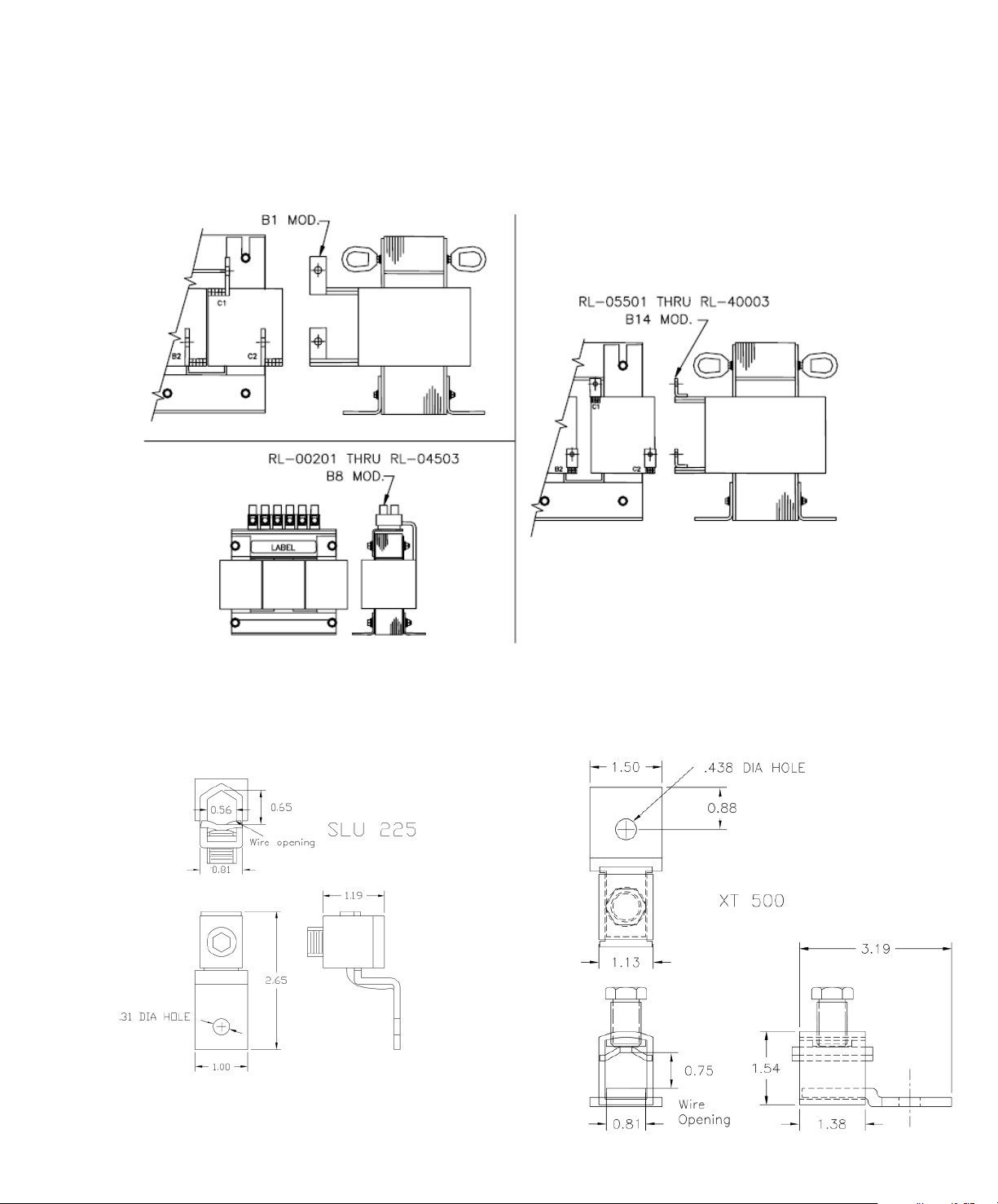
LUG OPTION DETAILS:
“B1” Terminal Modification “B14” Terminal Modification
“B8” Terminal Modification
Wire range: 2 - 0000
“SLU” Lug Option
Wire range: 00 – 500 mcm
Page 9
MTE AC Line / Load Reactors
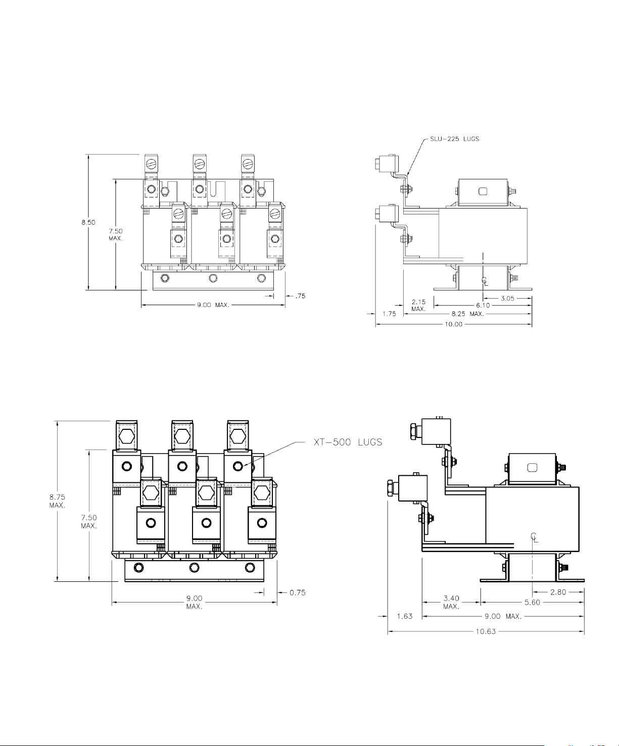
SLU Lug Options cont.
User Manual
SLU 225 shown on 200 amp Reactor
XT 500 shown on 250 amp Reactor
Page 10

MTE AC Line / Load Reactors
User Manual
PRODUCT SPECIFICATIONS
Standard impedance values 1-1/2%, 2, 3%, 4%, 5% available
Impedance basis Reactor fundamental current rating
Service Factor
(Continuous)
Reactors rated 1 to 750 Amps 150% of fundamental rating
Reactors rated above 750 Amps 125% of fundamental rating minimum
Note: Select reactor based on fundamental current
rating
Overload Rating 200% of fundamental for 30 minutes
300% of fundamental for 1 minute
Maximum system voltage 600 Volts ( units with terminal blocks)
690 Volts (units with box lugs or tab terminals)
Maximum switching frequency 20 KHz
Insulation system Class N (200° C)
Temperature rise
Open or enclosed reactors 135° C (average)
Ambient temperature
Open or enclosed reactors 45° C (maximum)
Altitude (maximum) 1000 meters
Fundamental frequency
Line or Load 50/60 Hz
Approvals: CE, UL-508, CSA C22.2
Inductance curve (typical) 100% at 100% current
100% at 150% current
50% at 350% current (minimum)
Inductance tolerance +/- 10%
Impregnation: High Bond Strength “Solvent less” Epoxy, 200° C
UL94HB recognized
Dielectric Strength 3000 volts rms (4243 volts peak)
dv/dt Protection Meets NEMA MG-1, part 31 (same as inverter duty
motors)
Protection: Open reactors with terminal blocks through 45 amps
meet IP20
Page 11

MTE AC Line / Load Reactors
User Manual
PRODUCT SPECIFICATIONS (cont’d)
AGENCY APPROVALS:
UL-508, File E180243 Component Listed (1 amp – 2400 amps)
UL-508, File E180243 UL Listed NEMA 1 units (1 amp – 2400 amps)
CSA C22.2, File LR29753-13 CSA Certified (1 amp – 2400 amps)
Class N, 200° C, File E66214, Type 200-18, UL Recognized Insulation System
CE Marked
MATERIAL:
Core Steel: Electrical grade silicon steel
Windings: High dielectric withstand solid copper conductor (220° C)
Enclosures: Sheet steel in accordance with UL and CSA requirements. Painted ANSI-61
Grey
Brackets: ASTM structural steel or structural aluminum
Terminations: 1 – 45 amps - Finger safe terminal block
55 - 160 amps - Solid copper box lugs (Tab terminals are optional)
200 + amps - Copper tab terminals
Sheet Insulation: DuPont Nomex 410 (220° C)
Epoxy: Ripley Resin Type 468-2 (220° C)
CONSTRUCTION:
CORE: Electrical grade silicon steel magnetic laminations.
WINDINGS: Meet 3000 volts rms dielectric strength (coil – to coil and coil- to – core).
ASSEMBLY: Windings are assembled onto EI laminations, secured in place and epoxy
impregnated for minimum noise and maximum structural rigidity.
COLOR: Royal Blue
TESTING: Electronic Turns Count (Zero Tolerance)
Inductance
Hi-Pot 3000 Volts rms (5656 volts peak)
Mechanical Inspection
Page 12

MTE AC Line / Load Reactors
User Manual
PRODUCT SPECIFICATIONS (cont’d)
AUDIBLE NOISE: Guard-AC Line/Load Reactors offer low noise operation. Core and coil
construction, flux density control, harmonic compensation as well as our epoxy impregnation process
assure minimal audible noise radiation. Although our reactors are typically “quiet”, waveforms vary by
drive type and application and therefore reactor audible noise may vary by application. Noise levels may
be affected by type of motor and motor conductor as well as motor conductor length.
Typical audible noise levels for units selected from our catalog by HP rating are:
2 thru 12 amps 55 dBA
18 thru 100 amps 65 dBA
130 thru 400 amps 70 dBA
500 thru 1200 amps 75 dBA
Service Factor: Guard-AC reactors are compensated for the additional currents and high
frequencies caused by the presence of harmonics. The reactor fundamental current rating indicates the
typical full load motor current and is also the basis of impedance rating. Standard reactors rated 1 amps
thru 750 amps offer a full 1.5 service factor rating which allows them to carry overload current up to 150%
of their fundamental rating when applied as an input line reactor. Since the nameplate ratings of motor
drives (ASD) varies widely by manufacturer, this helps to assure that the reactor maximum current rating
is compatible with the nameplate current rating on the ASD. The service factor rating compensates for
ASD manufacturer variances in motor drive current ratings and for harmonic currents. Nominal
inductance is assured all the way up to the service factor current rating.
PWM / IGBT PROTECTION: Guard-AC reactors are protected against the high peak voltage and fast
rise time voltage pulses associated with PWM waveforms. The dielectric strength is 4000 volts rms and
Guard-AC reactors meet the ratings of an inverter duty motor (NEMA MG-1, part 31). For convenience,
they can be located either at the motor or at the drive.
HARMONIC ATTENUATION: Our unique harmonic compensation assures maximum circuit inductance
in the presence of complex waveforms and can be relied upon to minimize input total harmonic current
distortion (THID). Additionally it offers superior absorption of transient voltage spikes. Our standard
reactors will typically reduce 6-pulse rectifier input current harmonics to the following levels at full load
operating conditions:
3% reactor alone 45% or less THID
5% reactor alone 35% or less THID
3% AC reactor + 3% DC link choke 33% or less THID
5% AC reactor + 3% DC link choke 28% or less THID
(DC link choke inductance is equivalent ac impedance).
Page 13

MTE AC Line / Load Reactors
Reactor Temperature De-Rating
User Manual
DE-RATING CURVES
Altitude Derating Curve
1.05
1.00
0.95
0.90
0.85
0.80
0.75
0.70
Current De-Rating Factor
0 3300 6600 9900 13200 16500
Altitude (Feet)
1.05
1.00
0.95
0.90
0.85
0.80
0.75
0.70
0.65
Current De-Rating Factor
0.60
40 45 50 55 60 65 70 75 80 85 90
AmbientTemperature Deg. C
Page 14

Dimensions A, B, C show overall spacing allowances
Use dimension D and E for mounting pattern
Page 15

MTE AC Line / Load Reactors
User Manual
Mounting Compatibility
Page 16

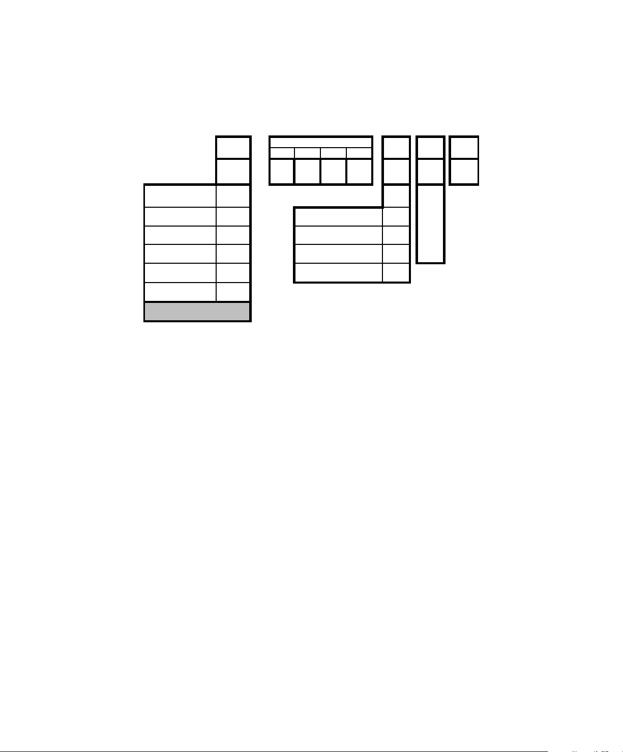
MTE AC Line / Load Reactors
Cat. No.
Inches
mm
Inches
mm
Inches
mm
Inches
mm
Inches
mm
Lbs
Kg
User Manual
Mechanical Details Open Reactors
MTE Weight Mass
RL-00101 3.8 97 3.5 89 1.2 30 2.40 61.0 1.44 36.6 4 1.8
RL-00102 3.8 97 3.5 89 1.2 30 1.98 50.3 1.44 36.6 4 1.8
RL-00103 3.8 97 3.5 89 1.2 30 1.98 50.3 1.44 36.6 3 1.4
RL-00104 3.8 97 3.5 89 1.2 30 1.98 50.3 1.44 36.6 3 1.4
RL-00201 4.4 112 4.1 104 2.8 71 1.98 50.3 1.44 36.6 4 1.8
RL-00202 4.4 112 4.1 104 2.8 71 1.98 50.3 1.44 36.6 4 1.8
RL-00203 4.4 112 4.1 104 2.8 71 1.98 50.3 1.44 36.6 4 1.8
RL-00204 4.4 112 4.1 104 2.5 64 1.73 43.9 1.44 36.6 3 1.4
RL-00401 4.4 112 4.1 104 2.8 71 1.98 50.3 1.44 36.6 4 1.8
RL-00402 4.4 112 4.1 104 2.8 71 1.98 50.3 1.44 36.6 4 1.8
RL-00403 4.4 112 4.1 104 3.4 86 2.35 59.7 1.44 36.6 5 2.3
RL-00404 4.4 112 4.1 104 3.4 86 2.60 66.0 1.44 36.6 6 2.7
RL-00801 6.0 152 4.8 122 3.0 76 2.10 53.3 2.00 50.8 7 3.2
RL-00802 6.0 152 4.8 122 3.0 76 2.10 53.3 2.00 50.8 8 3.6
RL-00803 6.0 152 4.8 122 3.4 86 2.62 66.5 2.00 50.8 11 5.0
RL-00804 6.0 152 4.8 122 3.4 86 2.48 63.0 2.00 50.8 13 5.9
RL-01201 6.0 152 5.0 127 3.3 84 2.10 53.3 2.00 50.8 9 4.1
RL-01202 6.0 152 5.0 127 3.3 84 2.10 53.3 2.00 50.8 10 4.5
RL-01203 6.0 152 5.0 127 3.9 99 2.75 69.9 2.00 50.8 18 8.2
RL-01801 6.0 152 5.3 135 3.2 81 2.10 53.3 2.00 50.8 9 4.1
RL-01802 6.0 152 5.3 135 3.5 89 2.48 63.0 2.00 50.8 12 5.4
RL-01803 8.1 206 6.1 155 4.0 102 2.60 66.0 3.00 76.2 16 7.3
RL-02501 7.2 183 5.8 147 3.5 89 2.35 59.7 3.00 76.2 11 5.0
RL-02502 7.2 183 5.8 147 3.5 89 2.35 59.7 3.00 76.2 14 6.3
RL-02503 7.2 183 5.8 147 4.3 109 3.10 78.7 3.00 76.2 20 9.1
RL-03501 7.2 183 5.8 147 4.0 102 2.60 66.0 3.00 76.2 14 6.3
RL-03502 7.2 183 5.8 147 4.0 102 2.75 69.9 3.00 76.2 16 7.3
RL-03503 9.0 229 7.4 188 4.7 119 3.16 80.3 3.00 76.2 30 14
RL-04501 9.0 229 7.4 188 4.7 119 3.16 80.3 3.00 76.2 23 10
RL-04502 9.0 229 7.4 188 4.7 119 3.16 80.3 3.00 76.2 28 13
RL-04503 9.0 229 7.3 185 5.3 135 3.66 93.0 3.00 76.2 39 18
RL-05501 9.0 229 7.3 185 5.3 135 3.16 80.3 3.00 76.2 24 11
RL-05502 9.0 229 7.0 178 5.3 135 3.16 80.3 3.00 76.2 27 12
RL-05503 9.0 229 7.0 178 6.0 152 3.91 99.3 3.00 76.2 41 19
RL-08001 9.0 229 7.2 183 6.3 160 3.47 88.1 3.63 92.2 25 11
RL-08002 9.0 229 7.2 183 6.5 165 3.47 88.1 3.63 92.2 33 15
RL-08003 10.8 274 8.5 216 6.8 173 4.16 105.7 3.63 92.2 61 28
RL-10001 9.0 229 7.3 185 6.5 165 3.30 83.8 3.63 92.2 29 13
RL-10002 9.0 229 7.3 185 6.8 173 3.66 93.0 3.63 92.2 37 17
RL-10003 10.8 274 8.3 210 6.2 156 4.16 105.7 3.63 92.2 74 34
RL-13001 9.0 229 7.0 178 4.7 118 3.16 80.3 3.00 76.2 29 13
RL-13002 9.0 229 7.2 183 6.8 173 3.66 93.0 3.63 92.2 43 20
RL-13003 11.0 279 8.5 216 6.2 156 4.16 105.7 3.63 92.2 64 29
RL-16001 9.0 229 7.2 183 6.8 173 3.16 80.3 3.63 92.2 41 19
RL-16002 10.8 274 8.3 211 6.0 152 3.47 88.1 3.63 92.2 50 23
EA B C D
Page 17

MTE AC Line / Load Reactors
Cat. No.
Inches
mm
Inches
mm
Inches
mm
Inches
mm
Inches
mm
Lbs
Kg
User Manual
Mechanical Data Open Type Cont.
MTE Weight Mass
RL-20001B14
RL-20002B14 9.0 229 7.5 191 8.3 211 4.41 112.0 3.63 92.2 54 24
RL-20003B14 10.8 274 8.3 211 10.0 254 5.91 150.1 3.63 92.2 100 45
RL-25001B14 9.0 229 7.5 191 9.0 229 4.19 106.4 3.63 92.2 47 21
RL-25002B14 10.8 274 8.5 216 9.0 229 5.16 131.1 4.60 116.8 80 36
RL-25003B14 14.4 366 11.2 284 10.3 262 5.82 147.8 4.60 116.8 125 57
RL-32001B14 10.8 274 9.0 229 8.3 211 5.16 131.1 4.60 116.8 80 36
RL-32002B14 10.8 274 9.0 229 10.0 254 5.88 149.4 4.60 116.8 102 46
RL-32003B14 14.4 366 11.3 286 10.5 267 7.13 181.1 4.60 116.8 160 73
RL-40001B14 10.8 274 10.0 254 10.0 254 5.16 131.1 4.60 116.8 84 38
RL-40002B14 15.0 381 11.3 286 11.5 292 6.76 171.7 4.60 116.8 118 54
RL-40003B14 14.4 366 11.3 286 12.5 318 7.26 184.4 4.60 116.8 149 68
9.0 229 7.5 191 7.3 185 4.16 105.7 3.63 92.2 38 17
EA B C D
RL-50001 10.8 274 9.0 229 10.5 267 5.50 139.7 4.60 116.8 93 42
RL-50002 14.4 366 11.5 292 11.5 292 6.76 171.7 4.60 116.8 118 54
RL-50003 14.4 366 11.5 292 13.3 338 9.76 247.9 4.60 116.8 210 95
RL-60001 14.4 366 11.5 292 10.0 254 5.26 133.6 4.60 116.8 120 54
RL-60002 14.4 366 11.3 286 12.0 305 8.00 203.2 4.60 116.8 175 79
RL-60003 14.4 366 11.3 286 15.0 381 9.26 235.2 4.60 116.8 270 122
RL-75001 14.4 366 11.5 292 11.0 279 6.63 168.4 7.20 182.9 140 63
RL-75002 14.4 366 11.5 292 12.5 318 8.01 203.5 7.20 182.9 190 86
RL-75003 14.4 366 14.5 368 14.0 356 9.26 235.2 7.20 182.9 265 120
RL-85001 20.3 514 16.8 425 13.0 330 7.60 193.0 7.20 182.9 285 129
RL-85002 22.0 559 16.8 425 13.0 330 8.00 203.2 7.20 182.9 370 168
RL-85003 22.5 572 16.8 427 18.0 457 9.00 228.6 7.20 182.9 452 205
RL-100001 21.6 549 16.8 425 11.0 279 7.26 184.4 7.20 182.9 320 145
RL-100002 20.3 514 16.8 425 13.0 330 8.50 215.9 7.20 182.9 408 185
RL-100003 20.3 514 16.8 425 15.0 381 10.76 273.3 7.20 182.9 589 267
RL-120001 22.5 572 17.0 432 13.0 330 11.00 279.4 7.20 182.9 425 193
RL-120002 21.5 546 17.0 432 20.0 508 10.76 273.3 7.20 182.9 440 200
RL-120003 16.8 427 17.0 432 18.5 470 11.00 279.4 7.20 182.9 560 254
RL-140001 22.0 559 17.0 432 22.0 559 11.00 279.4 7.20 182.9 500 227
RL-140002 19.0 483 17.0 432 19.0 483 11.00 279.4 7.20 182.9 525 238
RL-140003 22.0 559 17.0 432 22.0 559 11.00 279.4 7.20 182.9 850 385
RL-150001 22.0 559 17.0 432 22.0 559 11.00 279.4 7.20 182.9 635 288
RL-150002 16.9 429 17.0 432 16.0 406 11.00 279.4 7.20 182.9 675 306
RL-150003 22.0 559 17.0 432 22.0 559 11.00 279.4 7.20 182.9 900 408
RL-180001 22.0 559 17.0 432 22.0 559 11.00 279.4 7.20 182.9 700 317
RL-180002 22.0 559 17.0 432 22.0 559 10.38 263.7 7.20 182.9 860 390
RL-180003 22.0 559 17.0 432 22.0 559 11.00 279.4 7.20 182.9 1090 494
RL-210001 24.0 610 18.0 457 24.0 610 11.00 279.4 7.20 182.9 800 363
RL-210002 24.0 610 18.0 457 24.0 610 11.00 279.4 7.20 182.9 970 440
Page 18

MTE AC Line / Load Reactors
User Manual
Recommended conduit entry for Floor Mounted
NEMA 1 enclosed reactors
Note: The entry locations shown above are for reference only. The electrician installing the reactor
guided by the local codes determines the final entry wiring. MTE does not pre- punch entry holes or
provide wiring hardware with the standard product.
Page 19

MTE AC Line / Load Reactors
User Manual
ENCLOSURE DIMINSIONS
CAB-8
CAB-12C
Page 20

MTE AC Line / Load Reactors
User Manual
ENCLOSURE DIMENSIONS
CAB-13V
CAB-17V
Page 21

MTE AC Line / Load Reactors
User Manual
ENCLOSURE DIMENSIONS
CAB-17C
CAB-26C
Page 22

MTE AC Line / Load Reactors
User Manual
ENCLOSURE DIMENSIONS
CAB-30B
CAB-42C
Page 23

MTE AC Line / Load Reactors
Catalog
Watts Loss
Wire Range
Terminal Torque
Ind.
Fund
Max
Number
(watts)
(AWG)
(in–lbs)mHAmps
Amps
User Manual
TECHNICAL DATA
RL-00101 13.5 22 – 10 4.5 100 1 1.5
RL-00102 12.8 22 – 10 4.5 50 1 1.5
RL-00103 11.9 22 – 10 4.5 36 1 1.5
RL-00104 9.6 22 – 10 4.5 18 1 1.5
RL-00201 8 22 – 10 4.5 12 2 3
RL-00202 12 22 – 10 4.5 20 2 3
RL-00203 16 22 – 10 4.5 32 2 3
RL-00204 11 22 – 10 4.5 6 2 3
RL-00401 15 22 – 10 4.5 3 4 6
RL-00402 20 22 – 10 4.5 6.5 4 6
RL-00403 20 22 – 10 4.5 9 4 6
RL-00404 21 22 – 10 4.5 12 4 6
RL-00801 20 22 – 10 4.5 1.5 8 12
RL-00802 29 22 – 10 4.5 3 8 12
RL-00803 26 22 – 10 4.5 5 8 12
RL-00804 28 22 – 10 4.5 7.5 8 12
RL-01201 26 14 - 6 16 1.25 12 18
RL-01202 31 14 - 6 16 2.5 12 18
RL-01203 41 14 - 6 16 4.2 12 18
RL-01801 36 14 - 6 16 0.8 18 27
RL-01802 43 14 - 6 16 1.5 18 27
RL-01803 43 14 - 6 16 2.5 18 27
RL-02501 48 14 - 6 16 0.5 25 37.5
RL-02502 52 14 - 6 16 1.2 25 37.5
RL-02503 61 14 - 6 16 1.8 25 37.5
RL-03501 49 14 - 6 16 0.4 35 52.5
RL-03502 54 14 - 6 16 0.8 35 52.5
RL-03503 54 18 – 4 16 1.2 35 52.5
RL-04501 54 18 – 4 16 0.3 45 67.5
RL-04502 62 18 – 4 16 0.7 45 67.5
RL-04503 65 18 – 4 16 1.2 45 67.5
RL-05501 64 6 – 0 6-4(45) & 2-0(50) 0.25 55 82.5
RL-05502 67 6 – 0 6-4(45) & 2-0(50) 0.5 55 82.5
RL-05503 71 6 – 0 6-4(45) & 2-0(50) 0.85 55 82.5
RL-08001 82 6 – 0 6-4(45) & 2-0(50) 0.2 80 120
RL-08002 86 6 – 0 6-4(45) & 2-0(50) 0.4 80 120
RL-08003 96 6 – 0 6-4(45) & 2-0(50) 0.7 80 120
RL-10001 94 6 – 0 6-4(45) & 2-0(50) 0.15 100 150
RL-10002 84 6 – 0 6-4(45) & 2-0(50) 0.3 100 150
RL-10003 108 6 – 0 6-4(45) & 2-0(50) 0.45 100 150
RL-13001 108 2 – 0000 150 0.1 130 195
RL-13002 180 2 – 0000 150 0.2 130 195
RL-13003 128 2 – 0000 150 0.3 130 195
RL-16001 116 2 – 0000 150 0.075 160 240
Page 24

MTE AC Line / Load Reactors
Catalog
Watts Loss
Wire Range
Terminal Torque
Ind
Fund
Max
Number
(watts)
(AWG)
(in–lbs)mHAmps
Amps
User Manual
TECHNICAL DATA (cont’d)
RL-16002 149 Copper Tab Not Applicable 0.15 160 240
RL-16003 138 Copper Tab Not Applicable 0.23 160 240
RL-20001B14
RL-20002B14
RL-20003B14
RL-25001B14
RL-25002B14
RL-25003B14
RL-32001B14
RL-32002B14
RL-32003B14
RL-40001B14
RL-40002B14
RL-40003B14
RL-50001 266 Copper Tab Not Applicable 0.025 500 750
RL-50002 340 Copper Tab Not Applicable 0.05 500 750
RL-50003 422 Copper Tab Not Applicable 0.085 500 750
RL-60001 307 Copper Tab Not Applicable 0.02 600 900
RL-60002 414 Copper Tab Not Applicable 0.04 600 900
RL-60003 406 Copper Tab Not Applicable 0.065 600 900
RL-75001 427 Copper Tab Not Applicable 0.015 750 1125
RL-75002 630 Copper Tab Not Applicable 0.029 750 1125
RL-75003 552 Copper Tab Not Applicable 0.048 750 1125
RL-85001 798 Copper tab Not Applicable 0.015 850 1063
RL-85002 930 Copper tab Not Applicable 0.027 850 1063
RL-85003 1133 Copper tab Not Applicable 0.042 850 1063
RL-90001 860 Copper tab Not Applicable 0.013 900 1125
RL-90002 1020 Copper tab Not Applicable 0.025 900 1125
RL-90003 1365 Copper tab Not Applicable 0.04 900 1125
RL-100001 940 Copper tab Not Applicable 0.011 1000 1250
RL-100002 1090 Copper tab Not Applicable 0.022 1000 1250
RL-100003 1500 Copper tab Not Applicable 0.038 1000 1250
RL-120001 980 Copper tab Not Applicable 0.009 1200 1500
RL-120002 1130 Copper tab Not Applicable 0.019 1200 1500
RL-120002 1550 Copper tab Not Applicable 0.03 1200 1500
RL-140001 Copper tab Not Applicable 0.008 1400 1750
RL-140002 1523 Copper tab Not Applicable 0.016 1400 1750
RL-140003 1680 Copper tab Not Applicable 0.027 1400 1750
RL-150001 1432 Copper tab Not Applicable 0.008 1500 1875
RL-150002 1671 Copper tab Not Applicable 0.015 1500 1875
RL-150003 1815 Copper tab Not Applicable 0.025 1500 1875
124 Copper Tab Not Applicable 0.055 200 300
168 Copper Tab Not Applicable 0.11 200 300
146 Copper Tab Not Applicable 0.185 200 300
154 Copper Tab Not Applicable 0.045 250 375
231 Copper Tab Not Applicable 0.09 250 375
219 Copper Tab Not Applicable 0.15 250 375
224 Copper Tab Not Applicable 0.04 320 480
264 Copper Tab Not Applicable 0.075 320 480
351 Copper Tab Not Applicable 0.125 320 480
231 Copper Tab Not Applicable 0.03 400 600
333 Copper Tab Not Applicable 0.06 400 600
293 Copper Tab Not Applicable 0.105 400 600
Contact factory for higher ratings.
Page 25

MTE AC Line / Load Reactors
User Manual
INSTALLATION INSTRUCTIONS
Open Line/Load Reactor Installation
MTEline/loadreactors are availableinopen
construction and in NEMA 1 enclosures.
Open reactorsaredesignedformounting within
anappropriateelectrical equipment
enclosure. Reactorsrated300amperesRMS
andunderaredesignedfor mountingin both a
vertical and horizontalposition. Larger
reactors must be mountedina horizontal
positiontypicallyonthefloorof theenclosure.
Includethepowerdissipation of the reactor
along with all the other componentslocated in
theenclosuretodeterminetheinternal
temperature rise and cooling requirements
of the enclosure.
Reactorsmaybelocated inanyregion ofthe
enclosurewhere the ambienttemperature
does not exceed45degreesC.Allowaminimum
sideclearancesof four (4) inches andvertical
clearancesofsix(6)inchesforproperheat
dissipationand access. Do notlocate the
reactornexttoresistorsor anyothercomponent
withoperating surfacetemperatures above 125
degree C.
Select a wellventilated,dust-freearea awayfrom
directsunlight,rainormoisture.Donotinstallin or
neara corrosiveenvironment.Avoidlocations
where the reactor will be subjected to
excessive vibrations.
NEMA 1 Line/Load Reactor Installation
Top conduit entry recommended for
NEMA 1 enclosed reactors.
MTEline/loadreactors mountedinenclosures
withpart number, CAB-8, are designed for
wall mounting.Allother enclosuresare
designedforfloormounting.
WARNING
MTE NEMA1 enclosures designed for floor
mounting must be mounted with the
enclosure base horizontal for proper
ventilation. Wall mounting a floor
mounted enclosure with the base against
thewallwillcausethe reactor to over heat
resulting in equipment damage.
Allowaminimumside,front,andback
clearancesof twelve (12) inchesand vertical
clearancesofeighteen(18) inchesforproper
heatdissipationand access. Do notlocate the
enclosurenexttoresistors oranyother
componentwithoperatingsurfacetemperatures
above 125 degreeC.
Select a wellventilated,dust-freearea away
fromdirect sunlight,rainor moisture
where the ambienttemperaturedoesnot
exceed40degreesC.
Donotinstallinornearacorrosiveenvironment.
Avoidlocationswherethereactor willbe
subjectedtoexcessivevibrations.
Wheredesirable,enclosuresmaybemounted
onvibrationisolating pads to reduceaudible
noise.Standardvibrationcontrol padsmade
fromneoprene or natural rubber and
selected for the weight ofthe enclosedreactor
are effective. Usingflexible conduit is also
helpful in abatement of audible noise.
Page 26

MTE AC Line / Load Reactors
User Manual
Power Wiring Connection
WARNING
Input and output power wiring to the
reactor should be performed by
authorized personnel in accordance
with the NEC and all local electrical
codes and
REGULATIONS
WARNING
Failure to connect reactors supplied
as a component part of a drive
system or other power electronic
system according to the system
interconnection diagram supplied by
the System Engineer will result in
equipment damage, injury, or death.
Verify that the power source to which the reactor
is to be connected is in agreement with the
nameplate data on the reactor. A fused
disconnect switch or circuit breaker should be
installed between the reactor and its source of
power in accordance with the requirements of
the NEC and all local electrical codes and
regulations. Refer to the drive, inverter, or other
electrical equipment user manual for selection of
the correct fuse rating and class.
The reactor is suitable for use on a circuit
capable of delivering not more than 65,000 rms
symmetrical amperes at 480 volts when
protected by Bussman type JJS, KTK, KTK-R,
SPP or T class fuses.
Reactor are designed for use with copper
conductors with a minimum temperature rating
of 75 degrees C. Table 2 lists the wire range and
terminal torque requirements for the power input
and output connections by reactor part number.
Refer to Figure 4 for typical electrical diagrams
describing the application of reactors in both line
and load applications. For reactors supplied as a
component part of a drive system or a
component part of power electronic apparatus
follow the interconnection diagram supplied by
the System Engineer.
WARNING
If a line reactor or a line reactor and a load
reactor are used with a drive equipped with a
bypass circuit, the reactors must be removed
from the motor circuit in the bypass mode.
Damage to the motor and other equipment will
result if this warning is not observed.
Grounding
A stud is provided on enclosed reactors for
grounding the enclosure. The enclosure must be
grounded. Open reactors must be grounded at
the designated grounding terminal or the reactor
mounting holes if no designated grounding
terminal is provided.
WARNING
The frame of line/load reactors must be
grounded at the designated grounding terminal
or one of the reactor mounting holes if no
designated grounding terminal is provided. The
enclosure of reactors supplied in enclosures
must be grounded.
INJURY OR DEATH MAY RESULT IF
SAFETY PRECAUTIONS ARE NOT
OBSERVED.
Where desirable, a flexible conduit connection to
the reactor enclosure should be made to reduce
audible noise.
Page 27

MTE AC Line / Load Reactors
User Manual
Typical Connection Diagrams
Fig 4a LINE Reactor
Connects between power source and VFD
Fig. 4b LOADReactor
Connects between ASD and load (motor)
Figure 5.Single Phase connection diagram.
Fig 4c Use individual Line Reactors for
independent start/ stop drives connected to a
common power source. If inverters are slaved
and will always run together a single reactor
sized for total motor current may be used.
Page 28

MTE AC Line / Load Reactors
User Manual
Sequence of Operation
1. Read and follow safety precautions.
2. After installation, ensure that:
All Reactorgroundterminals are connectedtoground.
Power wiring to the utility, drive and motor is in accordance with the
interconnection diagrams supplied by the System Engineer.
3. Check that moisture has not condensed on the Reactor. If moisture is
present, do not proceedwithstartupuntilthe moisture hasbeen removed.
4. Proceed with startup according to the instructions provided by the system
supplier.
WARNING
Reactors areacomponentpartofanelectrical system.Do not proceed with startup until
the system startup instructions provided by the System Engineer are understood and
followed. Injury, death and damage to equipment may result if the system startup
instructions are not followed.
WARNING
Use extreme caution toavoidcontactwith linevoltagewhen checking for
power.
INJURY OR DEATH MAY RESULT IF SAFETY PRECAUTIONS ARE
NOT OBSERVED.
Page 29

MTE AC Line / Load Reactors
User Manual
STARTUP
Safety Precautions
Before startup, observe the following warnings and instructions:
WARNING
AReactor isat linepotentialwhentheReactoris connected to the utility. This voltage
is extremelydangerousand maycausedeathorsevere injury if you come in contact
with it.
WARNING
High voltage is used in the operation of line/load reactors. Use Extreme caution to
avoid contact with high voltage when operating, installing or repairing equipment
containing line/load reactors. Line/load reactors are used in conjunction with
inverters, or other electrical equipment that may feedback lethal voltages.
Follow the safety instructions in the equipment used with the reactor in addition
to the safety instruction in this manual.
INJURY OR DEATH MAY RESULT IF SAFETYPRECAUTIONS ARE NOT
OBSERVED.
 Loading...