

Page 1
M T E C o r p o r a t i o n
MATRIX FILTER
SERIES A
480 Volts 60 Hz
USER MANUAL
PART NO. INSTR - 002
REL. 060607
© 2000 MTE Corporation
PDF created with pdfFactory trial version www.pdffactory.com
Page 2

PDF created with pdfFactory trial version www.pdffactory.com
Page 3

IMPORTANT USER INFORMATION
NOTICE
The MTE Corporation Matrix Filter is designed for harmonic mitigation of six
pulse inverter drives supplying variable torque loads in a wide variety of
applications. The suitability of this filter for a specific application must
therefore be determined by the customer. In no event will MTE Corporation
assume responsibility or liability for any direct or consequential damages
resulting from the use or application of this filter. Nor will MTE Corporation
assume patent liability with respect to the use of information, circuits or
equipment described in this instruction manual.
PDF created with pdfFactory trial version www.pdffactory.com
Page 4

PDF created with pdfFactory trial version www.pdffactory.com
Page 5

TABLE OF CONTENTS
1. Safety .......................................................................................................... 1
2. Introduction ................................................................................................. 3
3. Model Number Codes.................................................................................. 4
4. Specifications .............................................................................................. 5
Ratings ....................................................................................................... 5
Service Conditions ..................................................................................... 5
Performance ............................................................................................... 6
Altitude Derating Curve ............................................................................ 10
5. Installation Instructions ............................................................................. 11
Filter Installation ....................................................................................... 11
Power Wiring Connection ......................................................................... 11
Ground and Ground Fault Protection......................................................... 12
Input and Output Terminal Specifications ................................................. 12
Outline Drawings and Mounting Dimensions ............................................ 13
Interconnection Diagrams.......................................................................... 23
6. Filter Description ....................................................................................... 26
7. Start – Up .................................................................................................. 28
8. Troubleshooting......................................................................................... 29
8. Addendum A.............................................................................................. 33
PDF created with pdfFactory trial version www.pdffactory.com
Page 6

1. IMPORTANT SAFETY INFORMATION
WARNING
ONLY A QUALIFIED ELECTRICIAN CAN CARRY OUT THE ELECTRICAL
INSTALLATION OF THIS FILTER
WARNING
High voltage is used in the operation of this filter. Use Extreme caution to avoid
contact with high voltage when operating, installing or repairing this filter. INJURY
OR DEATH MAY RESULT IF SAFETY PRECAUTIONS ARE NOT OBSERVED.
After removing power, allow at least five minutes to elapse and verify that the
capacitors have discharged to a safe level before contacting internal components.
Connect a DC voltmeter across the capacitor terminals 1, 2 and 3 on terminal block
1TB. Start with the meter on the highest scale and progressively switch to a lower
scale as the indicated voltage falls below the maximum value of the scale used.
WARNING
The opening of the branch circuit protective device may be an indication that a fault current
has been interrupted. To reduce the risk of fire or electrical shock, current-carrying parts and
other components of the filter should be examined and replaced if damaged.
WARNING
An upstream disconnect/protection device must be used as required by the National
Electrical Code (NEC).
WARNING
Even if the upstream disconnect/protection device is open, the drive down stream of the filter
may feed back high voltage to the filter. The drive safety instructions must be followed.
INJURY OR DEATH MAY RESULT IF THE DRIVE SAFETY PRECAUTIONS ARE
NOT OBSERVED.
PDF created with pdfFactory trial version www.pdffactory.com
1
Page 7

WARNING
The filter must be grounded with a grounding conductor connected to all grounding terminals.
WARNING
Only spare parts obtained from MTE Corporation or an authorized MTE distributor can be
used.
2
PDF created with pdfFactory trial version www.pdffactory.com
Page 8

2. INTRODUCTION
This manual was specifically developed to
assist in the installation, interconnection
and operation of the MTE Corporation
Matrix Filter.
This manual is intended for use by
personnel experienced in the operation and
maintenance of electronic drives. Because
of the high voltages required by the filter
and drive and the potential dangers
presented by rotating machinery, it is
essential that all personnel involved in the
operation and maintenance of this filter
know and practice the necessary safety
precautions for this type of equipment.
Personnel should read and understand the
instructions contained in this manual before
installing, operating or servicing the filter
and the drive to which the filter is
connected.
Upon Receipt of this Filter:
The MTE Matrix Filter has been subjected
to demanding factory tests before shipment.
Carefully inspect the shipping container for
damage that may have
occurred in transit. Then unpack the filter
and carefully inspect for any signs of
damage. Save the shipping container for
future transport of the filter.
In the event of damage, please contact
and file a claim with the freight carrier
involved immediately.
If the equipment is not going to be put into
service upon receipt, cover and store the
filter in a clean, dry location. After storage,
ensure that the equipment is dry and that
no condensation has accumulated on the
internal components of the filter before
applying power.
Repair/Exchange Procedure
MTE Corporation requires a Returned
Material Authorization Number before it can
accept any filters that qualify for return or
repair. If problems or questions arise during
installation, setup, or operation of the filter,
please call us for assistance at:
Phone: 262-253-8200
FAX: 262-253-8222
PDF created with pdfFactory trial version www.pdffactory.com
3
Page 9
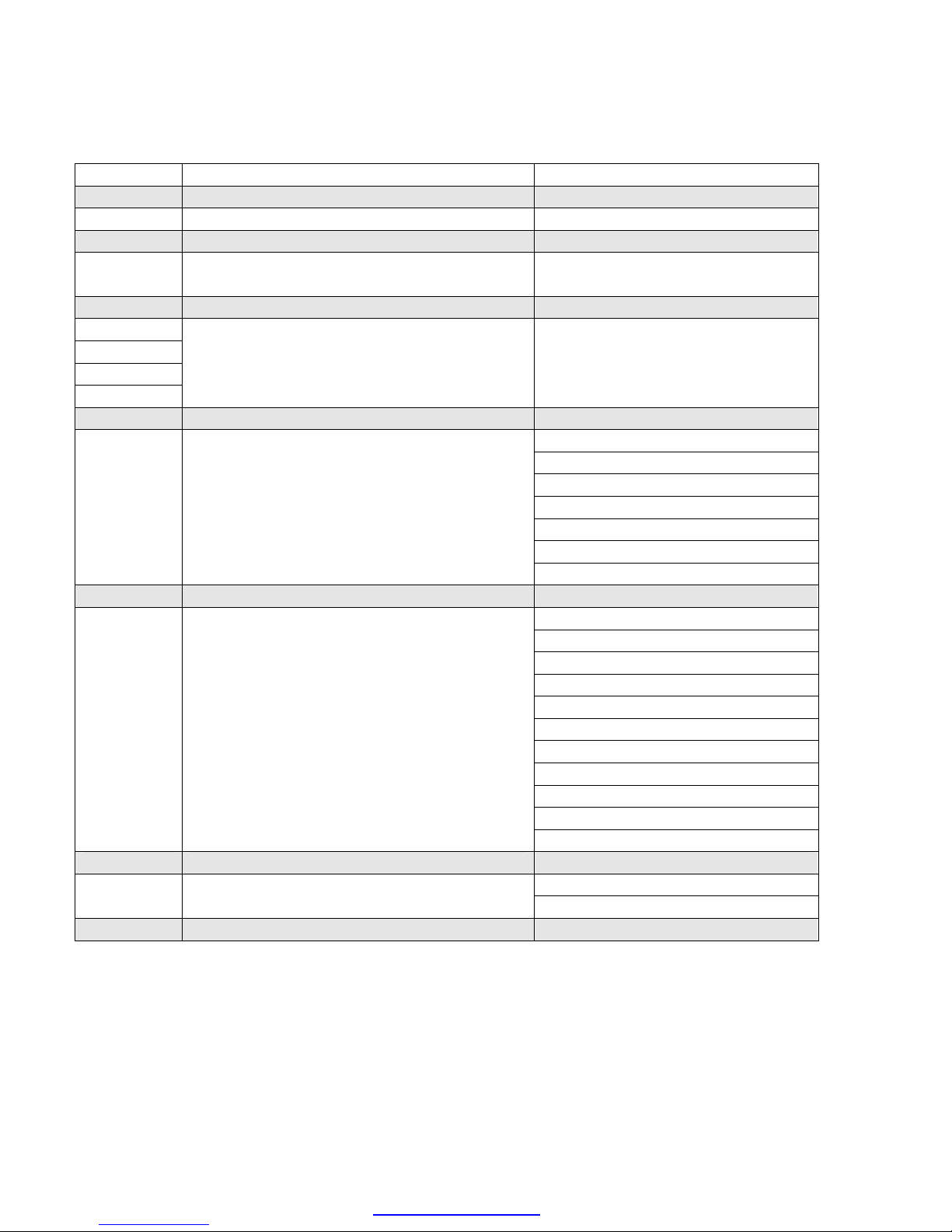
3. MODEL NUMBER CODES
Standard series A model number codes are of the form MA-BCDEFG-XY with the
number coded as outlined below.
Character
M Always M for Matrix Filter
A Designates number of input phases 1 Single phase
3 Three phase
B Characters B through E designate the Example: 0075 is a 75 Hp filter
C Horsepower rating of the filter using
D four digits with leading zeros
E
F Indicates mechanical configuration N Nema1
R Reactive components only
M Magnetic components only
P Panel mounted
W Weather proof
D Dust tight
H Hose down
G Designates input voltage and frequency A 208-240 v / 60Hz
B 240 v / 50 Hz
C 380-415 v / 50 Hz
D 480 v / 60 Hz
E 600 v / 60 Hz
F 690 v / 50 Hz
G 690 v / 60 Hz
H 120 v / 60 Hz
J
K
L 277 v / 60Hz
XY Designates filter guaranteed harmonic 12 is 12% THID
current performance 8 is 8% THID
Description Code
4
PDF created with pdfFactory trial version www.pdffactory.com
Page 10
4. SPECIFICATIONS
Maximum
Dissipation
Dissipation
Ratings
THID Rating 12% 8%
480 VAC Three Phase Input Filter Ratings
(Panel Mounted)*
Power
Maximum
HP
3 6 6 97 47 27 98 40 37
5 9 10 98 66 35 98 63 42
7.5 13 14 98 98 35 98 98 42
10 16 18 98 114 45 98 108 60
15 24 27 98 166 50 98 170 75
20 31 34 98 204 85 98 212 100
25 39 43 98 275 85 98 257 100
30 46 51 98 295 105 98 323 130
40 60 66 98 390 125 98 374 155
50 75 82 98 475 150 98 506 190
60 89 97 98 586 150 98 584 190
75 110 121 98 659 200 98 655 250
100 143 157 98 837 215 98 838 280
125 179 197 98 971 250 98 1051 305
150 207 228 99 1018 275 99 1057 340
200 276 304 98 1521 380 98 1775 600
250 347 382 99 1767 450 98 1889 675
300 415 457 99 1994 575 99 2099 750
Input
Amps
RMS
Output
Amps
RMS
Efficiency
(Typical)
(%)
@ Rated
HP
(Typical)
(Watts)
Weight
(lbs)
Efficiency
(Typical)
(%)
Power
@ Rated HP
(Typical)
(Watts)
Weight
(lbs)
*Refer to Addendum A for Enclosed Current Ratings
Service Conditions
Load: 6 pulse variable torque rectifier only
Input voltage: 480 VAC +/- 10%, 60 + 0.75 Hz, 3 phase
Input voltage line unbalance: 1% maximum
Maximum source impedance: 6.00%
Minimum source impedance: 1.5%
Service Factor: 1.00
PDF created with pdfFactory trial version www.pdffactory.com
5
Page 11

SPECIFICATIONS – continued
Ambient Temperature
Operating: -40 to +50 degrees C (panel mounted construction)
Storage: -40 to +90 degrees C
Altitude: 0 to 3300 Feet above sea level. Refer to Figure 1 for altitude derating.
Relative Humidity: 0 to 95% non-condensing
Agency Approvals
UL-508 File E180243 Component Recognized
(3-1000 HP, 120 VAC through 600 VAC
50, 50/60, 60 HZ Three Phases
CAN/CSA C22, 2 No. 14-95
Performance
Total Harmonic Current Distortion:
Standard: 12% maximum no load to full load
Optional: 8% maximum no load to full load
Standby Current:
Without Optional Capacitor Contactor: Refer to Table 1
With Optional Capacitor Contactor: Refer to Drive Users Manual
12% Filter Voltage Regulation with nominal 480 volts RMS source
Maximum output voltage at no load: 502 volts RMS, 710 volts peak
Maximum PCC* voltage with 6.00% source impedance at no load: 490 volts RMS, 693 volts peak
Minimum output voltage at full load: 460 volts RMS, 600 volts peak
8% Filter Voltage Regulation with nominal 480 volts RMS source
Maximum output voltage at no load: 502 volts RMS, 710 volts peak
Maximum PCC voltage with 6.00% source impedance at no load: 490 volts RMS, 693 volts peak
Minimum output voltage at full load: 460 volts RMS, 600 volts peak
*Note: PCC is the point of common coupling with the power distribution system
6
PDF created with pdfFactory trial version www.pdffactory.com
Page 12
SPECIFICATIONS - continued
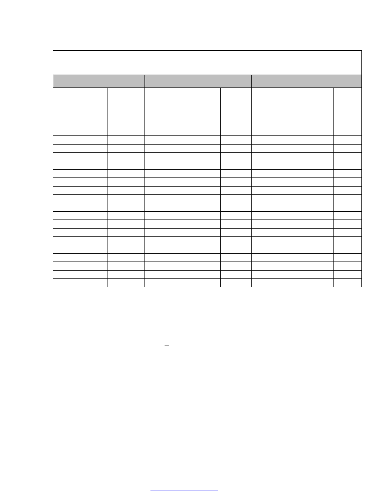
Table 1. 480 VAC Three Phase Input Filters
Standby Current Ratings Without Optional Capacitor Contactor
Standby
Current
HP
(Typical)
Amps
RMS
3 1.7 25 11.0 100 41.0
5 2.3 30 16.0 125 64.0
7-1/2 4.0 40 16.0 150 81.0
10 4.5 50 23.0 200 101.0
15 7.9 60 23.0 250 121.0
20 11.0 75 27.0 300 148.0
HP Standby
Current
(Typical)
HP
Amps
RMS
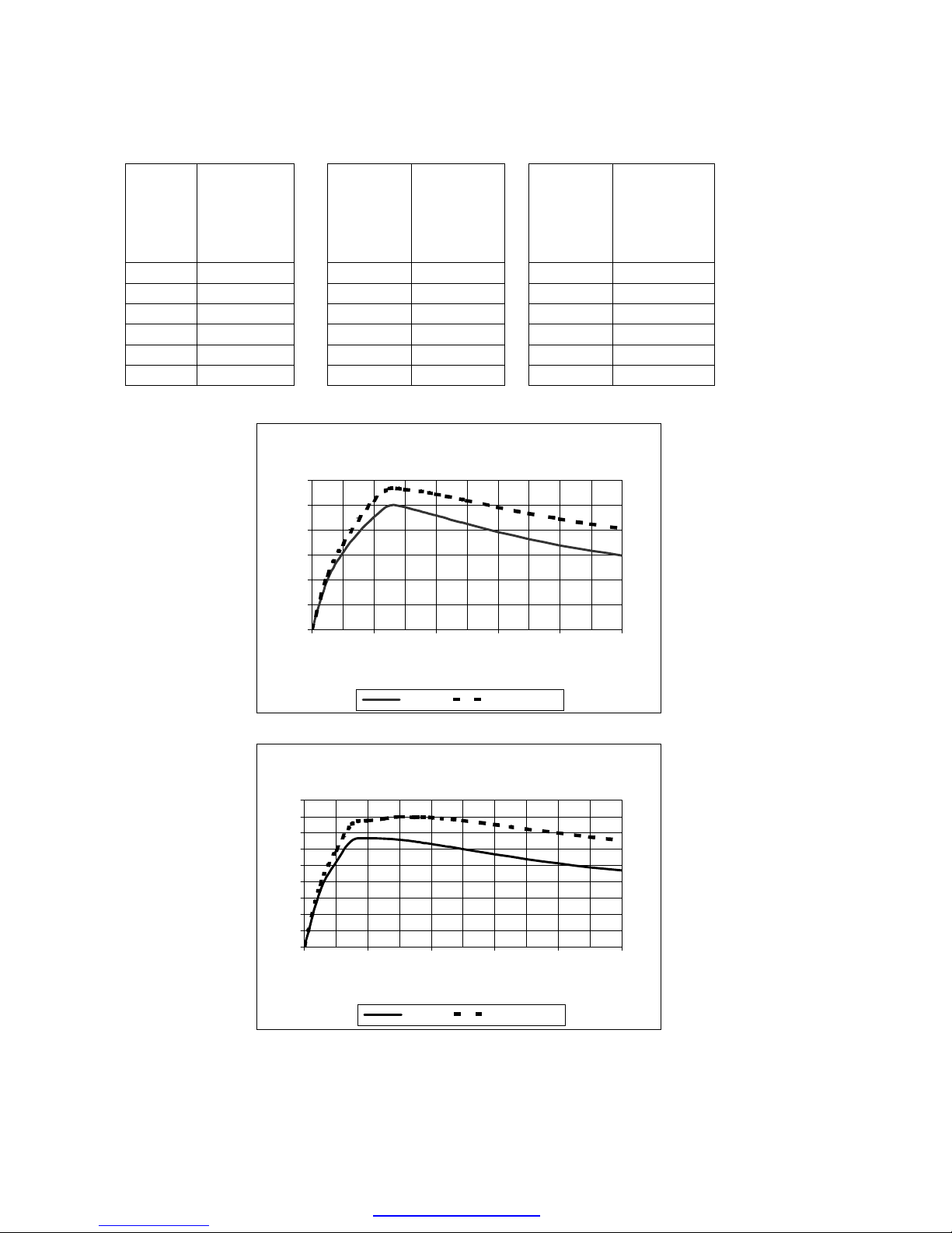
12% Filter THD vs Load
12
10
8
6
4
Percent THD
2
0
0 20 40 60 80 100
Percent Load
Standby
Current
(Typical)
Amps
RMS
Typical Worst Case
8% Filter THD vs Load
9
8
7
6
5
4
3
Percent THD
2
1
0
0 20 40 60 80 100
Percent Load
Typical Worst Case
7
PDF created with pdfFactory trial version www.pdffactory.com
Page 13

SPECIFICATIONS – continued
12% Filter Harmonic Spectrum
100% Load
7%
6%
5%
4%
3%
2%
1%
Harmonic Curent
0%
180
300
420
540
Frequency - Hz
Typical Worst Case
660
780
900
1020
1140
8% Filter Harmonic Spectrum
100% Load
6%
5%
4%
3%
2%
1%
Harmonic Current
0%
180
300
420
540
Frequency - Hz
660
780
900
1020
1140
Typical Worst Case
8
PDF created with pdfFactory trial version www.pdffactory.com
Page 14

SPECIFICATIONS - continued
12% and 8% Filter Power Factor vs Load
Leading PF For All Loads
1.2
1
0.8
0.6
PF
0.4
0.2
0
0 20 40 60 80 100
Percent Filter Load
Typical Worse Case
Performance With Unbalanced Line Voltage (Typical)
All Components at Nominal Values
and Worse Case Service Conditions
Nominal THID
1% Unbalance
2% Unbalance
3% Unbalance
12% Filter 30% Load 8% Filter 30% Load
Nominal THID
1% Unbalance
2% Unbalance
3% Unbalance
12% Filter 100% Load 8% Filter 100% Load
5.85% 4.71%
6.09% 4.92%
6.64% 5.46%
7.45% 6.29%
9.38% 6.42%
9.79% 6.90%
10.97% 8.13%
12.66% 9.80%
PDF created with pdfFactory trial version www.pdffactory.com
9
Page 15

1.05
Figure 1. Altitude Derating Curve
1.00
0.95
0.90
0.85
0.80
0.75
0.70
CURRENT DERATING FACTOR
0 3300 6600 9900 13200 16500
ALTITUDE (FEET)
10
PDF created with pdfFactory trial version www.pdffactory.com
Page 16

5. INSTALLATION
INSTRUCTIONS
Filter Installation
Panel mounted filters are designed for
mounting in the vertical plane in the
customer’s enclosure. Include the power
dissipation of the filter along with all the
other components located in the panel to
determine the internal temperature rise and
cooling requirements of the enclosure.
Select a well ventilated, dust-free area away
from direct sunlight, rain or moisture.
Do not install in or near a corrosive
environment.
Avoid locations where the filter would be
subjected to excessive vibrations.
The Matrix Filters are supplied as sub-panel
and panel mountable components that are
designed to be mounted in a vertical
position on a main panel located within an
appropriate electrical enclosure. Allow
minimum side clearances of four (4) inches
and vertical clearances of six (6) inches for
proper heat dissipation and access. Figures
2 though 11 contain outline drawings for the
various ratings and show proper mounting
orientation.
Power Wiring Connection
WARNING
Input and output power wiring to the
filter should be performed by
authorized personnel in accordance
with the NEC and all local electrical
codes and regulations.
Verify that the power source to which the
filter is to be connected is in agreement with
the nameplate data on the filter. A fused
disconnect switch or circuit breaker should
be installed between the filter and its source
of power in accordance with the
requirements of the NEC and all local
electrical codes and regulations. Refer to
the drive user manual for selection of the
correct fuse rating and class.
The filter is suitable for use on a circuit
capable of delivering not more than 100,000
rms symmetrical amperes at 480 volts when
protected by Bussman type JJS, KTK, KTKR, SPP or T class fuses.
For 480VAC applications rated 15 Hp and
below, interconnection between the filter, its
power source, and the drive is shown in
Figure 12. Refer to the drive user manual
for instructions on interconnecting the drive
and motor and the correct start-up
procedures for the drive.
The filter is designed for use with copper
conductors with a minimum temperature
rating of 75 degrees C. Table 2 lists the wire
range and terminal torque requirements for
the power input and output connections by
horsepower rating.
For 480 VAC filters rated 20 Hp or more, the
filter reactors are supplied on a sub-panel
and the filter capacitors are supplied on one
or more assembles. Refer to Figure 13 for
the interconnection diagram. The capacitor
assembly should be located in the lowest
temperature regions of the enclosure –
generally toward the bottom – and the
reactor assembly may be located in any
region where the ambient temperature
does not exceed 50 degrees C. Size the
conductors interconnecting the reactor and
capacitor assemblies to carry the current
shown in Table 3. For terminal
specifications on the capacitor assembly,
refer to Table 4.
PDF created with pdfFactory trial version www.pdffactory.com
11
Page 17

INSTALLATION
INSTRUCTIONS – continued
Grounding and Ground Fault
Protection
Table 2. Input and Output Terminal Specifications
Filter
Rating(HP)
3 22 -14 4.5 22 – 14 4.5
5 22 - 14 4.5 22 – 14 4.5
7.5 22 - 14 4.5 22 – 5 16
10 22 - 5 16 22 – 5 16
15 22 - 5 16 22 – 5 16
20 22 - 5 16 18 – 4 20
25 22 - 5 16 18 – 4 20
30 18 – 4 20 18 – 4 20
40 18 – 4 20
Wire Range
(AWG)
Input Terminals Output Terminals
The filter must always be grounded with a
grounding conductor connected to all ground
terminals.
Due to high leakage currents associated with
variable frequency drives, ground fault
protective devices do not necessarily operate
correctly when placed ahead of a matrix filter
feeding a drive. When using this type of
device, its function should be tested in the
actual installation.
Terminal Torque
(in-lbs)
Wire Range
(AWG)
6-4
2-0
Terminal Torque
(in-lbs)
45
50
50
60
75
100
125 2 – 0000 150 2 – 0000 150
150 2 – 0000 150 2 – 0000 150
200 2-0000 150
250
300
6-4
2-0
6-4
2-0
6-4
2-0
6-4
2-0
00
000-0000
250-350 MCM
500 MCM
00
000-0000
250-350 MCM
500 MCM
45
50
45
50
45
50
45
50
180
250
325
375
180
250
325
375
6-4
2-0
6-4
2-0
6-4
2-0
2-0000 150
00
000-0000
250-350 MCM
500 MCM
00
000-0000
250-350 MCM
500 MCM
00
000-0000
250-350 MCM
500 MCM
45
50
45
50
45
50
180
250
325
375
180
250
325
375
180
250
325
375
12
PDF created with pdfFactory trial version www.pdffactory.com
Page 18

INSTALLATION INSTRUCTIONS – continued
Figure 2. 3 – 10 HP, 480 VAC Outline Drawing
All dimensions are in inches
33
PDF created with pdfFactory trial version www.pdffactory.com
Page 19

INSTALLATION INSTRUCTIONS – continued
Figure 3. 15 HP, 480 VAC Outline Drawing
All dimensions are in inches
PDF created with pdfFactory trial version www.pdffactory.com
33
Page 20

INSTALLATION INSTRUCTIONS – continued
Figure 4. 20 - 40 HP, 480 VAC Outline Drawing
All dimensions are in inches
REACTOR ASSEMBLY
CAPACITOR ASSEMBLY
NOTE: CAPACITOR ASSEMBLY MAY BE MOUNTED IN EITHER PLANE
PDF created with pdfFactory trial version www.pdffactory.com
33
Page 21

INSTALLATION INSTRUCTIONS – continued
Figure 5. 50 - 60 HP, 480 VAC Outline Drawing
All dimensions are in inches
REACTOR ASSEMBLY
CAPACITOR ASSEMBLY
NOTE: CAPACITOR ASSEMBLY MAY BE MOUNTED IN EITHER PLANE
PDF created with pdfFactory trial version www.pdffactory.com
33
Page 22

INSTALLATION INSTRUCTIONS – continued
Figure 6. 75 HP, 480 VAC Outline Drawing
All dimensions are in inches
REACTOR ASSEMBLY
CAPACITOR ASSEMBLY
NOTE: CAPACITOR ASSEMBLY MAY BE MOUNTED IN EITHER PLANE
PDF created with pdfFactory trial version www.pdffactory.com
33
Page 23

INSTALLATION INSTRUCTIONS – continued
Figure 7. 100 HP, 480 VAC Reactor Assembly Outline Drawing
All dimensions are in inches
REACTOR ASSEMBLY
PDF created with pdfFactory trial version www.pdffactory.com
33
Page 24

INSTALLATION INSTRUCTIONS – continued
Figure 8. 100 HP, 480 VAC Capacitor Assembly Outline Drawing
All dimensions are in inches
NOTE: TWO CAPACITOR ASSEMBLIES REQUIRED
PDF created with pdfFactory trial version www.pdffactory.com
33
Page 25

INSTALLATION INSTRUCTIONS – continued
CAPACITOR
Figure 9. 125 - 150 HP, 480 VAC Outline Drawing
All dimensions are in inches
REACTOR ASSEMBLY
NOTE: SEE TABLE FOR NUMBER OF CAPACITOR ASSEMBLIES
NO. OF
HP
125 2
150 3
PANELS
NOTE: CAPACITOR ASSEMBLY MAY BE MOUNTED IN EITHER PLANE
PDF created with pdfFactory trial version www.pdffactory.com
33
Page 26

INSTALLATION INSTRUCTIONS – continued
Figure 10. 200 - 300 HP, 480 VAC Vertical Mounting Outline Drawing
All dimensions are in inches
PDF created with pdfFactory trial version www.pdffactory.com
33
Page 27

INSTALLATION INSTRUCTIONS – continued
Figure 11. 200 - 300 HP, 480 VAC Horizontal Mounting Outline Drawing
All dimensions are in inches
480 VAC Matrix Filters rated 200 HP through 300 HP, are constructed from a reactor assembly
and a capacitor assembly. These assemblies are designed to be mounted vertically. The reactor
assembly may be mounted above the capacitor assembly as shown in Figure 10 or the
assemblies may be mounted separately as shown in Figure 11. The capacitor assembly should
be located in the lowest temperature regions of the enclosure – generally toward the bottom.
The reactor and capacitor assemblies are shipped vertically oriented bolted and banded front-toback to a common pallet.
PDF created with pdfFactory trial version www.pdffactory.com
33
Page 28

INSTALLATION INSTRUCTIONS – continued
Figure 12. 3 – 15 HP Interconnection Diagram
PDF created with pdfFactory trial version www.pdffactory.com
33
Page 29

INSTALLATION INSTRUCTIONS – continued
Figure 13. 20 – 300 HP Interconnection Diagram
PDF created with pdfFactory trial version www.pdffactory.com
33
Page 30

INSTALLATION INSTRUCTIONS – continued
Table 3. Capacitor Assembly Current Ratings
HP
20 13 100 50
25 13 125 79
30 20 150 100
40 20 200 124
50 28 250 149
60 28 300 182
75 34
Current Rating
(Amps RMS)
Table 4. Capacitor Assembly Terminal Specifications
Filter Rating (HP)
HP
Capacitor Terminals
NOTE: Two terminals per phase
Current Rating
(Amps RMS)
20 – 150 HP
200 – 300 HP
Wire Range (AWG) Terminal Torque (in lbs)
14 – 10
8
4 – 6
1/0 – 3
6-00
35
40
45
50
120
PDF created with pdfFactory trial version www.pdffactory.com
33
Page 31

6. FILTER DESCRIPTION
The MTE Matrix Filter is a low pass filter
containing proprietary technology which makes
it particularly useful for harmonic mitigation of
adjustable speed drives. Figure 14 shows a
block diagram of the filter. Three phase AC
power is connected to the input section which
contains a three phase AC reactor and circuitry
which inhibits oscillation of the filter with the AC
power system. The center leg consists of a
series reactor and capacitor bank. Because of
the capacitor bank the filter operates with
leading power factor at all loads, but unlike trap
filters the MTE Matrix Filter does not produce
significant voltage rise at the point of common
coupling with the power system. The standard
12% filter output section consists of an AC
output reactor.
The 8% filter is comprised of a standard 12%
filter plus an additional output reactor.
Matrix filters are horsepower and current
rated. Current ratings have been
established on the basis of 115% of the
NEC 480 VAC motor ratings. Because the
filter operates at near unity power factor, a
motor drive system fed by a Matrix Filter
and operating at rated horsepower will draw
significantly less current than the filters
rated input current. For a drive system with
a typical efficiency of .85 and a Matrix Filter
with an efficiency of .98, the power into the
filter is (1/.98)(1/.85)(746)(HP) where HP is
the motor horsepower rating. The filter input
power is also equal to (√3)(Line
Current)(Line to Line Voltage). Equating
these two quantities and then calculating
the line current as a percent of rated filter
current for 10 HP, 100HP, and 300HP for
480 VAC results in the following data.
HP Rated Filter Current
%
10 67
100 75
300 78
Filter enclosures have been designed to
accommodate filter power dissipation at
rated horsepower. Filters mounted on open
panels are designed to carry rated current.
Select a matrix filter to match the horsepower
rating of the drive. For multiple drive
applications, the horsepower rating of the filter
should be equal to the total horsepower ratings
of the drives. For example, select a 100 Hp filter
to feed three 30Hp and one 10 Hp drives.
Multiple drives fed from a single filter may be
operated independently.
Because the filter supplies harmonic currents
required by the drive, linear loads (such as
space heaters, incandescent lighting and AC
motors operated across the line) should not be
connected to the output of the filter.
PDF created with pdfFactory trial version www.pdffactory.com
33
Page 32

Figure 14. Block Diagram
PDF created with pdfFactory trial version www.pdffactory.com
33
Page 33

7. STARTUP
Safety Precautions
Before startup, observe the following
warnings and instructions:
WARNING
Internal components of the filter are at
line potential when the filter is
connected to the utility. This voltage is
extremely dangerous and may cause
death or severe injury if you come in
contact with it.
WARNING
After disconnecting the utility power,
wait at least 5 minutes before doing any
work on the filter connections. After
removing power, allow at least five
minutes to elapse and verify that the
capacitors have discharged to a safe
level before contacting internal
components. Connect a DC voltmeter
across the capacitor terminals 1, 2 and
3 on terminal block 1TB. Start with the
meter on the highest scale and
progressively switch to a lower scale
as the indicated voltage falls below the
maximum value of the scale used.
Sequence of Operation
1. Read and follow safety precautions.
2. After installation, ensure that:
• All filter ground terminals are
connected to ground.
• Power wiring to the utility, drive
and motor is in accordance with
the installation and connection
instructions in Chapter 5.
3. Check that moisture has not
condensed on the filter components. If
moisture is present, do not proceed
with startup until the moisture has
been removed.
4. Disconnect the filter output from the
drive.
5. Connect the filter to the utility.
WARNING
Use extreme caution to avoid contact
with line voltage when checking for
power. INJURY OR DEATH MAY
RESULT IF SAFETY PRECAUTIONS
ARE NOT OBSERVED.
6. Confirm that line voltage is present at
the input terminals (A1, B1, C1) of the
filter.
7. Confirm that line voltage is present at
the output terminals (A2, B2, C2) of the
filter.
8. Disconnect the filter from the utility.
9. Connect the filter output to the drive.
10. Refer to the drive user manual for the
drive startup procedure. Observe all
safety instructions in the drive user
manual.
WARNING
INJURY OR DEATH MAY RESULT IF
THE DRIVE SAFETY PRECAUTIONS
ARE NOT OBSERVED.
CAUTION
Damage to equipment may occur if the
drive startup procedures are not observed.
PDF created with pdfFactory trial version www.pdffactory.com
33
Page 34

8. TROUBLESHOOTING
WARNING
When properly installed, this equipment
has been designed to provide maximum
safety for operating personnel. However,
hazardous voltages exist within the
confines of the enclosure. Servicing
should therefore be performed by
qualified personnel only and in
accordance with OSHA Regulations.
To aid in troubleshooting, a block diagram is
shown in Figure 14, and a list of potential
problems and solutions are listed below.
WARNING
High voltage is used in the operation of
this filter. Use Extreme caution to avoid
contact with high voltage when
operating, installing or repairing this
filter. INJURY OR DEATH MAY RESULT
IF SAFETY PRECAUTIONS ARE NOT
OBSERVED.
After removing power, allow at least five
minutes to elapse and verify that the
capacitors have discharged to a safe
level before contacting internal
components. Connect a DC voltmeter
across the capacitor terminals 1, 2 and 3
on terminal block 1TB. Start with the
meter on the highest scale and
progressively switch to a lower scale as
the indicated voltage falls below the
maximum value of the scale used.
PDF created with pdfFactory trial version www.pdffactory.com
33
Page 35

TROUBLESHOOTING - continued
PROBLEM:
Possible cause:
Solution:
Possible cause:
Solution:
PROBLEM:
Possible cause:
Solution:
Line voltage is not present at the filter output terminals.
Power to the filter is turned off.
Turn power on.
One or more external line fuses are blown.
Verify the continuity of line fuses in all phases. Replace as
necessary.
Harmonic current distortion exceeds 12% on one or more
input phases.
One or more capacitor fuses have blown.
Verify the continuity of capacitor fuses in all three phases. Replace
as necessary.
Possible cause:
Solution:
Possible cause:
Solution:
Possible cause:
Solution
Possible cause:
Solution
Possible cause:
Solution:
On filters rated 20HP and above, the capacitor assembly has not
been connected.
Check interconnection of capacitor assembly with reactor panel
(Figure 13).
A capacitor has failed.
Inspect the tops of all capacitors for bowing. Replace failed
capacitors. Also replace the fuse in series with the failed capacitor.
Source impedance is less than 1.5%.
Add a minimum 1.5% impedance line reactor to the filter input
Input source voltage harmonic distortion.
Identify equipment causing harmonic voltage distortion and add
filters as required or accept elevated THVD
Line voltage unbalance exceeds 1%.
Balance input line voltage to 1% or less.
PDF created with pdfFactory trial version www.pdffactory.com
33
Page 36

TROUBLESHOOTING - continued
PROBLEM:
Possible cause:
Solution:
Possible cause:
Solution:
Possible cause:
Solution:
Possible cause:
Solution:
Harmonic current distortion exceeds 8% on one or more
phases.
The output reactor required for an 8% filter was not installed. (See
Figure 14.)
Install the required output reactor.
One or more capacitor fuses have blown.
Verify the continuity of capacitor fuses in all three phases. Replace
as necessary.
On filters rated 20HP and above, the capacitor assembly has not
been connected.
Check interconnection of capacitor assembly with reactor panel
(Figure 13).
A capacitor has failed.
Inspect the tops of all capacitors for bowing. Replace failed
capacitors. Also replace the fuse in series with the failed capacitor.
Possible cause:
Solution
Possible cause:
Solution
Possible cause:
Solution:
Source impedance is less than 1.5%.
Add a minimum 1.5% impedance line reactor to the filter input
Input source voltage harmonic distortion.
Identify equipment causing harmonic voltage distortion and add
filters as required or accept elevated THVD
Line voltage unbalance exceeds 1%.
Balance input line voltage to 1% or less.
33
PDF created with pdfFactory trial version www.pdffactory.com
Page 37

TROUBLESHOOTING – continued
PROBLEM:
Possible cause:
Solution:
Possible cause:
Solution:
Filter output voltage is not within specification
Filter input voltage is not within specification.
Check the AC input line voltage and verify that it is within tolerance.
Refer to the filter service conditions and performance specifications
in Chapter 3 for tolerances.
Source impedance is out of tolerance.
Verify that the source impedance is within tolerance. Refer to the
filter service conditions and performance specifications in Chapter 3
for tolerances.
PDF created with pdfFactory trial version www.pdffactory.com
33
Page 38

PDF created with pdfFactory trial version www.pdffactory.com
33
 Loading...