

Page 1
Matrix
®
AP
208V – 690V
INSTALLATION GUIDE
FORM: MAP-IG-E
REL. June 2020
REV. 005
© 2020 MTE Corporation
High Voltage! Only a qualified electrician can carry out the electrical installation
WARNING
of this filter.
❶
❷
How to Install Pages 7 – 22
Startup/Troubleshooting Pages 23 – 28
Quick Reference
Page 2

This page intentionally left blank
Page 3

Matrix® AP Installation G uid e 2 08V-690V
TABLE OF CONTENTS
1. SAFETY .................................................................................................................................. 4
W
ARNINGS AND CAUTIONS ........................................................................................................ 4
G
ENERAL SAFETY INSTRUCTIONS .............................................................................................. 5
2. INTRODUCTION .................................................................................................................... 6
ECEIPT & REPAIR STATEMENT ................................................................................................. 6
R
W
ARRANTY .............................................................................................................................. 6
3. HOW TO INSTALL ................................................................................................................. 7
NSTALLATION CHECKLIST ......................................................................................................... 7
I
G
ROUNDING ............................................................................................................................. 8
O
VER TEMPERATURE INTERLOCK .............................................................................................. 9
P
OWER WIRING CONNECTION ................................................................................................. 10
B
ASIC SCHEMATIC DIAGRAM ................................................................................................... 11
O
PEN PANEL UNIT INTERCONNECTION DIAGRAM ...................................................................... 12
E
NCLOSED UNIT INTERCONNECTION DIAGRAM ......................................................................... 13
C
ONTACTOR OPTIONS............................................................................................................. 14
C
ONTACTOR COIL SWITCHING CURRENTS ................................................................................ 18
T
ORQUE RATINGS MATRIX AP 208V-240V............................................................................... 19
T
ORQUE RATINGS MATRIX AP 380V-415V, 480V, 600V........................................................... 20
T
ORQUE RATINGS MATRIX AP 690V ........................................................................................ 22
4. START UP ............................................................................................................................ 23
S
TARTUP CHECKLIST .............................................................................................................. 23
5. TROUBLESHOOTING .......................................................................................................... 25
ATRIX AP HARMONIC FILTER FIELD CHECKS .......................................................................... 27
M
List of Figures
Figure 3-1: Basic Schematic Diagram .......................................................................................11
Figure 3-2: Open Panel Interconnection ....................................................................................12
Figure 3-3: Enclosed Interconnection ........................................................................................13
Figure 3-4: Contacto r Options – 002 .........................................................................................14
Figure 3-5: Contacto r Option – 009 ...........................................................................................15
Figure 3-6: Contact Option – 012 ..............................................................................................16
Figure 3-7: Contact Option – 013 ..............................................................................................17
List of Tab les
Table 3-1: Over Temperature Switch ......................................................................................... 9
Table 3-2: Contactor Coil Switching Currents ............................................................................18
Table 3-3: Torque Ratings 208V-240V ......................................................................................19
Table 3-4: Torque Ratings 380V-415V, 480V, 600V .................................................................20
Table 3-5: Torque Ratings - 690V .............................................................................................22
Table 5-1: Performance Specifications ......................................................................................26
Table 5-2: Troubleshooting Guide .............................................................................................28
iii mtecorp.com Form: MAP-IG-E June 2020 Rev 005
Page 4
1. SAFETY
Warnings and Cautions
There are three types of warnings in this manual:
High Voltage Warning: warns of situations that dangerously
WARNING
high voltage is involved. Failure to use proper precautions may
lead to serious injury or even death.
Matrix® AP Installation G uid e 2 08V-690V
WARNING
Caution
General Warning: warns of situations that can result in serious
injury or death if proper precautions are not used.
General Caution: identifies situations that could lead to
malfunction or possible equipment damage.
Form: MAP-IG-E June 2020 Rev 005 mtecorp.com 4
Page 5
Matrix® AP Installation G uid e 2 08V-690V
The opening of the branch circuit protective device may be an indication
should be examined and replaced if damaged.
General Safety Instructions
High Voltage! Only a qualified electrician can carry out the electrical
installation of this filter.
WARNING
WARNING
High voltage is used in the operation of this filter. Use extreme caution to
avoid contact with high voltage when operating, installing or repairing this
filter.
Injury or death may result if safety precautions are not
observed.
that a fault current has been interrupted. To reduce the risk of fire or
electrical shock, current-carrying parts and other components of the filter
An upstream disconnect/protection device must be used as required by
the National Electrical Code (NEC) or governing authority.
Even if the upstream disconnect/protection device is open, the drive
down stream of the filter may feedback high voltage to the filter. The drive
safety instructions must be followed. Injury or death may result if
safety precautions are not observed.
The filter must be grounded with a grounding conductor connected to all
grounding terminals. Open panel filters must have reactor grounded
through a 2”x2” area cleaned of paint and varnish on lower mounting
bracket.
Only spare parts obtained from MTE Corporation or an authorized MTE
distributor can be used.
After removing power, allow at least five minutes to elapse and verify that
the capacitors have discharged to a safe level before contacting internal
components. Connect a DC voltmeter across the capacitor terminals and
ensure that the volt age i s at a safe level.
Loose or improperly secured connections may damage or degrade filter
performance. Visually inspect and secure all electrical connections before
power is applied to the filter.
The user of this filter must assure that the input voltage and frequency is
correct for the filter rating and that the voltage applied falls within the
rated operating tolerance envelop specified for the filter. For sever power
Caution
line applications where the power feed is likely to experience surges and
transients that exceed the input voltage rating, it is recommended that a
TVSS (Transient Voltage Surge Suppression) or SPD (Surge Protection
Device) be deployed ahead of the filter to reduce the possibility of
exceeding the filter rated voltage. Consult with TVSS or SPD
manufacturer to determine the correct protection requirements for your
power line conditions.
5 mtecorp.com Form: MAP-IG-E June 2020 Rev 005
Page 6

Matrix® AP Installation G uid e 2 08V-690V
2. INTRODUCTION
The purpose of this manual is to aid in the proper installation of the Matrix AP.
For most current product information, including technical reference manual, please refer to
website:
www.mtecorp.com/products/matrix-ap-harmonic-filters/
This manual is intended for use by personnel experienced in the operation and maintenance of
drives. Because of the high voltages required by the filter, drive and the potential dangers
presented by rotating machinery, it is essential that all personnel involved in the operation and
maintenance of this filter know and practice the necessary safety precautions for this type of
equipment. Personnel should read and understand the instructions contained in this manual
before installing, operating or servicing the filter and drive to which it is connected.
Receipt & Repair Statement
Upon Receipt of this Filter:
The Matrix AP Harmonic Filter has been subjected to demanding factory tests before shipment.
Carefully inspect the shipping container for damage that may have occurred in transit. Then
unpack the filter and carefully inspect for any signs of damage. Save the shipping container for
future transport of the filter.
In the event of damage, please contact and file a claim with the freight carrier involved
immediately.
If the equipment is not going to be put into service upon receipt, cover and store the filter in a
clean, dry location. After storage, ensure that the equipment is dry and that no condensation or
dirt has accumulated on the internal components of the filter before applying power.
Repair/Exchange Procedure
MTE Corporation requires a Return Material Authorization Number and form before we can
accept any filters that qualify for return or repair. If problems or questions arise during
installation, setup, or operation of the filter, please contact MTE for assistance at:
Toll Free: 1-800-455-4MTE (1-800-455-4683)
International Tel: +1- 262-253-8200
Fax: +1-262-253-8222
Warranty
Three years from the date of shipment. See www.mtecorp.com for det ails.
Form: MAP-IG-E June 2020 Rev 005 mtecorp.com 6
Page 7
Matrix® AP Installation G uid e 2 08V-690V
3. HOW TO INSTALL
Installation Checklist
Prior to installation, please re fer to all general wa rnings on page 5. Fail ure to practice
this can result in body i njur y!
WARNING
WARNING
Input and output wir ing t o the filter should be performed by authori zed personnel i n
accordance with NEC a nd all l ocal elec tr ical c odes a nd re gulati ons.
The filter is desi gned f or us e wit h c opper c onductors wi t h a mi nimum te mpe rature
rating of 75 degrees C.
Do not install capacitor assembly above/near the Harmonic Mitigating Reactor.
Premature or catastrophic failure may occur.
Matrix AP Filters are supplied in the following mechanical configurations:
• Open Panel Mount
• Floor mounted general purpose NEMA 1/2, & NEMA 3R cabinets
Select a well-ventilated area suitable for the NEMA enclosure type number. Do not install in or
near a corrosive environment. Avoid locations where the filter would be subjected to excessive
vibrations.
Open panel filters are designed for mounting within the customer’s enclosure. Open panel units
consist of a Harmonic Mitigating Reactor (HMR) and one or more capacitor panel modules
refer red to as cap-panels on drawings and diagrams.
The capacitor panel must be located in the lowest temperature regions of the enclosure –
generally toward the bottom and away from high temperature components.
Include the power dissipation of the filter along with all the other components located in the
enclosure to determine the internal temperature rise and cooling requirements of the enclosure.
Refer to Article 430 Table 430.91 of the National Electrical code for the selection of the
appropriate enclosure Type Number for your application.
7 mtecorp.com Form: MAP-IG-E June 2020 Rev 005
Page 8
Matrix® AP Installation G uid e 2 08V-690V
Grounding
The filter must always be grounded with a grounding conductor
connected to ground terminals.
For open panel units, ensure a 2” x 2” area is cleaned of paint and
WARNING
For cable shield grounding follow the drive manufactures recommendations.
Grounding and Ground Fault Protection
The filter must always be grounded with a grounding conductor connected to all ground
terminals.
Due to high leakage currents associated with variable frequency drives, ground fault protective
devices do not necessarily operate correctly when placed ahead of a Matrix Filter feeding a
drive. When using this type of device, its function should be tested in the actual installation.
varnish on lower mounting bracket for ground connection.
On NEMA 3R enclosures, CAB-26AP and larger, no live parts shall be
mounted below 8 inches from the bottom of the enclosure
Location & Spacing
Open panel filters are designed for mounting in the customer’s enclosure. Include the power
dissipation of the filter along with all the other components located in the panel to determine the
internal temperature rise and cooling requirements of the enclosure. A general guideline is to
allow a side clearance of four (4) inches and a vertical clearance of six (6) inches for proper
heat dissipation and access within the enclosure. Clearances may be less if proper ventilation
exists. Filter components must operate within temperatures specified in this manual or filter
operating life will be compromised. Also, be aware of minimum electrical clearances as defined
by the appropriate system safety standard(s). Open panel Matrix AP Filters generate heat and
should be positioned away from heat sensitive components. Ensure that proper panel
orientation is maintained. Keep the capacitors away from reactor heat flow. Avoid locations
where the filter would be subjected to excessive vibrations. Locate the filter as close to the drive
as possible.
General purpose NEMA 1/2, and NEMA 3R enclosed filters are designed for floor mounting in
an environment suitable for the enclosure type. Do not install in or near a corrosive
environment. Avoid locations where the filter would be subjected to excessive vibrations. Allow
a minimum side and back clearance of eight (8) inches and front clearance of thirty-six (36)
inches for proper heat dissipation and access. For lower ambient temperatures and increased
air flow clearance distances can be reduced.
Form: MAP-IG-E June 2020 Rev 005 mtecorp.com 8
Page 9
Matrix® AP Installation G uid e 2 08V-690V
NC Switch
Current Amps
Voltage
Contact Load
6
120 AC
Resistive Loads
3
120 AC
Inductive Loads
3
240 AC
Resistive Loads
2.5
240 AC
Inductive Loads
8
12 VDC
Resistive Loads
4
24 VDC
Resistive Loads
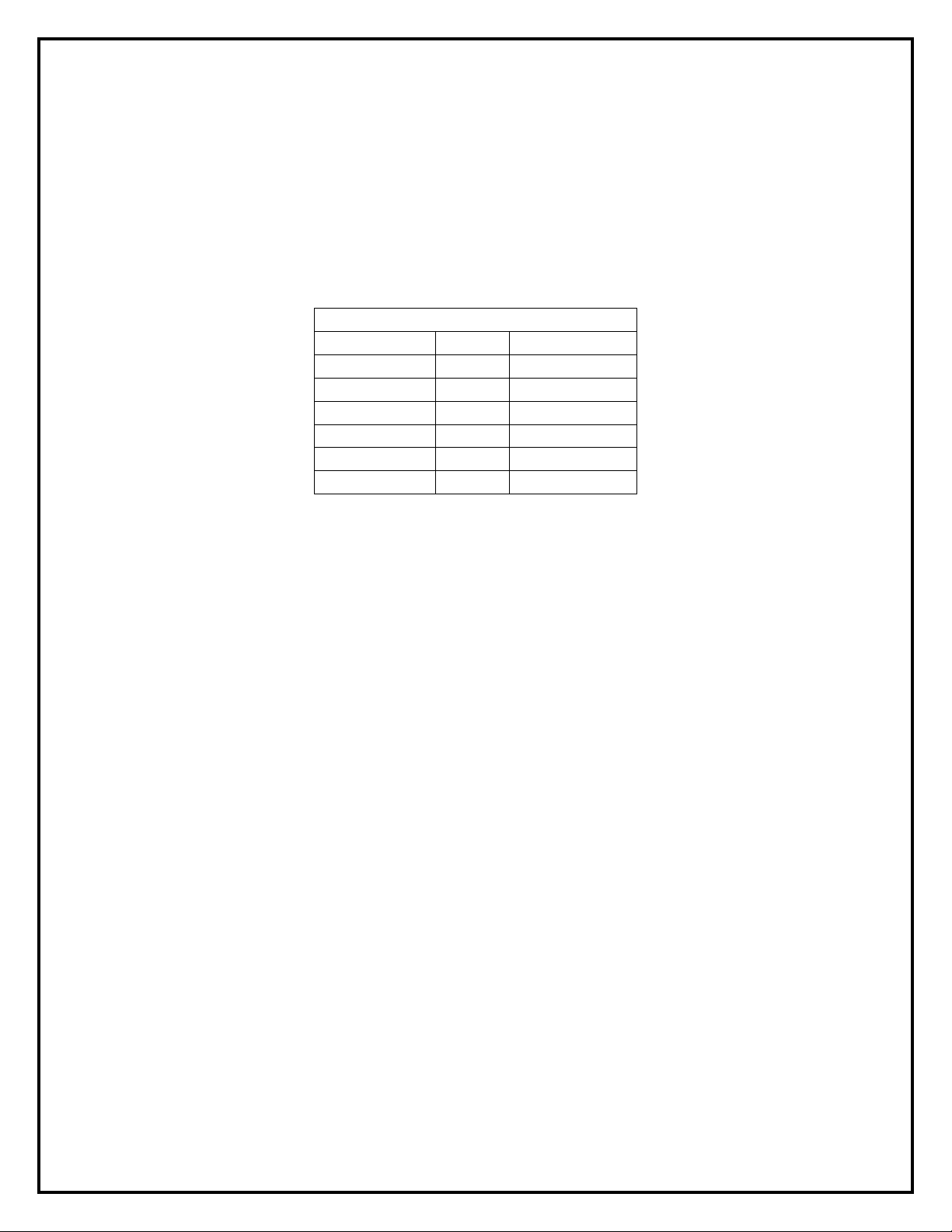
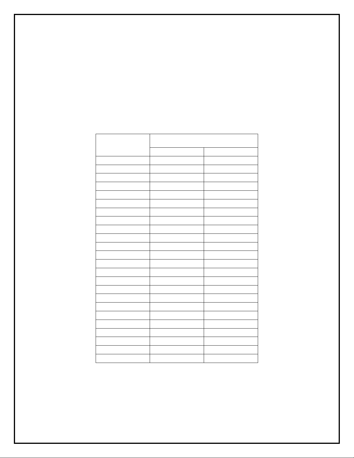
Over Temperature Interlock
An over temperature interlock circuit should be used in conjunction with thermal switch to turn
off the drive to prevent filter damage due to abnormal operating conditions. The temperature
switch is normally closed and will open when an internal reactor temperature of 180°C is
reached. See Table 3-1 below for contact rating information and the drive user manual for
interconnection information.
Table 3-1: Over Temperature Switch
opens at 180 Deg. +/- 5 Deg. C
MTE highly recommends the use of the over temperature switch to prevent damage to the filter
in rare instances of overheating from abnormal operating conditions.
9 mtecorp.com Form: MAP-IG-E June 2020 Rev 005
Page 10

Matrix® AP Installation G uid e 2 08V-690V
Power Wiring Connection
Input and output power wiring to the filter should be performed by
authorized personnel in accordance with the NEC and all local electrical
codes and regulations.
Cable lugs and mounting hardware are provided by the customer.
WARNING
Verify that the power source to which the filter is to be connected is in agreement with the
nameplate data on the filter. A fused disconnect switch or circuit breaker should be installed
between the filter and its source of power in accordance with the requirements of the NEC and
all local electrical codes and regulations. Refer to the drive user manual for selection of the
correct fuse rating and class.
For panel mounted filter applications, interconnection between the filter, its power source, the
cap-panels, and the drive is shown in Figure 3-2 (p12).
Wire gauge range and terminal torque requirements as well as selecting conductors that
interconnect the HMR and capacitor assemblies are shown in Table 3-3 (p19) for 240V, Table
3-4 (p20) for 380V - 600V, and Table 3-5 (p22) for 690V.
Refer to the drive user manual for instructions on interconnecting the drive and motor and the
correct start-up procedures for the drive.
The filter is designed for use with copper conductors with a minimum temperature rating of 75
degrees C.
For filters supplied in general purpose NEMA 1/2 & NEMA 3R cabinets, interconnection
between the filter, its power source, and the drive is shown in Figure 3-3 (p13).
Wiring Checks
Using Figure 3-1 (p11), visually check the wired components to confirm, verify, and correct
wiring. Then, with a multi meter check phase to phase isolation using the 100 K ohm range. The
multi meter will read the parallel equivalent of the bleeder resistors after the capacitors initially
charge. All phase to phase resistance values should be the same.
Check for the Following Faults:
• Capacitor shorted
• Capacitor bus not connected
• Capacitor bus to chassis short
• Paralleling wiring errors
Any extremely low or high resistance readings indicate miswiring and
may result in damage to filter components if not corrected.
On NEMA 3R enclosures, CAB-26AP and larger, no live parts shall be
mounted below 8 inches from the bottom of the enclosure.
Form: MAP-IG-E June 2020 Rev 005 mtecorp.com 10
Page 11
Matrix® AP Installation G uid e 2 08V-690V
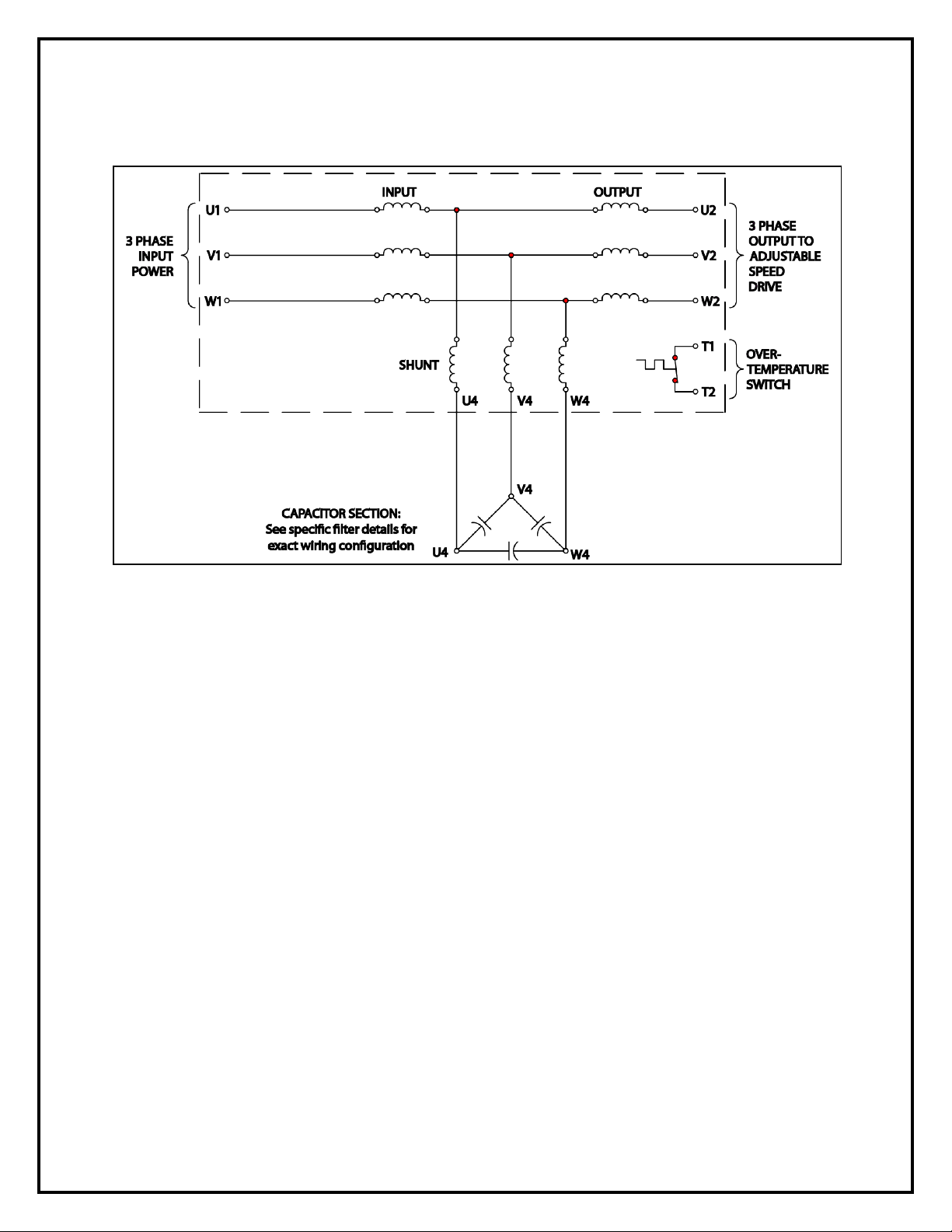
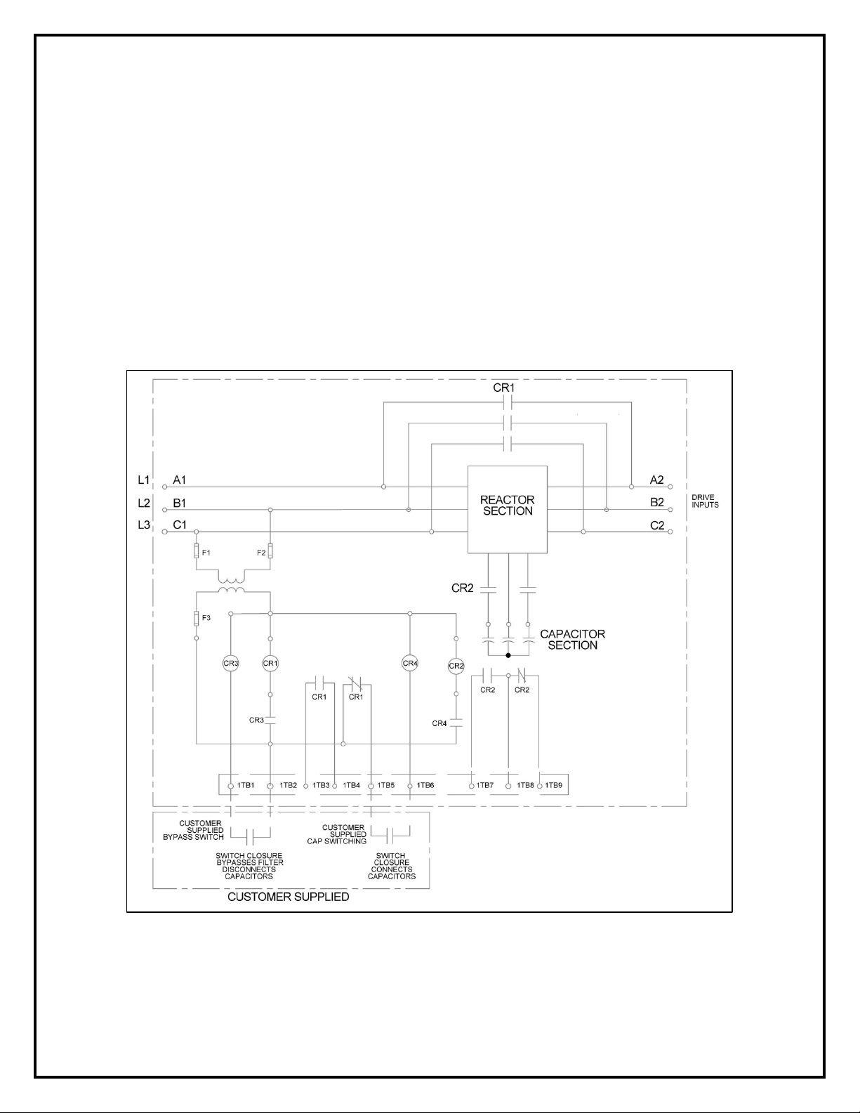
Basic Schematic Diagram
Figure 3-1: Basic Schematic Diagram
Note: Drawing depicts delta configuration for capacitors, 690V filters are connected in a WYE
configuration.
11 mtecorp.com Form: MAP-IG-E June 2020 Rev 005
Page 12

Matrix® AP Installation G uid e 2 08V-690V
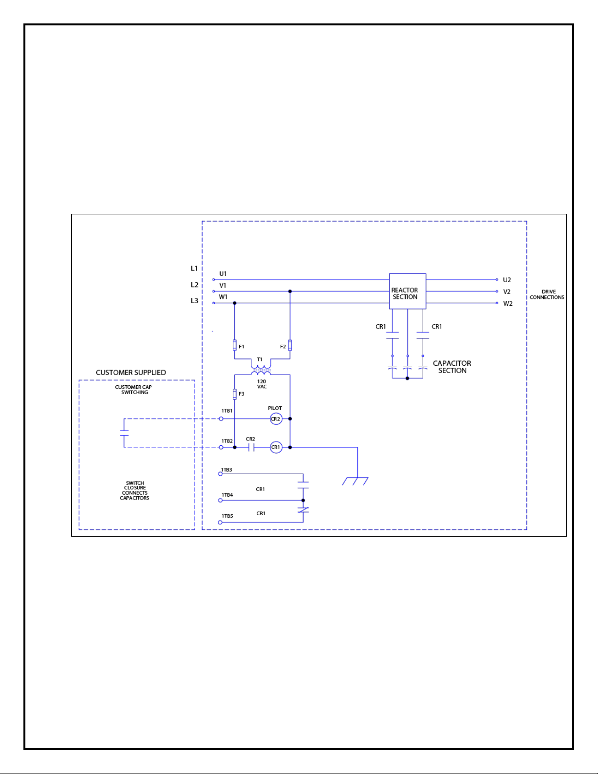
Open Panel Unit Interconnection Diagram
Figure 3-2: Open Panel Interconnection
Form: MAP-IG-E June 2020 Rev 005 mtecorp.com 12
Page 13

Matrix® AP Installation G uid e 2 08V-690V
Enclosed Unit Interconnection Diagram
Figure 3-3: Enclosed Interconnection
13 mtecorp.com Form: MAP-IG-E June 2020 Rev 005
Page 14

Matrix® AP Installation G uid e 2 08V-690V
Contactor Options
Option – 002
Capacitor Contactor
This option provides a contactor to disconnect the filter capacitor bank when the drive is not
running. The contactor is supplied with NO/NC auxiliary contacts. The contactor coil and
auxiliary contacts are wired to a customer terminal block. See page 18 for contactor coil
switching characteristics. This option is provided pre-wired complete for enclosed filters and as
loose parts for open panel filters.
Figure 3-4: Contactor Options – 002
The above contactor option diagram is pr ovided to help understand the circuit function and does
not reflect actual circuit wiring.
Form: MAP-IG-E June 2020 Rev 005 mtecorp.com 14
Page 15

Matrix® AP Installation G uid e 2 08V-690V
Contactor Options
Option – 009
Capacitor Contactor with adjustable pick up and drop out
This option provides a contactor to disconnect the filter capacitor bank based on the motor load
current. Two current operated switches provide independent adjustment of the pick-up and drop
current levels. The switches are preset at the factory for pick up at 35% and drop out at 20% of
the filter output current rating. This option is only available for enclosed filters.
Figure 3-5: Contactor Option – 009
The above contactor option diagram is pr ovided to help understand the circuit function and does
not reflect actual circuit wiring.
15 mtecorp.com Form: MAP-IG-E June 2020 Rev 005
Page 16
Matrix® AP Installation G uid e 2 08V-690V
Contactor Options
Option – 012
Capacitor contactor with control transformer
This option provides a control transformer to power the capacitor contactor. The contactor is
provided with NO/NC auxiliary contacts. For filter ratings 165 amps and above a pilot relay is
also provided to limit inrush current below 0.60 amps. Connections are wired to a customer
terminal block. This option is only available for enclosed filters.
Figure 3-6: Contact Option – 012
The above contactor option diagram is pr ovided to help understand the circuit function and does
not reflect actual circuit wiring.
Form: MAP-IG-E June 2020 Rev 005 mtecorp.com 16
Page 17
Matrix® AP Installation G uid e 2 08V-690V
Contactor Options
Option – 013
Filter bypass and capacitor contactor with control transformer
This option provides a 120 VAC control transformer to power the capacitor and bypass
contactors. Contactors are provided with NO/NC auxiliary contacts. For filter ratings 44 amps
and above pilot relays are also provided to limit inrush currents below 0.60 amps. A jumper
selection provides single contact switching for normal bypass control with capacitor removal.
Connections are wired to a customer terminal block. To incorporate this option for a selected
filter current rating use the part numbers shown below and select the option list price from the
table below. This option is only available for enclosed filters.
Figure 3-7: Contact Option – 013
The above contactor option diagram is pr ovided to help understand the circuit function and does
not reflect actual circuit wiring.
17 mtecorp.com Form: MAP-IG-E June 2020 Rev 005
Page 18
Matrix® AP Installation G uid e 2 08V-690V
AMPS
Capacitor Contactor Option 002
AMPS
INRUSH
SEALED
6
0.341
0.054
8
0.341
0.054
11
0.341
0.054
14
0.341
0.054
0.341
0.054
0.341
0.054
0.341
0.054
0.341
0.054
52
0.341
0.054
66
0.341
0.054
83
0.341
0.054
103
0.341
0.054
128
0.922
0.064
165
1.70
0.304
482
2.08
0.036
636
2.08
0.036
786
3.75
0.036
850
3.75
0.036
1000
3.75
0.036
1200
3.75
0.036
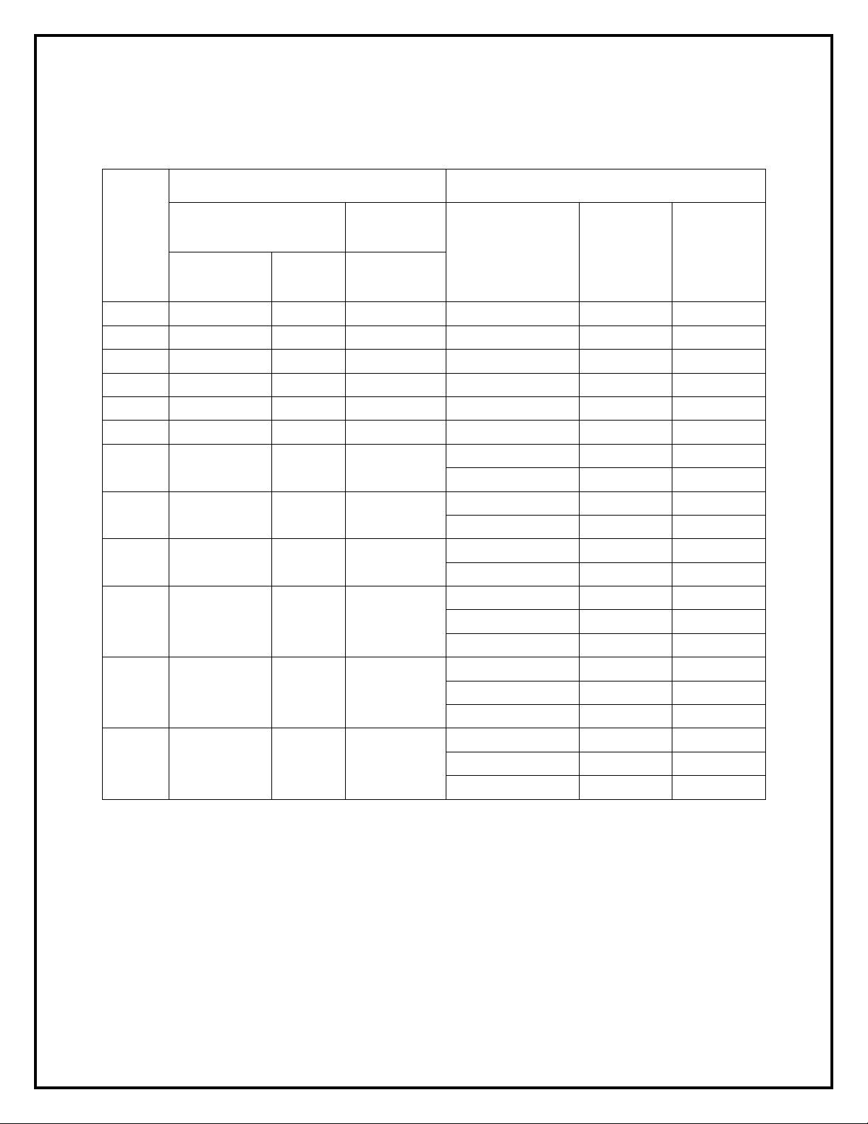
Contactor Coil Switching Currents
Option – 002
The following table indicates the 120 VAC 50/60 Hz current required to switch and hold the
various size contactors used in Matrix AP Filter capacitor switching and bypass options. This
data is provided to select the proper switch rating to remotely control the contactor and is
consistent for the 208V-240V, 380V-415V, 480V, and 600V units.
Contactor Currents for 120 VAC 60 Hz coils.
Table 3-2: Contactor Coil Switching Currents
Matrix AP filter
current Rating
21
27
34
44
208 1.70 0.304
240 2.00 0.42
320 1.41 0.025
403 1.41 0.025
Form: MAP-IG-E June 2020 Rev 005 mtecorp.com 18
Page 19

Matrix® AP Installation G uid e 2 08V-690V
Torque Ratings Matrix AP 208V-240V
Table 3-3: Torque Ratings 208V-240V
Cap-panel Terminals
U4-V4-W4
U4-V4-W4
Cap-panel
(in-lbs.)
(in-lbs.)
CAP-358TP
CAP-359TP
CAP-348TP
CAP-358TP
CAP-358TP
CAP-376TP
Matrix AP HMR Terminals
Filter
Rating
(Amps)
6 14 - 6 16 16 CAP-352TP 14 23
8 14 - 6 16 16 CAP-352TP 14 23
11 14 - 6 16 16 CAP-366TP 14 23
14 14 - 6 16 16 CAP-342TP 14 23
21 14 - 6 16 16 CAP-369TP 14 23
27 14 - 6 16 16 CAP-356TP 14 23
34 14 - 6 16 16 CAP-357TP 12 23
44 14 - 6 16 16 CAP-373TP 12 23
52 14 - 6 16 16 CAP-374TP 10 23
66 18 - 4 16 16 CAP-375TP 10 23
83 Flat copper tab 16 16 CAP-377TP 10 23
103 Flat copper tab 16 16
128 Flat copper tab 16 16
Input /Output Power
U1-V1-W1 / U2-V2-W2
Wire Range
(AWG)
Terminal
Torque
interconnect
Terminal
Torque
208V-240V
Capacitor/ Cap-panel
Part Number
Minimum
Interconnect
Wire Gauge
(AWG)
10 23
10 23
Terminal
Torque
(in-lbs.)
165 Flat copper tab 16 16
208 Flat copper tab 16 16 (2) CAP-376TP 8 23
240 Flat copper tab 16 16 CAPPANEL-153 4 60
320 Flat copper tab 16 16 CAPPANEL-154 2 60
403 Flat copper tab 16 16 CAPPANEL-155 2 60
10 23
Note: Cap-panel interconnect wiring specification according to UL508 75° C Table.
Note: To prevent flexing or bending of the coil windings attached to Matrix AP HMR Flat copper
terminal tabs, use two wrenches to tighten customer provided cable mounting hardware.
19 mtecorp.com Form: MAP-IG-E June 2020 Rev 005
Page 20

Matrix® AP Installation G uid e 2 08V-690V
Cap-panel Terminals
U4-V4-W4
U4-V4-W4
Cap-panel
Terminal
(in-lbs.)
Terminal
(in-lbs.)
Torque Ratings Matrix AP 380V-415V, 480V, 600V
Table 3-4: Torque Ratings 380V-415V, 480V, 600V
Matrix AP HMR Terminals
Filter
Rating
(Amps)
6 14 - 6 16 16 CAP-350TP CAP-338TP CAP-361TP 14 23
8 14 - 6 16 16 CAP-351TP CAP-339TP CAP-362TP 14 23
11 14 - 6 16 16 CAP-352TP CAP-349TP CAP-363TP 14 23
14 14 - 6 16 16 CAP-353TP CAP-340TP CAP-364TP 14 23
21 14 - 6 16 16 CAP-342TP CAP-341TP CAP-365TP 14 23
27 14 - 6 16 16 CAP-354TP CAP-342TP CAP-366TP 14 23
34 14 - 6 16 20 CAP-355TP CAP-343TP CAP-367TP 12 23
44 18 - 4 16 20 CAP-356TP CAP-344TP CAP-368TP 12 23
52
66
83
103
128
Input /Output Power
U1-V1-W1 / U2-V2-W2
Wire Range
(AWG)
Flat copper tab
Flat copper tab
Flat copper tab
Flat copper tab
Flat copper tab
Torque
N/A 20 CAP-357TP CAP-345TP CAP-369TP 10 23
N/A 50 CAP-358TP CAP-346TP CAP-370TP 10 23
N/A 16 CAP-359TP CAP-347TP CAP-371TP 10 23
N/A 16 CAP-360TP CAP-348TP 567(C) 8 23/60
N/A N/A 621(C) 555(C) 568(C) 8 60
interconnect
Torque
380V-415V
Capacitor/
Cap-panel
Part
Number
480V
Capacitor/
Cap-panel
Part Number
600V
Capacitor/
Cap-panel
Part Number
Minimum
Interconnect
Wire Gauge
(AWG)
Terminal
Torque
(in-lbs.)
165
208
240
320
403
482
636
786
850
Flat copper tab
Flat copper tab
Flat copper tab
Flat copper tab
Flat copper tab
Flat copper tab
Flat copper tab
Flat copper tab
Flat copper tab
N/A N/A 544(C) 557(C) 570(C) 6 60
N/A N/A 543(C) 545(C) 572(C) 4 60
N/A N/A 595(C) 544(C) 574(C) 4 60
N/A N/A 596(C) 543(C) 576(C) 2 60
N/A N/A 597(C) 562(C) 578(C) 1/0 60
N/A N/A
N/A N/A
N/A N/A
N/A N/A
595(C) 544(C) 574(C) 4 60
595(C) 544(C) 574(C) 4 60
596(C) 543(C) 576(C) 2 60
596(C) 543(C) 576(C) 2 60
597(C) 562(C) 578(C) 1/0 60
597(C) 562(C) 578(C) 1/0 60
596(C) 543(C) N/A 2 60
596(C) 543(C) N/A 2 60
595(C) 544(C) N/A 4 60
Form: MAP-IG-E June 2020 Rev 005 mtecorp.com 20
Page 21

Matrix® AP Installation G uid e 2 08V-690V
Cap-panel Terminals
U4-V4-W4
U4-V4-W4
Cap-panel
Terminal
(in-lbs.)
Terminal
(in-lbs.)
Matrix AP HMR Terminals
Filter
Rating
(Amps)
1000
1200
1600
2000
Input /Output Power
U1-V1-W1 / U2-V2-W2
Wire Range
(AWG)
Flat copper tab
Flat copper tab
Flat copper tab
Flat copper tab
Torque
N/A N/A
N/A N/A
N/A N/A
N/A N/A
interconnect
Torque
380V-415V
Capacitor/
Cap-panel
Part
Number
596(C) 543(C) N/A 2 60
596(C) 543(C) N/A 2 60
596(C) 561(C) N/A 2 60
597(C) 562(C) N/A 1/0 60
597(C) 562(C) N/A 1/0 60
597(C) 562(C) N/A 1/0 60
N/A 563(C) N/A 1/0 60
N/A 563(C) N/A 1/0 60
N/A 563(C) N/A 1/0 60
N/A 563(C) N/A 1/0 60
N/A 563(C) N/A 1/0 60
N/A 563(C) N/A 1/0 60
N/A 563(C) N/A 1/0 60
480V
Capacitor/
Cap-panel
Part Number
600V
Capacitor/
Cap-panel
Part Number
Minimum
Interconnect
Wire Gauge
(AWG)
Terminal
Torque
(in-lbs.)
N/A 563(C) N/A 1/0 60
N/A 563(C) N/A 1/0 60
N/A 562(C) N/A 1/0 60
N/A 562(C) N/A 1/0 60
2300
Flat copper tab
N/A N/A
N/A 562(C) N/A 1/0 60
N/A 562(C) N/A 1/0 60
N/A 562(C) N/A 1/0 60
N/A 562(C) N/A 1/0 60
Note: Cap-panel numbers designated with “(C)” as a suffix indicate cap-panels will be either –xxx
or –xxxC.
Note: Cap-panel interconnect wiring specification according to UL508 75° C Table.
Note: To prevent flexing or bending of the coil windings attached to Matrix AP HMR Flat copper
terminal tabs, use two wrenches to tighten customer provided cable mounting hardware.
21 mtecorp.com Form: MAP-IG-E June 2020 Rev 005
Page 22
Matrix® AP Installation G uid e 2 08V-690V
Cap-panel Terminals
U4-V4-W4
U4-V4-W4
Cap-panel
Terminal
(in-lbs.)
Terminal
(in-lbs.)
Torque Ratings Matrix AP 690V
Table 3-5: Torque Ratings - 690V
Matrix AP HMR Terminals
Filter
Rating
(Amps)
52 Flat copper tab N/A N/A CAPPANEL-622(C) 12 60
66 Flat copper tab N/A N/A CAPPANEL-612(C) 10 60
83 Flat copper tab N/A N/A CAPPANEL-613(C) 10 60
103 Flat copper tab N/A N/A CAPPANEL-615(C) 8 60
128 Flat copper tab N/A N/A CAPPANEL-617(C) 8 60
165 Flat copper tab N/A N/A CAPPANEL-619(C) 8 60
208 Flat copper tab N/A N/A
240 Flat copper tab N/A N/A
320 Flat copper tab N/A N/A
403 Flat copper tab N/A N/A
482 Flat copper tab N/A N/A
636 Flat copper tab N/A N/A
Input /Output Power
U1-V1-W1 / U2-V2-W2
Wire Range
(AWG)
Torque
interconnect
Torque
690V
Capacitor/ Cap-
panel Part
Number
CAPPANEL-614(C) 8 60
CAPPANEL-616(C) 8 60
CAPPANEL-616(C) 8 60
CAPPANEL-617(C) 8 60
CAPPANEL-618(C) 6 60
CAPPANEL-618(C) 6 60
CAPPANEL-614(C) 8 60
CAPPANEL-618(C) 6 60
CAPPANEL-618(C) 6 60
CAPPANEL-618(C) 6 60
CAPPANEL-618(C) 6 60
CAPPANEL-618(C) 6 60
CAPPANEL-620(C) 4 60
CAPPANEL-621(C) 4 60
CAPPANEL-621(C) 4 60
Minimum
Interconnect
Wire Gauge
(AWG)
Terminal
Torque
(in-lbs.)
Note: Cap-panel numbers designated with “(C)” as a suffix indicate cap-panels will be either –xxx
or –xxxC.
Note: Cap-panel interconnect wiring specification according to UL508 75° C Table.
Note: To prevent flexing or bending of the coil windings attached to Matrix AP HMR Flat copper
terminal tabs, use two wrenches to tighten customer provided cable mounting hardware.
Form: MAP-IG-E June 2020 Rev 005 mtecorp.com 22
Page 23

Matrix® AP Installation G uid e 2 08V-690V
4. START UP
Startup Checklist
Safety Precautions
Before startup, observe the following warnings and instructions:
Internal components of the fi lter a re a t li ne potentia l w he n t he fil ter is c onnec ted
to the drive. This voltage is extremely da ngerous and may cause deat h or severe
injury if you come i n c ontact w ith i t.
Remove all power to the Mat rix AP f il ter i n c omplia nce to s ta ndardi ze d 26 C FR
1920.147 lockout/ta gout pol ic ies. Af ter re movi ng pow e r, a llow a t leas t five
minutes to elapse and verify that the capacitors have discharged to a safe level
before contacting internal components. Connect a DC v oltmeter across the
capacitor terminals and ensure that the voltage is at a safe level. Sta rt with the
WARNING
meter on the highest scale and progressively switch to a lower scale as the
indicated voltage falls below t he maximum value of the scale used.
Use extreme caution to av oi d contac t with l i ne volt a ge when c hecki ng f or pow er .
INJURY OR DEATH MAY RESULT IF SAFETY PRECAUTIONS ARE NOT
OBSERVED.
Damage to equipment may occur if the drive startup procedures are not
observed.
23 mtecorp.com Form: MAP-IG-E June 2020 Rev 005
Page 24

Matrix® AP Installation G uid e 2 08V-690V
Sequence of Operation
1. Read and follow safety precautions.
2. After installation, ensure that:
• All filter ground terminals are connected to ground.
• Power wiring to the utility, drive and motor is in accordance with the power wiring
connection diagrams shown in installation inst ructions section. Use the guidelines
of Table 3-3 (p19) for 208V-240V, Table 3-4 (p20) for 380V - 600V and Table 3-5
(p22) for 690V, for power and cap-p anel wire gauges.
3. Check that moisture has not condensed on the filter components. If moisture is present,
do not proceed with startup until the moisture has been removed.
4. Disconnect the filter output from the drive.
5. Connect the filter t o the utility.
6. Confirm that line voltage is present at the input terminals (U 1, V1, W1) of the filter.
7. Confirm that drive vo ltage is present at the output terminals (U2, V2, W2) of the filter and
that it is equal to 1.05 times the input voltage with capacit o rs in circuit.
8. Using a clamp on Am p me t er, check input phase currents to verify they are wi thin a 5%
match to each ot her and approximately 30% of filter current rating.
9. Remove power and verify that NO VOLTAGE is present on the filter terminals.
10. Connect the filter output to the drive.
11. Refer to the drive user manual for the drive startup procedure. Observe all safety
instructions in the drive user manual.
Form: MAP-IG-E June 2020 Rev 005 mtecorp.com 24
Page 25
Matrix® AP Installation G uid e 2 08V-690V
5. TROUBLESHOOTING
INJURY OR DEATH MAY RESULT IF THE DRIVE SAFETY PRECAUTIONS ARE
NOT OBSERVED.
When properly installed, this equi pment has been des igned to provide maximum
safety for operating personnel.
However, hazardous voltages and elevated temperatures exist within the
WARNING
Caution
To aid in troubleshooting, a basic schematic diagram, two interconnec tion diagram s, and a
troubleshooting guide that lists potential problems a nd solu tions are included:
confines of the enc los ure. Se rvici ng s houl d t here fore be perf ormed by qualified
personnel only and i n acc or dance w ith O SHA Re gulati ons.
High voltage is use d in t he ope rati on of t his fi lte r. Use Ex tre me ca uti on t o avoid
contact with high voltage when operati ng, i nstal li ng or re pai ri ng this filter.
INJURY OR DEATH MAY RESULT IF SAFETY PRECAUTIONS ARE NOT
OBSERVED.
After removing power, allow at least five minutes to elapse and verify t hat the
capacitors have discharged to a safe level before contacting internal
components. Connect a DC voltmeter across the capacitor terminals or
terminals U1, V1or V1, W1 and ensure that the voltage is at a safe level.
Figure 3-1: Basic Schematic Diagram (p11)
Figure 3-2: Open Panel Interconnection (p12)
Figure 3-3: Enclosed Interconnection (p13)
Table 5-2: Troubleshooting Guide (p28)
25 mtecorp.com Form: MAP-IG-E June 2020 Rev 005
Page 26
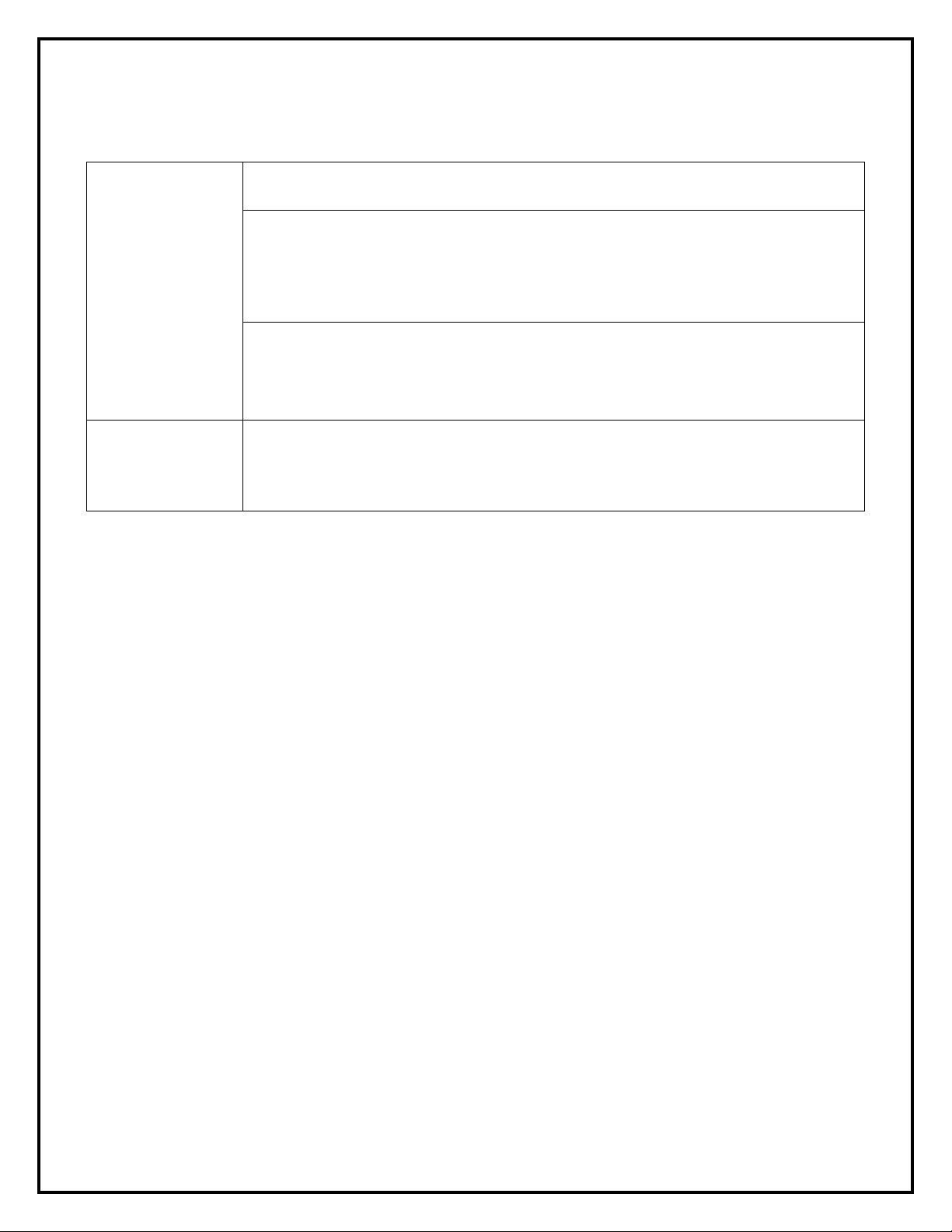
Matrix® AP Installation G uid e 2 08V-690V
Service Load Condition
Load: 6-pulse rectifier only
208V-240V +/- 10%; 60 + 0.75 Hz; 3-phase
690V +/- 10%; 50 + 0.75Hz; 3-phase
Maximum THID
8% @ 30% Load; 5% @ Full Load
-40C to +50C Open Panel Filters
-40C to +90C Storage
Insertion Loss @ Full Load
<4%
Efficiency
97% - 99%
Altitude without derating
3,300 feet above sea level
Relative Humidity
0% to 95% non-condensing
Current Rating
150% for 1 minute
Matrix AP Performance Data
For specific product performance specifications, reference Table 5-1 below:
Table 5-1: Performance Specifications
380V - 415V +/- 10%; 50 + 0.75Hz; 3-phase
Input Voltage
480V +/- 10%; 60 + 0.75Hz; 3-phase
600V +/- 10%; 60 + 0.75Hz; 3-phase
Maximum Ambient
Temperature
Generator sizing note: Generator sizing is best completed by sizing programs or help from a
generator manufacturing representative. Identify every load type and size that will be powered
from the generator. If non-linear loads are present the generator may need to be oversized.
Generator rated KVA minimum load >= Matrix rated current x √ 3 generator voltage
FLA load current <= Matrix filter rated current
Notes (SCCR):
The Short Circuit Current Rating (SCCR) is not required under Exception No.1 of
UL508A SB4.2.1 effective 4/25/06. This exception also applies to all the Contactor
Options (002, 009, 012, and similar), where the Contactors are separated from the
Main Power path by exempt components (such as Reactors) of sufficient
Impedance, which is assured in case of the Reactors that are integral
components of our Filter.
-40C to +40C – 45C Enclosed Filters
Form: MAP-IG-E June 2020 Rev 005 mtecorp.com 26
Page 27

Matrix® AP Installation G uid e 2 08V-690V
Matrix AP Harmonic Filter Field Checks
1. Read and understand the Matrix AP Technical Reference Manual which can be
downloaded at www.mtecorp.com/matrix-ap-documentation/
drawings for your particular filter and identify the terminal locations.
2. Disconnect all power and remove input power wiring from U1, V1, W1 terminals.
3. Remove VFD drive power connections from filter terminals U2, V2, W2 and any
contactor or temperature switch wiring. (For filters using control transformers: remove
power fuses on top of transformer.)
4. Visually inspect filter terminals and wiring lugs for signs of heat and corrosion. Contact
factory if any wires appear to be missing or cut!
5. Inspect the U4, V4, W4 capacitor interconnect terminals and wiring.
6. Visually inspect all capacitors for signs of case deformation, bowing of the top, leaking
oil or terminal damage. Note the CAP- # and date code of any damaged capacitors.
7. Using a multi meter set to read 100K ohms check:
a. Phase to phase U1-V1-W1-U1 (mechanically activate contactor if present) after
reactor and caps charge reading should be about 40K (total equivalent breeder
resistance value) and should be the same for each phase. Open circuit or very
low readings indicate a problem.
b. Phase to chassis U1- case, V1-case, W1- case; low readings indicate a ground
fault problem.
8. Ensure the “disconnect” is safe then wire the utility power to U1, V1, W1.
9. Apply power and verify that proper output voltage is present on U2, V2, and W2.
10. Using a clamp on amp meter read the filter input current:
a. Readings will be 0.5 of the capacitor current listed in the Matrix AP Technical
Reference Manual found at www.mtecorp.com/matrix-ap-documentation/
(mechanically activate the contactor if the filter is equipped with one). Readings
should be the same (+/- 5%) for all phase currents; contact the factory if
currents are out of tolerance!
b. Open contactor readings will show zero current for all phases.
11. Disconnect filter power and wire the VFD to U2, V2, and W2 as well as any control
wiring to the filter contactor or temperature switch. Replace any control transformer
fuses. Follow the drive power startup guidelines in the drive manufacturer’s user manual.
. Locate figures and
27 mtecorp.com Form: MAP-IG-E June 2020 Rev 005
Page 28

PROBLEM:
Line voltage is not present at the filter output terminals.
Possible cause:
Power to the filter is turned off.
Solution:
Turn power on.
Possible cause:
One or more external line fuses are blown.
Solution:
Verify the continuity of line fuses in all phases. Replace as necessary.
PROBLEM:
Full Load Harmonic current distortion exceeds 5% on one or more
phases at full load.
Possible cause:
The capacitor assembly has not been connected.
Check interconnection of capacitor assembly per the following:
Possible cause:
A capacitor has failed.
Solution:
Inspect the tops of all capacitors for bowing. Replace failed capacitors.
Possible cause:
Source impedance is less than 1.5%.
Solution:
Add a minimum 1.5% impedance line reactor to the filter input.
Identify equipment causing harmonic voltage distortion and add filters as
required or accept elevated THVD.
Possible cause:
Line voltage unbalance exceeds 1%.
Solution:
Balance input line voltage to 1% or less.
PROBLEM:
Filter output voltage is not within specification
Possible cause:
Filter input voltage is not within specification.
Check the AC input line voltage and verify that it is within tolerance. Refer
tolerances.
Possible cause:
Source impedance is out of tolerance.
Verify that the source impedance is within tolerance. Refer to the filter
service conditions and performance specifications for tolerances.
Possible cause:
Source impedance is out of tolerance.
Verify that the source impedance is within tolerance. Refer to the filter
service conditions and performance specifications for tolerances.
Possible cause:
One or more Capacitors is damaged.
Visually check capacitor top for distortion or doming. Check for shorts or
open caps. Replace failed capacitors.
Possible cause:
Drive set up parameter does not allow for input filter
Solution:
Consult drive manufacturer to update setup to accommodate input filter.
Input voltage subject to extreme tran sients such as switching between
two voltage sources. Drive faults on over or under voltage.
Source switching is not recommended without proper phase
source.
Matrix® AP Installation G uid e 2 08V-690V
Table 5-2: Troubleshooting Guide
Solution:
Figure 3-2: Open Panel Interconnection (p12)
Figure 3-3: Enclosed Interconnection (p13)
Possible cause: Input source voltage harmonic distortion.
Solution:
Figure 3-1: Basic Schematic Diagram (p11)
Solution:
to the filter service conditions and performance specifications for
Solution:
Solution:
Solution:
Possible cause:
Solution:
synchronizing or allowing reasonable time delay before transfer to new
Form: MAP-IG-E June 2020 Rev 005 mtecorp.com 28
 Loading...