

MTE HYDROCAL 1001 Plus Installation And Operation Manual

HYDROCAL 1001+ Installation and operation manual Edition RS485 01.2015
HYDROCAL 1001+
Composite Gas-in-Oil Sensor with
Moisture in Oil Measurement
Installation and operation manual

HYDROCAL 1008 Manual for Installation and Operation Page 2/114
MTE Meter Test Equipment AG
Dammstrasse 16
CH-6304 Zug
Switzerland
Phone: +41-41-724 24 48
Fax: +41-41-724 24 25
Email: support@mte.ch
EMH Energie-Messtechnik GmbH
Vor dem Hassel 2
D-21438 Brackel
Germany
Phone: +49-4185-5857-0
Fax: +49-4185-5857-68
Email: info@emh.de
Copyright MTE Meter Test Equipment AG
All rights reserved.
The contents of this manual are
subject to change without notice.
All efforts have been made to ensure
the accuracy of this publication but
MTE Meter Test Equipment AG can
assume no responsibility for any errors Customs tariff number:
or their consequences 9027.1010

HYDROCAL 1001 Manual for Installation and Operation Page 1/72
Table of Content
1. General..................................................................................................................................... 3
2. Installation instructions .......................................................................................................... 4
2.1. Installation positions ............................................................................................................. 4
2.2. Safety precautions ................................................................................................................ 5
2.3. Installation preparation ......................................................................................................... 7
2.3.1. Mechanical connection .................................................................................................. 7
2.3.1.1. Flange connection .................................................................................................. 7
2.3.1.2. Fitting with union nut ............................................................................................... 7
2.3.2. Auxiliary supply connection ........................................................................................... 8
2.3.3. Required tools ............................................................................................................... 8
2.3.4. Sealing the connection thread ....................................................................................... 8
2.3.4.1. Thread seal tape..................................................................................................... 8
2.3.4.2. Thread sealant ....................................................................................................... 9
2.3.4.3. Flat sealing (gasket) ............................................................................................... 9
2.4. Installation .......................................................................................................................... 10
2.4.1. Mechanical installation ................................................................................................. 10
2.4.1.1. Direct installation .................................................................................................. 11
2.4.1.2. Indirect installation ................................................................................................ 12
2.4.2. Electrical connection .................................................................................................... 14
2.4.3. Putting into operation ................................................................................................... 15
3. Hardware components .......................................................................................................... 16
3.1. Front view ........................................................................................................................... 16
3.2. Rear view ........................................................................................................................... 17
3.3. Connections of measurement- and controller card .............................................................. 19
3.3.1. Beeper ......................................................................................................................... 22
3.4. Connections of power supply card ...................................................................................... 23
3.5. Wiring of the heating resistors ............................................................................................ 24
3.5.1. Wiring heating resistors for 230 V ................................................................................ 25
3.5.2. Wiring heating resistors for 120 V ................................................................................ 26
4. Firmware ................................................................................................................................ 27
4.1. General information ............................................................................................................ 27
4.2. External user interface ........................................................................................................ 27
4.2.1. Function LED .............................................................................. 28
4.2.2. Gas LED ..................................................................................... 28
4.2.3. Moisture LED .............................................................................. 30
4.3. Internal user interface ......................................................................................................... 31
4.3.1. Normal Operation ........................................................................................................ 32
4.3.1.1. LED & energy save mode ..................................................................................... 32
4.3.1.2. LED Ethernet ........................................................................... 32
4.3.1.3. LED RS485 ............................................................................. 32
4.3.1.4. LED Gas analog output .......................................................... 33
4.3.1.5. LED Moisture analog output .................................................... 33

HYDROCAL 1001+ Installation and operation manual Page 2/76
4.3.1.6. LED bar level - Gas .................................................... 34
4.3.1.7. LED bar levels - Moisture ........................................... 46
4.3.2. Special Operation ........................................................................................................ 47
4.3.2.1. Unit Power-On - Boot ........................................................................................... 47
4.3.2.2. Update of Firmware - Downloader ........................................................................ 48
4.3.2.3. Update of Firmware - via TFTP ............................................................................. 50
4.3.2.4. Functional Test ..................................................................................................... 51
4.3.2.5. Test Mode ............................................................................................................ 53
4.3.3. Communication Interface Reset ................................................................................... 56
4.4. Default Communication Interface Setup.............................................................................. 57
4.5. Establish a Point-to-Point Ethernet Connection .................................................................. 58
4.5.1. Setup HYDROCAL 1001+ ........................................................................................... 58
4.5.2. Change of TCP/IP Settings on the PC ......................................................................... 58
4.5.2.1. Navigating to the Network Adapter Properties ...................................................... 59
4.5.2.2. Changing the Network Adapter Properties ............................................................ 61
4.5.3. Test of Communication with Hydrosoft ........................................................................ 62
4.5.4. Diagnosis / Trouble Shooting ....................................................................................... 63
4.5.4.1. Basic Checks ........................................................................................................ 63
4.5.4.2. Check of PC Network Adapter Setup .................................................................... 63
4.5.4.3. Low Level Connection Test (PING) ...................................................................... 64
4.6. Communication setup ......................................................................................................... 65
4.6.1. RS485 setup ................................................................................................................ 65
4.6.1.1. Point-to-Point ........................................................................................................ 65
4.6.1.2. Bus Node ............................................................................................................. 66
4.6.1.3. MODBUS RTU ..................................................................................................... 67
4.6.1.4. MODBUS ASCII ................................................................................................... 68
4.6.2. ETHERNET setup ....................................................................................................... 69
4.6.2.1. Static IP ................................................................................................................ 69
4.6.2.2. DHCP Client ......................................................................................................... 70
4.6.3. MODBUS® TCP ........................................................................................................... 71
4.6.3.1. Function, Register and Address Mapping ............................................................. 71
5. Technical data ....................................................................................................................... 73
6. Dimensional Drawings .......................................................................................................... 75
6.1. Dimensions of valve connection ......................................................................................... 76
6.1.1. Connection thread G 1½’’ ISO DIN 228-1 .................................................................... 76
6.1.2. Connection thread 1½’’ NPT ANSI B 1.20.1 ................................................................ 76

HYDROCAL 1001+ Installation and operation manual Page 3/76
1. General
The HYDROCAL 1001+ is a permanently installed composite gas-in-oil sensor for the analysis of
moisture in oil and the following dissolved key fault gases (TDCG = Total Dissolved Combustible
Gases):
Fault gas TDCG contribution
Hydrogen (H2) approx. 20 %
Carbon Monoxide (CO) approx. 30 %
Methane (CH4) < 5 %
Acetylene (C2H2) 100 %
Ethylene (C2H4) approx. 32 %
Ethane (C2H6) < 5 %
Moisture in Oil (H2O) 100%
To provide an even more comprehensive transformer monitoring solution, the HYDROCAL 1001+
analyses additionally the content of moisture (H2O) in the transformer oil.
The integration of 6 relevant key gases into a total weighted gas concentration and the measurement
of moisture in oil, enables the HYDROCAL 1001+ to react to most transformer faults and makes the
unit to a compact and cost effective tool used in particular for early transformer fault detection and
preventative maintenance.
The HYDROCAL 1001+ is equipped with 2 analog 0/4 ... 20 mA outputs for the dissolved composite
gas-in-oil and moisture in oil analysis results and 4 digital relay outputs (Gas high alarm, gas highhigh alarm, moisture alarm and function alarm)
Key advantages:
Composite measurement of hydrogen (H2), carbon monoxide (CO), methane (CH4), acetylene
(C2H2), ethylene (C2H4) and ethane (C2H6) and dissolved moisture (H2O) in the transformer oil
Relay outputs with light indicators showing potential alarms
Easy and fast installation without any operational interruption of the transformer
It provides communication interfaces ETHERNET 10/100Mbit/s (copper-wired or fibre-optical) and
RS485 to support proprietary communication protocols and to be prepared for sub-station communication protocols MODBUS®TCP and MODBUS® serial RTU/ASCII
The construction has been significantly simplified and size has been reduced compared to other
products in the market period.
The present operating instructions are divided in the following sections:
Installation instructions (chapter 2)
Hardware components (chapter 3)
Firmware (chapter 4)
Technical data (chapter 5)
Dimensional drawings (chapter 6)
HYDROCAL 1001+ Installation and operation manual Page 4/76
2. Installation instructions
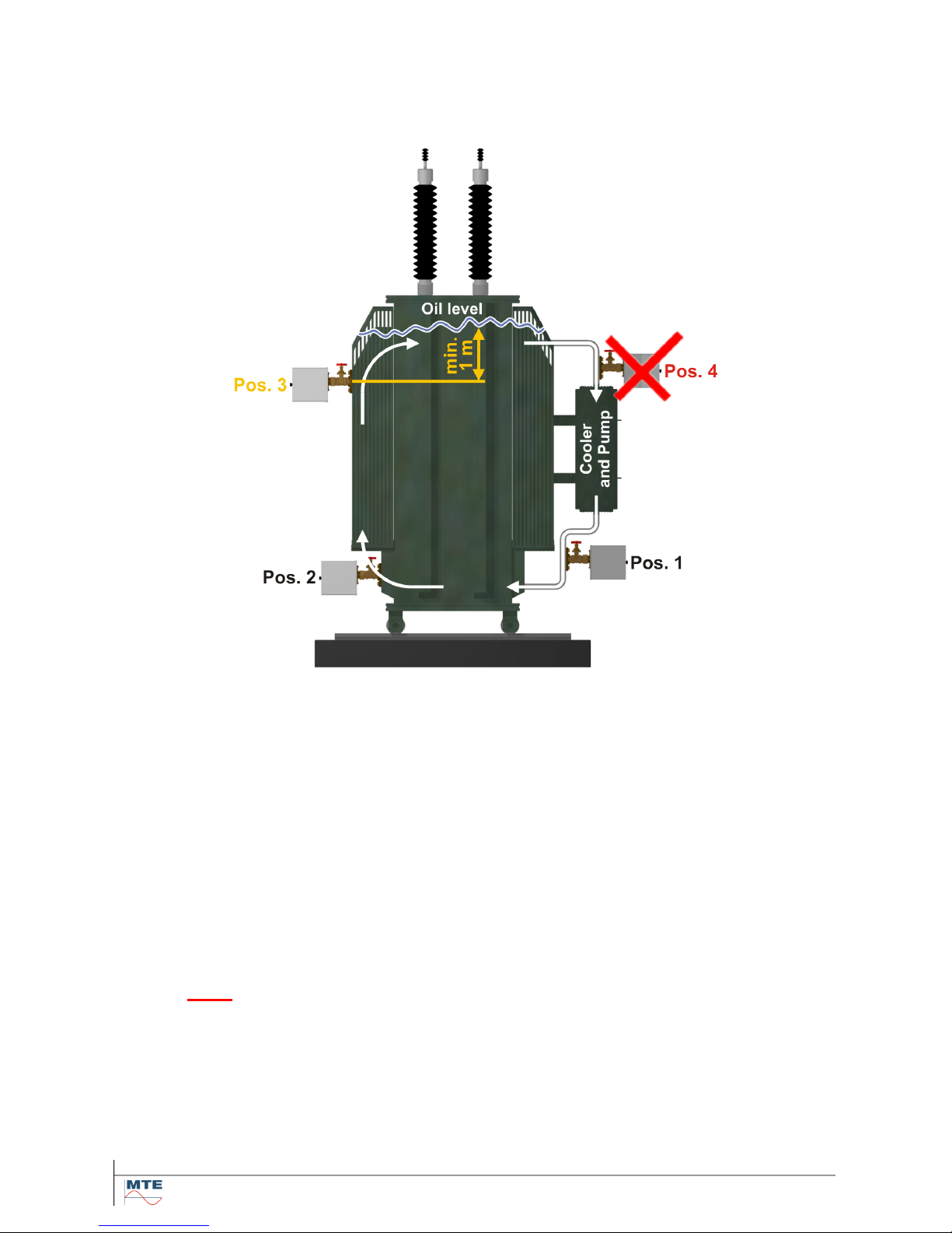
2.1. Installation positions
To ensure the correct function of a HYDROCAL unit the installation position is very important. On a
typical transformer three positions are possible:
Pos. 1
Output side of cooling unit:
Please install the unit on a straight piece of pipe on the cooler output between the cooler
and the main oil tank. In order to avoid negative pressure, the unit must absolutely be
mounted on the output of the oil circulation pump.
Note: Choose this position only if a continuous oil flux through the cooler is guaranteed
Pos. 2
Draining valve on the transformer tank:
The flange of the draining valve must be at minimum height of 40 cm in order to allow installation and mounting of HYDROCAL unit.
Pos. 3
Upper filling valve:
It is possible to mount HYDROCAL unit on this position, if the filling level of the oil is min.
100 cm higher than the center of the connection thread.
This position is not recommended, because it may be difficult to operate the unit.
Pos. 4
Input side of cooling unit:
Never install the HYDROCAL unit on top of the cooling unit or on the suction side of
the cooler pump!
Note: On the installation position a good and continuous oil circulation must be present.

HYDROCAL 1001+ Installation and operation manual Page 5/76
2.2. Safety precautions
The following security precautions must be strictly observed during the installation. Otherwise no warranty claims will be accepted.
Never remove the protection cap from the connection thread until you are
ready to mount the unit on the transformer valve.
The protection cap protects the connection unit against dust and from other
impurities. Additionally it protects the connection thread.
Note: Use the protection cap also after dismounting the unit.
Never close the aeration hole for oxygenation. It is situated on the bottom
side of the protection cover.
Never use or stock chemicals with hydrocarbon contents near the measuring sensor.
Never clean the HYDROCAL unit with solvents, because its gases will strongly
impair the measurement accuracy and the sensitivity of the sensors.
Never apply a negative pressure to the connection unit.
Negative pressure can damage the membrane.
Never touch the membrane with fingers or other objects.

HYDROCAL 1001+ Installation and operation manual Page 6/76
Remove the HYDROCAL unit from the valve every time you degas or refill
the transformer. You can also close the transformer valve.
Never operate the HYDROCAL unit on a valve that is closed for a long
period of time. Remove the unit if this cannot be avoided. Please refer to
the de-installation instructions.
Never install the HYDROCAL unit on the suction side of the cooling
pump!!
Never install the HYDROCAL unit on an elbow or curve of a tube.
Turbulences in a tube curve can create a negative pressure, which can damage the membrane.
Never install or remove the HYDROCAL unit without opening the aeration
screw first.
Never use galvanized fittings or valves to mount the HYDROCAL unit.
Galvanized fittings or valves can react with oil, this will produce incorrect
measurement values.
Never clean the HYDROCAL unit with high pressure cleaning equipment.
High pressure cleaning equipment used to clean transformers can seriously
damage the HYDROCAL unit.
Never use a chaining key tool for mounting.
Use of such tools can damage the surface of the connection unit and the
threads. Please use a tin spanner M55 or an adjustable tin spanner for 1 ½“.
Attention!!!
Faulty or inappropriate handling of the connection unit, like malfunction
by negative pressure, paint or solvent liquids make the warranty invalid.
HYDROCAL 1001+ Installation and operation manual Page 7/76
2.3. Installation preparation
Attention!!!
Always open the aeration screw first!!!
Before installation, a visual inspection of the membrane must be carried out. Open the aeration screw
3 to 4 turns while turning CCW with a long Allen key No. 4. Slowly remove the protection cap while
turning CCW and check the membrane. No cuts or tears should exist, the surface must be smooth.
Do not touch the membrane with fingers or with any other objects. Unscrew the knurled thumb
screws, remove the protection cover and check visually the components. For the installation remount
the protection cover and fasten it with the knurled thumb screw.
2.3.1. Mechanical connection
The external thread type of the HYDROCAL connection unit is even G 1½’’ ISO DIN 228-1 or
1½’’ NPT ANSI B 1.20.1 (must be specified when ordering).
The HYDROCAL unit should be installed on a gate valve with full bore or on a ball valve to the transformer.
These locking elements are usually provided with a blind flange. Therefore they must be upgraded
before mounting the HYDROCAL unit with a corresponding threaded flange, connection adapter or a
fitting with union nut.
This results in two different mounting ways (direct and indirect).
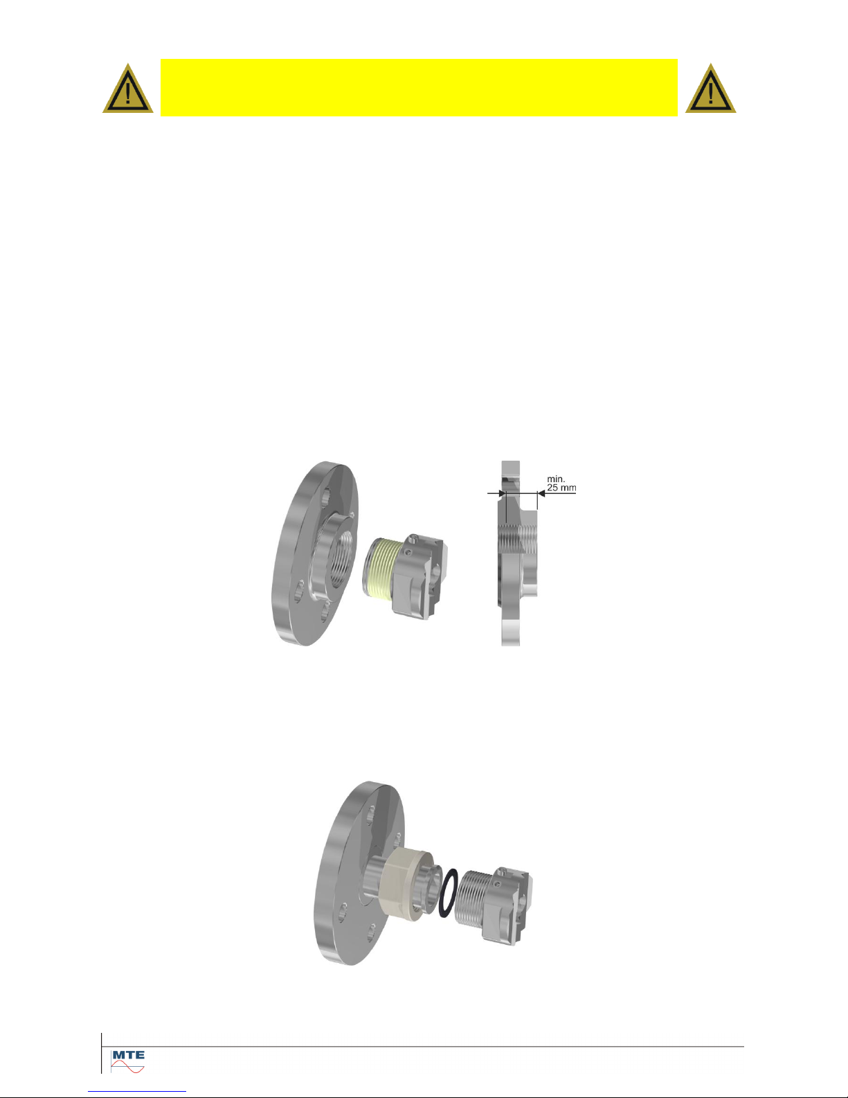
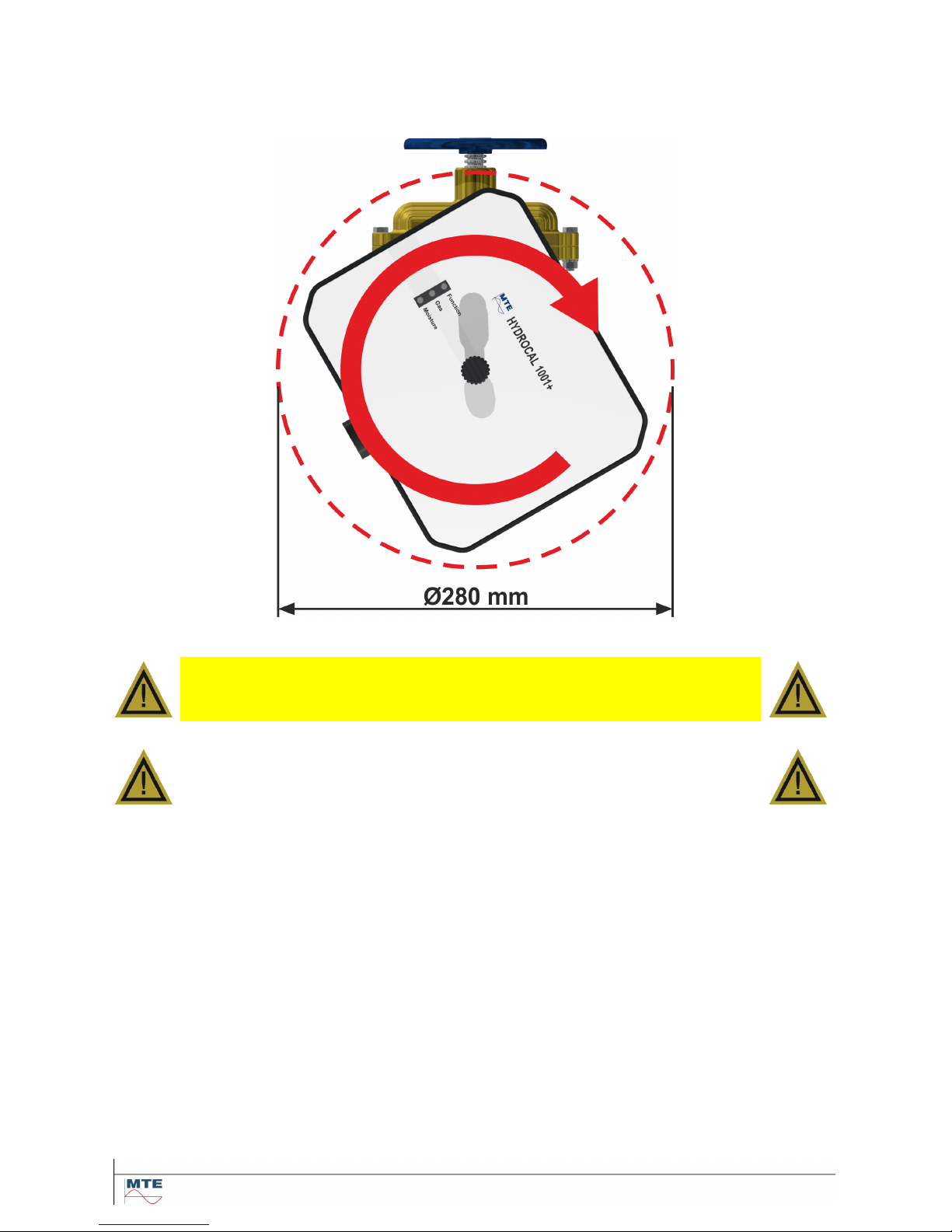
2.3.1.1. Flange connection
The unit is screwed directly onto the threaded flange, i.e. the unit is rotated around its own axis in
order to fix it. In this type of installation the space around the center of the connection unit must be
free in a diameter of 280 mm.
Note: The thread depth of the threaded flange or the connection adapter should be at least 25 mm.
2.3.1.2. Fitting with union nut
We recommend installing the HYDROCAL unit with a fitting with union nut (flat sealing) to the transformer gate / valve. This fitting consists of a threaded flange, a flat sealing union end and a union nut.
In this case the union nut must be rotated to fix the HYDROCAL unit and a gasket is used to seal the
connection. An additional thread sealing with thread seal tape or thread sealant is not or rarely necessary in this case.
Note: Ball valves with union nut are also available (pump ball valve).
HYDROCAL 1001+ Installation and operation manual Page 8/76
2.3.2. Auxiliary supply connection
The HYDROCAL unit is available in 4 different voltage versions (must be specified when ordering).
Depending on the used nominal voltage version there must be an AC or DC power supply with a 3
pin power cable (2.4.2) close to the HYDROCAL unit:
Nominal voltage version HYDROCAL
Auxiliary supply voltage
120 V -20% +15% AC 50/60Hz
96 V
min
... 138 V
max
AC 50/60Hz
230 V -20% +15% AC 50/60Hz
184 V
min
... 264 V
max
AC 50/60Hz
120 V -20% +15% DC
96 V
min
... 138 V
max
DC
230 V -20% +15% DC
184 V
min
... 264 V
max
DC
The power consumption of the HYDROCAL 1001+ unit is max. 250 VA.
Micro-fuse: 120V: T3.15A (slow blow) 230V: T2A (slow blow)
2.3.3. Required tools
The mechanical and electrical installation of the HYDROCAL unit can be executed with following
tools and utilities:
Long Allen key No. 4 Aeration screw (bleeding screw)
Digital Multimeter Checking supply voltage
Screw driver No. 2 Main connectors supply voltage cable
Brass brush Connection unit
Tin spanner M55 and / or Connection unit
adjustable tin spanner 1 ½“
Bucket, oil absorber, cleaning rag, To absorb/clean the out coming oil
paper towel
Plastic sheet To collect dropping parts
2.3.4. Sealing the connection thread
Securing and sealing the connection threads may be implemented in various ways. It should be used
either a thread seal tape or a thread sealant:
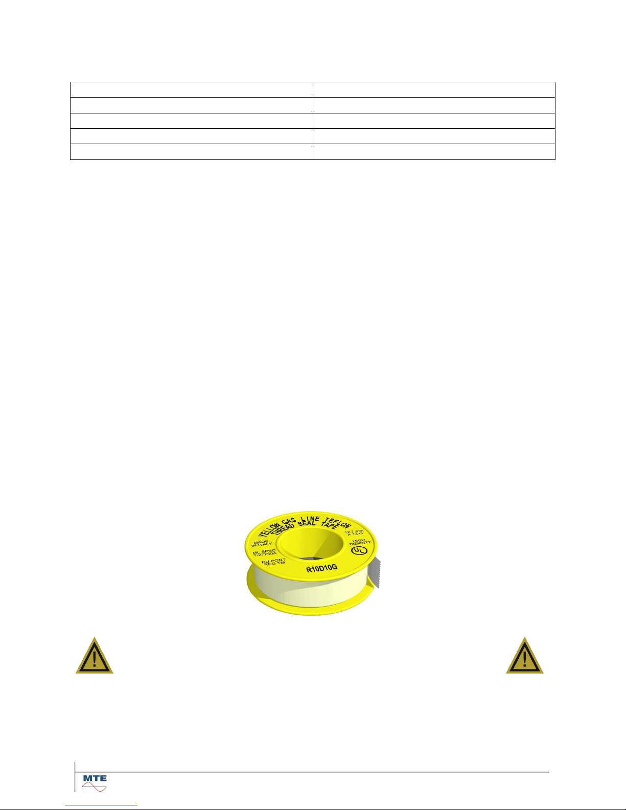
2.3.4.1. Thread seal tape
The thread seal tape, also known as Teflon tape or PTFE tape (Polytetrafluoräthylen), is wrapped
tightly around the external thread of the HYDROCAL connection unit. We recommend using a Teflon
tape for coarse thread (100g/m2).
Attention !!!
If you use Teflon tape for sealing the connection thread,
nothing can be adjusted after wards.
!!!! Risk of leakage !!!!
HYDROCAL 1001+ Installation and operation manual Page 9/76
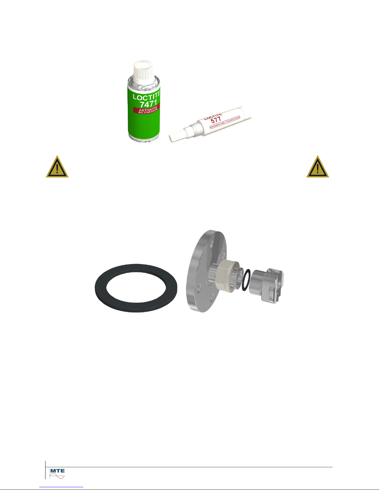
2.3.4.2. Thread sealant
As a thread sealant we recommend the two Henkel products LOCTITE® 7471 (activate) and
LOCTITE® 577 (seal and fix) in combination. The activator LOCTITE® 7471 is used to increase the
rate of cure and is applied before the actual thread adhesive LOCTITE® 577 is applied on 3 to 4 turns
of the external thread of the HYDROCAL connection unit.
Attention !!!
Please follow the instructions of the manufacturer!!!
2.3.4.3. Flat sealing (gasket)
When using a fitting with union nut the sealing and locking of the threaded connection with thread
seal tape or thread sealant is not necessary anymore. In this case the gasket serves as sealing and
the union nut as fixation of the connection.
HYDROCAL 1001+ Installation and operation manual Page 10/76
2.4. Installation
After the installation preparation is completed, the HYDROCAL unit can be installed. The installation
is divided into 3 steps:
Mechanical installation (2.4.1)
Electrical connection (2.4.2)
Putting into operation (2.4.3)
2.4.1. Mechanical installation
The sequence of the mechanical installation depends on which connection type is available on the
transformer side. There are basically 2 types of mechanical installation:
Direct installation (2.4.1.1)
Indirect installation (2.4.1.2)
Note: In case there are strong vibrations on the connection valve, the valve should be relieved by a
support.
A good oil flux should exist on the installation position. If necessary, use a reduction piece (adapter).
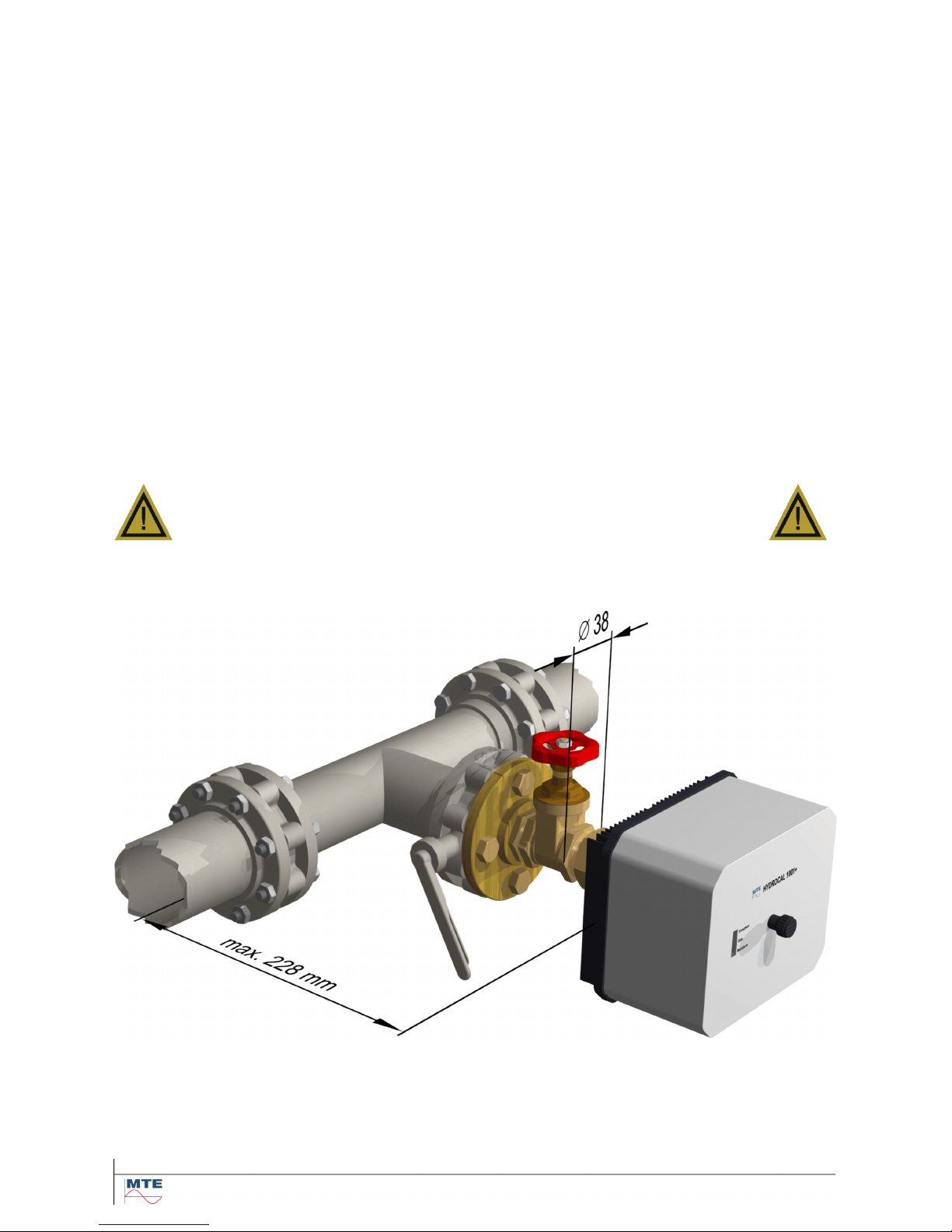
In order to have a sufficient oil flux on the membrane, the diameter of the valve should be not less
than 25 mm. For optimal working conditions, the valve diameter should not be more than 76 mm. The
valve must be on earth potential.
Attention!!!
The distance between the oil main stream and the backplate unit shall not
be more than 6 times the length of valve diameter.
(Distance 150 mm at Valve- 25 mm / Distance 228 mm at Valve- 38 mm /
Distance 300mm at Valve- 50 mm / Distance 450mm at Valve- 76 mm).
HYDROCAL 1001+ Installation and operation manual Page 11/76
2.4.1.1. Direct installation
Direct installation means, the unit is screwed directly onto the threaded flange, i.e. the unit is rotated
around its own axis in order to fix it. In this type of installation the space around the center of the
connection unit must be free in a diameter of 280 mm.
The connection thread can be sealed and fixed using either a thread seal tape or a thread sealant.
Attention!!!
Always open the aeration screw first!!!
Attention!!!
Only remove the protection cap (slowly while turning) when to aeration
screw is open and you are ready to mount the HYDROCAL unit!
Then mount the unit according to the following steps (sequence description with Teflon tape):
Clean the inside of the threaded flange with a dry cleaning rag or paper towel.
Clean the outer thread of the connection unit with a dry cleaning rag or paper towel. Remove
any remaining of thread sealing tape completely from the threads. For persistent remaining
you can use the brass brush or use white spirit (pure alcohol). White spirit must dry out completely before proceeding.
Wrap 3 to 15 layers of Teflon tape (depending on the tolerance of the two threads) clockwise
(rear view) tightly around the connection thread of HYDROCAL unit. The first thread should
remain free.
Place the HYDROCAL unit horizontally to the threaded flange. Make sure that the unit is lev-
eled.
Turn in the HYDROCAL unit 2 to 3 turns clockwise by hand to the threaded flange.
Now turn in the HYDROCAL unit for another 5 to 6 turns clockwise using a tin spanner M55 or
adjustable tin spanner 1 ½“ and stop when the aeration screw is at about 9 o`clock.
Note: If the turn in was possible without major effort, too less Teflon tape was used. Turn out the
unit, remove Teflon tape completely and perform the installation again.
HYDROCAL 1001+ Installation and operation manual Page 12/76
Now align the unit clockwise until the position of the aeration screw is at 12 o`clock. Make
sure that the unit is tight in this position.
Note: The alignment of the unit must be only clockwise. Once the unit is turned counterclockwise
during the alignment, the installation procedure must be performed once again! Risk of oil leakage!
Attention !!!
Do not exceed 12 o`clock position!
Otherwise you have to remove the HYDROCAL unit, completely remove
the Teflon tape from the connection thread and perform the installation
procedure again!
Attention !!!
The following steps must be done according to the company procedures.
Work carefully in order to prevent air entering into the transformer. Use a
bucket to catch the leaking oil
Slowly open the transformer valve until oil runs out of the provided hole. Collect the leaking oil
with a bucket.
Close the aeration screw as soon as no air bubbles sort the provided hole.
Now open the transformer valve completely.
Remove thoroughly the oil residues with a dry cleaning rag or paper towel from the unit.
Attention !!!
Do not use solvents for cleaning!
Check after 30 minutes if the threaded connection is tight (no leakage).
2.4.1.2. Indirect installation
Indirect installation means the HYDROCAL unit is fixed on the fitting by turning the union nut. A gasket is used to seal the connection.
Attention!!!
Always open the aeration screw first!!!
Attention!!!
Only remove the protection cap (slowly while turning) when to aeration
screw is open and you are ready to mount the HYDROCAL unit!
Clean the inside of the union nut with a dry cleaning rag or paper towel.
Clean the outer thread of the connection unit with a dry cleaning rag or paper towel. Remove
any remaining of thread sealing tape completely from the threads. For persistent remaining
you can use the brass brush or use white spirit (pure alcohol). White spirit must dry out completely before proceeding.
Place the HYDROCAL unit horizontally to the fitting. Make sure that the unit is leveled and the
gasket inserted.
Attention !!!
Make sure that the gasket is inserted
between HYDROCAL unit and fitting.
Turn in the union nut by hand to the external thread of the connection unit.
Now align the unit until the position of the aeration screw is at 12 o`clock.
HYDROCAL 1001+ Installation and operation manual Page 13/76
Tighten the union nut with a tin spanner M55 or an adjustable tin spanner 1 ½“, while you hold
the HYDROCAL unit in position using a tin spanner M55 or an adjustable tin spanner 1 ½“.
Make sure that the alignment of the HYDROCAL unit is still correct afterwards.
Attention !!!
The following steps must be done according to the company procedures.
Work carefully in order to prevent air entering into the transformer. Use a
bucket to catch the leaking oil.
Slowly open the transformer valve until oil runs out of the provided hole. Collect the leaking oil
with a bucket.
Close the aeration screw as soon as no air bubbles sort the provided hole.
Now open the transformer valve completely.
Remove thoroughly the oil residues with a dry cleaning rag or paper towel from the unit.
Attention !!!
Do not use solvents for cleaning!
Check after 30 minutes if the threaded connection is tight (no leakage).
HYDROCAL 1001+ Installation and operation manual Page 14/76
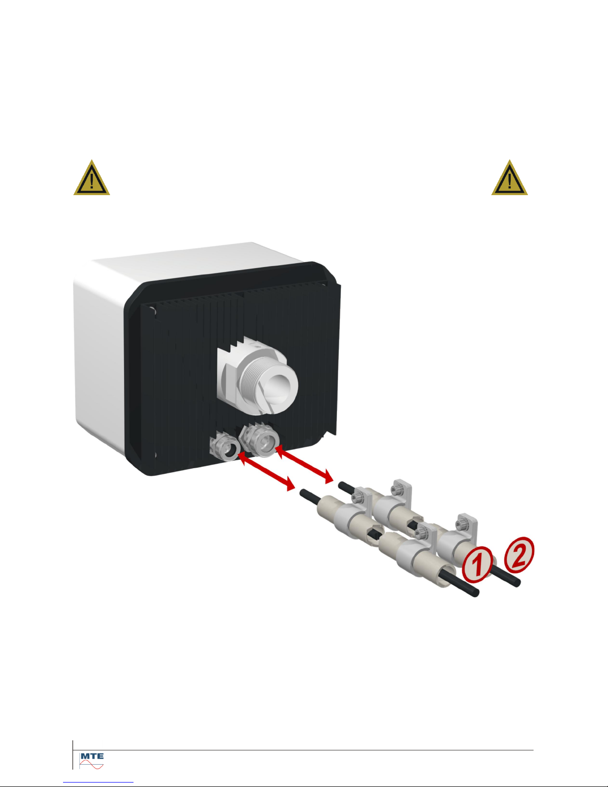
2.4.2. Electrical connection
Use protective conduits as protection for all cables and connect them to the corresponding
connectors inside of the unit (3.3). All cables have to be provided by the customer.
For feed through, following cable gland must be used for all cables:
1x M20 SKINTOP® cable gland (Clamping range 7,0 ... 13,0 mm)
1x M25 SKINTOP® cable gland (Clamping range 9,0 ... 17,0 mm)
Attention !!!
For cables with a smaller diameter please use reducing seal inserts to
provide clamping and sealing!
Note: The unit comes with 2 SKINTOP® cable glands (M20 and M25) from the factory!
Supply voltage connection:
Recommendation for supply voltage cable:
Cable type: PUR-PUR CEE JB 3x1.50 (or equivalent)
Cable diameter : 8,1 mm
Cross section : 1,5 mm2 (of 3 internal wires)
HYDROCAL 1001+ Installation and operation manual Page 15/76
Communication connection:
The Ethernet communication is either connected via copper wire (RJ45) or fibre optical (SC Du-
plex) (must be specified when ordering).
Copper wire:
Recommendation for Ethernet communication cable (copper):
Cable type: Ethernet cable Cat. 5e with RJ45 connector
Cable diameter : 6,3 mm
Fibre optical:
Recommendation for Ethernet communication cable (fibre optical):
Cable type: HITRONIC
®
HQN 1000 Multimode G4 62,5/125 with SC Duplex connector
Cable diameter : 6,5 mm
Bending radius: min. 15 x Ø
RS485 interface:
Recommendation for RS485 interface communication cable:
Cable type: UNITRONIC® BUS LD FD P cable 1x2x0.25 mm2, shielded, purple
Cable diameter : 6,2 mm
Alarm- and analog outputs:
Recommendation for alarm and analog outputs cable:
Cable type: ÖLFLEX® FD855CP (or equivalent)
Cable diameter : 13,3 mm
Cross section : 0,5 mm2 (of 16 internal wires)
2.4.3. Putting into operation
When the supply voltage for the unit is switched on, a short beep is hearable and after a short time
the LEDs of the internal and external user interface shows the specified conditions confirming that
the HYDROCAL unit is working correctly (4).
After successful initialization, you can remount the protection cover and fasten it with the
knurled thumb screw.
The measurement cycles are performed every 20 minutes and are synchronized on the clock
mark; this means the first measurement values are available approx. 2, 22 or 42 min. after the
clock mark.
To check the heating function, touch carefully the back plate after some minutes.
Attention, danger of burning!!!
Note: To check the correct regulation of the back plate heating use Hydrosoft - Online Sensors - and
check the back plate temperature T2.
HYDROCAL 1001+ Installation and operation manual Page 16/76
3. Hardware components
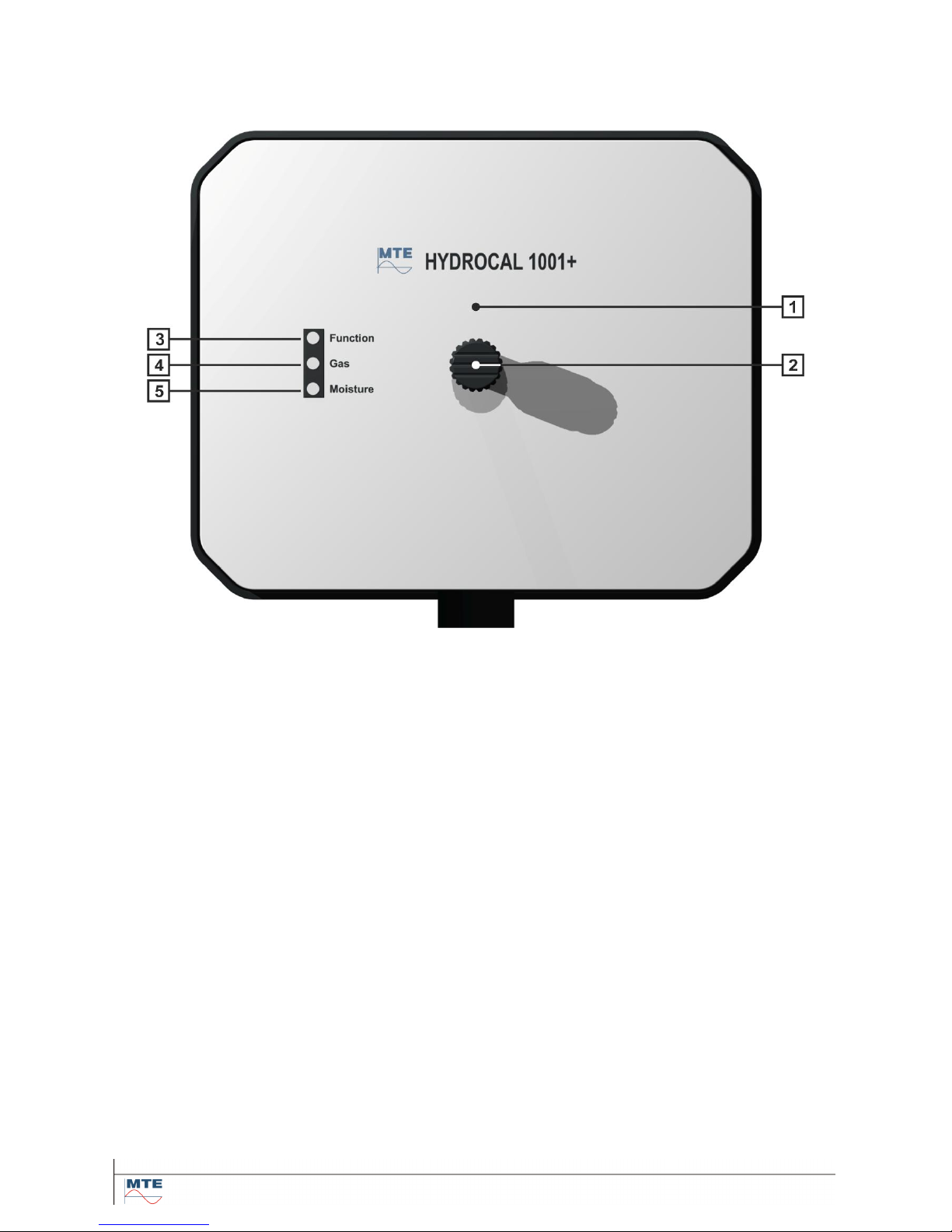
3.1. Front view
The front consists of the following components:
[1]
Protection cover with aeration hole
[2]
Knurled thumb screw to fasten the protection cover
[3]
Function LED of external user interface
[4]
Gas LED of external user interface
[5]
Moisture LED of external user interface
HYDROCAL 1001+ Installation and operation manual Page 17/76
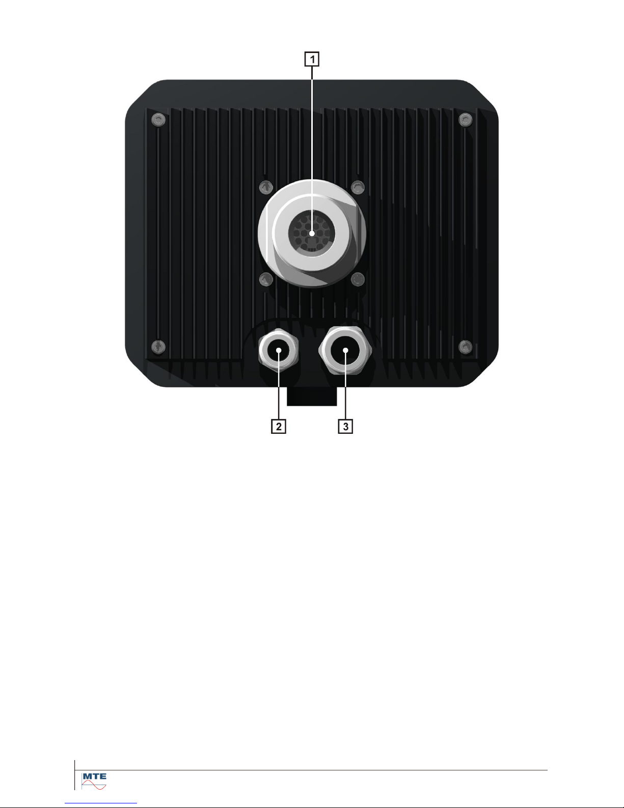
3.2. Rear view
[1]
Oil unit with connection thread
G 1½” DIN ISO 228-1
or
1½” NPT ANSI B 1.20.1
HYDROCAL 1001+ Installation and operation manual Page 18/76
[2]
Supply voltage connection with SKINTOP® cable gland M20
Nominal voltages: 120 V -20% +15% AC 50/60Hz 1) or
230 V -20% +15% AC 50/60Hz 1) or
120 V -20% +15% DC 1) or
230 V -20% +15% DC 1)
Other nominal voltages on request!
Power consumption: max. 250 VA
Micro-fuse at 120V: T3.15A
Micro-fuse at 230V: T2A
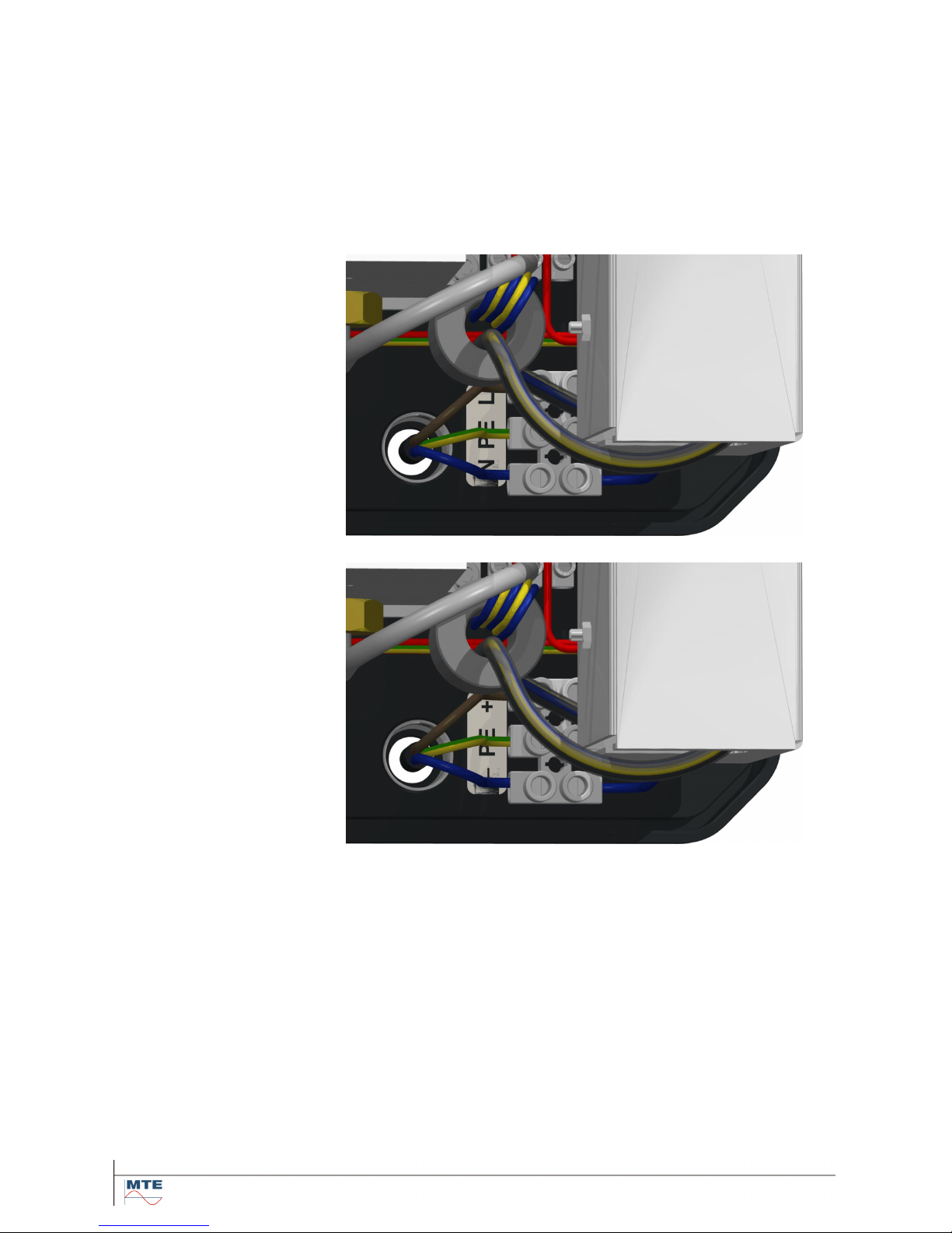
Connect the supply voltage cable as followed:
AC Version
Phase: L
Protection earth: PE
Neutral: N
DC Version
Plus conductor: +
Protection earth: PE
Minus conductor: –
Note 1):
120 V 120 V -20% = 96 V
min
120 V +15% = 138 V
max
230 V 230 V -20% = 184 V
min
230 V +15% = 264 V
max
[3]
System connection with SKINTOP® M25 cable gland
Communication (Ethernet / RS485) / Analog outputs / Relay outputs
HYDROCAL 1001+ Installation and operation manual Page 19/76
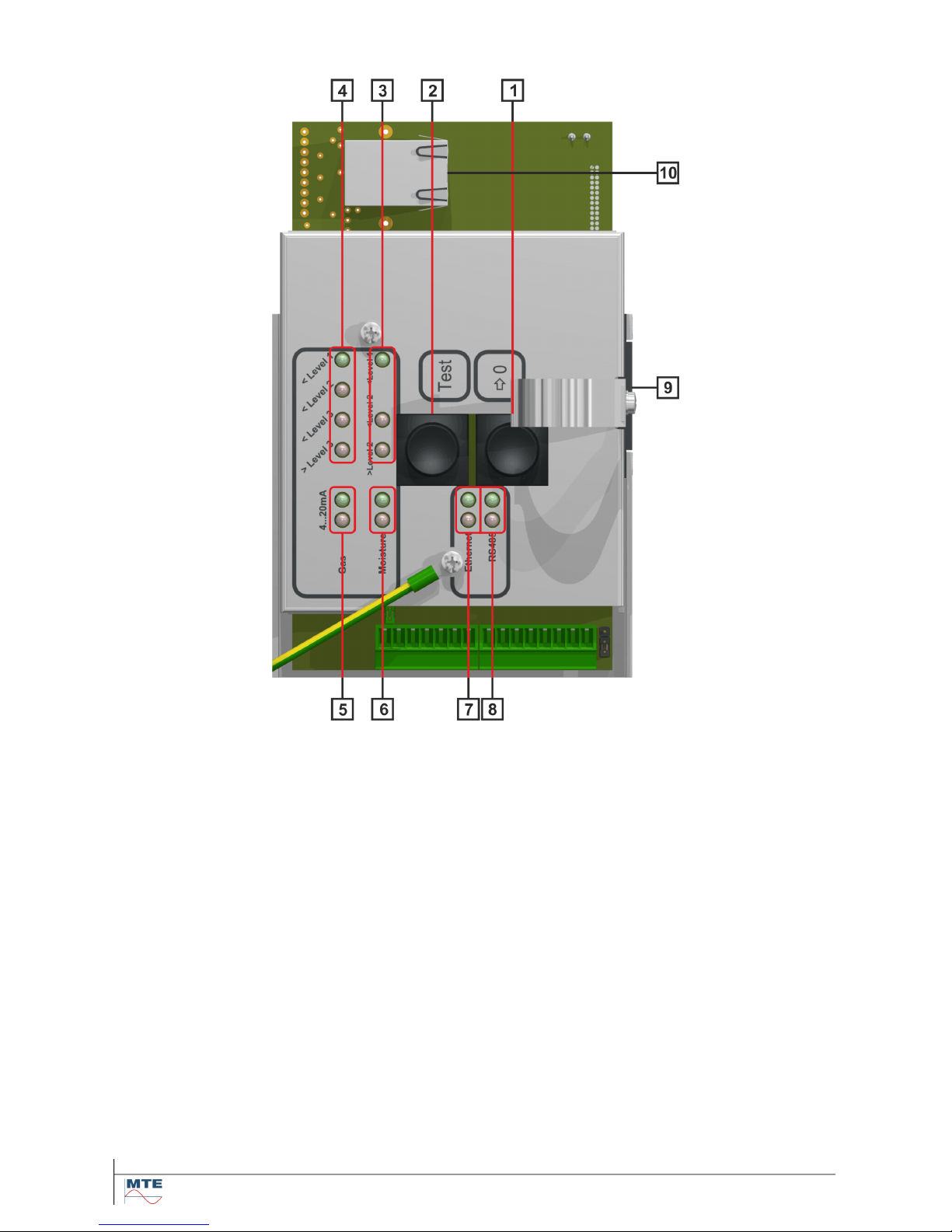
3.3. Connections of measurement- and controller card
[1]
Reset Button [→0] (to zero)
Functional test and alarm acknowledgment (automatic test of LEDs and digital outputs)
Communication interface reset – in conjunction with the test button
[2]
Test Button [Test]
Test mode (detailed manual test of analog- and digital outputs)
Communication interface reset – in conjunction with the reset button
[3]
LED bar level - Moisture
Moisture concentration indication with 3 single color LEDs
[4]
LED bar level - Gas
Gas concentration indication with 4 single color LEDs
[5]
Analog output LEDs - Gas concentration
Analog output indication for gas concentration with 2 single color LEDs
[6]
Analog output LEDs - Moisture concentration
Analog output indication for moisture concentration with 2 single color LEDs
[7]
Ethernet connection LEDs
Status and data traffic indication with 2 single color LEDs
[8]
RS485 connection LEDs
Status and data traffic indication with 2 single color LEDs
HYDROCAL 1001+ Installation and operation manual Page 20/76
[9]
Function, Gas & Moisture LEDs
of external user interface with 3 multicolor LEDs
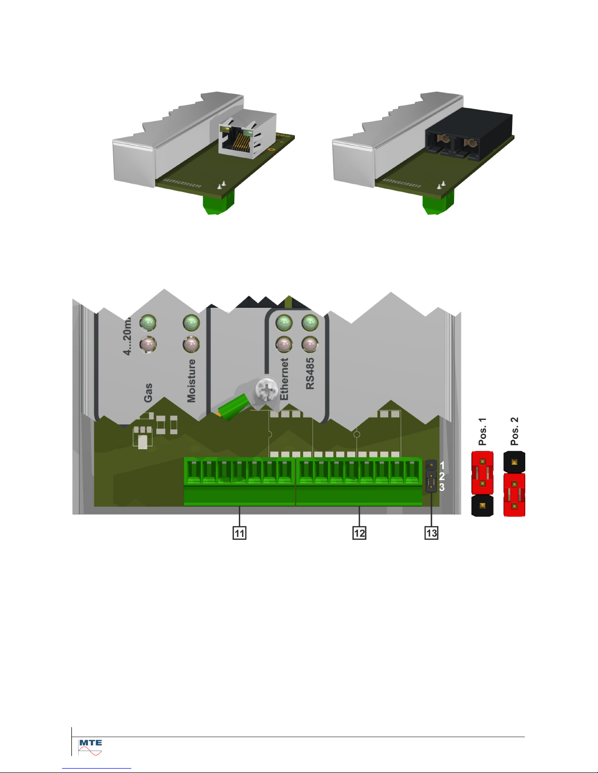
[10]
Connection ETHERNET communication
Communication connection via Ethernet
Copper wired
(RJ45)
or
Fibre optic
(SC-Duplex)
The connection sockets are mounted directly on the measurement- and controller card
(must be specified when ordering).
[13]
Jumper J1 – Function relay contact (when system is okay, relay is switched on )
The function relay output can operate as a closing or opening contact. The configuration is
selected by the jumper J1, which is located near the connection terminal X2:8:
J1:1-2 Pos. 1 Contact is open, when relay is switched on (Normally Closed)
J1:2-3 Pos. 2 Contact is closed, when relay is switched on (Normally Open)
HYDROCAL 1001+ Installation and operation manual Page 21/76
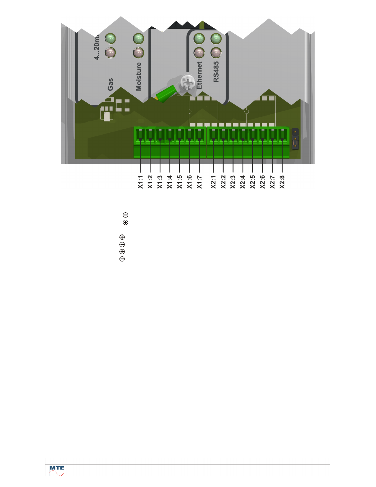
[11]
Connection terminal X1: RS485 / analog outputs
Connection for RS485 interface / analog outputs DC (0/4…. 20 mA DC)
X1:1 OUTA RS485 interface
X1:2 OUTB RS485 interface
X1:3 GNDio RS485 interface
X1:4 AO1 Analog output 1 – Gas concentration
X1:5 AO1 Analog output 1 – GNDio
X1:6 AO2 Analog output 2 – Moisture concentration
X1:7 AO2 Analog output 2 – GNDio
Note: Free assignment for both analog outputs.
[12]
Connection terminal X2: Relay outputs
Connection for relay outputs (220 VDC/VAC / 2 A / 60 W)
X2:1 DOR1 Relay output 1 – Gas high alarm
X2:2 DOR1 Relay output 1 – Gas high alarm
X2:3 DOR2 Relay output 2 – Gas high-high alarm
X2:4 DOR2 Relay output 2 – Gas high-high alarm
X2:5 DOR3 Relay output 3 – Moisture alarm
X2:6 DOR3 Relay output 3 – Moisture alarm
X2:7 DOR4 Relay output 4 – Function alarm
X2:8 DOR4 Relay output 4 – Function alarm
HYDROCAL 1001+ Installation and operation manual Page 22/76
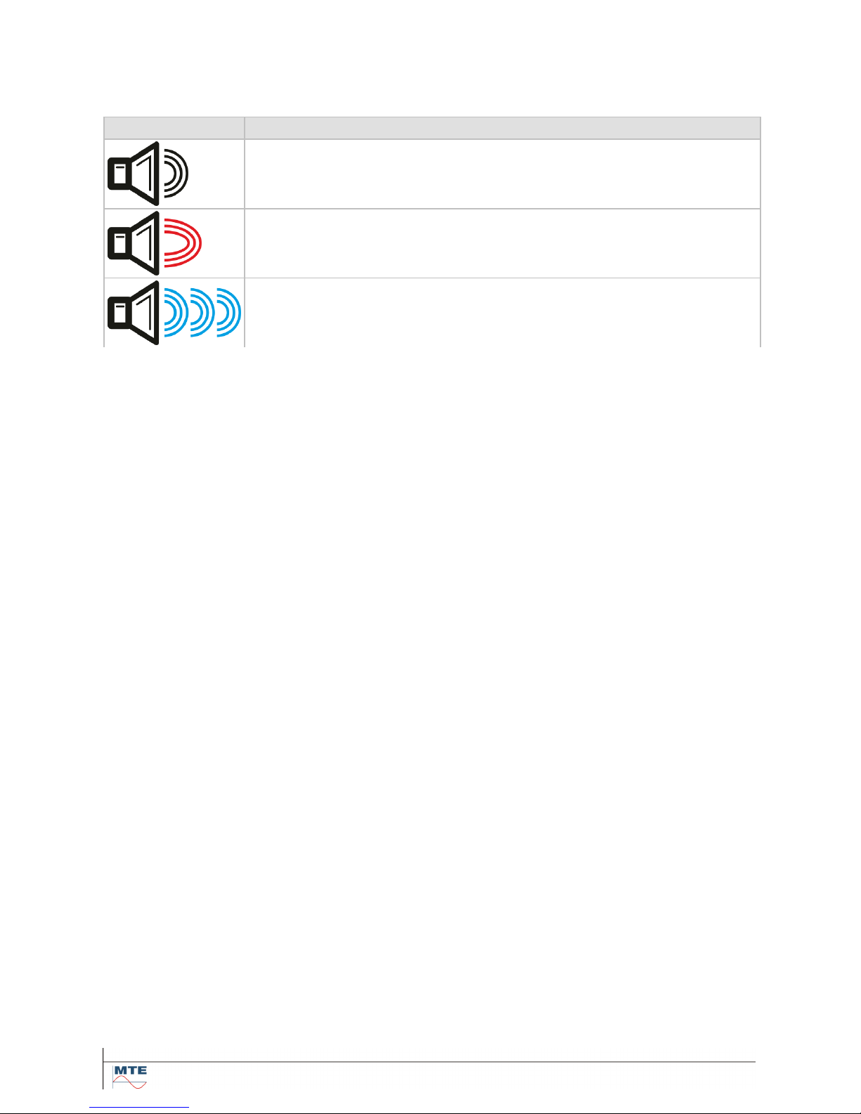
3.3.1. Beeper
The measurement- and controller card contains a beeper for additional acoustic signalization. The
beeper has three different beep sounds which vary in lengths and sound form:
Icon
Description
Short constant beep
Long constant beep with a slightly higher tone pitch
Long oscillating beep (whistle sound)
 Loading...