

Page 1
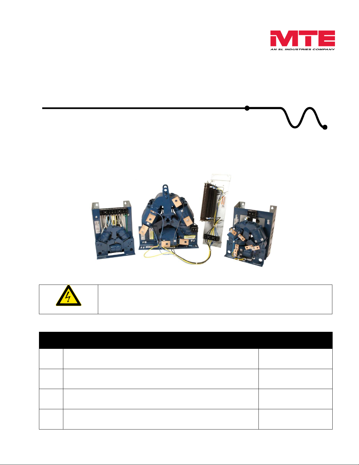
WARNING
High Voltage! Only a qualified electrician can carry out the electrical
installation of this filter.
Quick Reference
❶
Selection Guide
Pages 7 – 16
❷
Installation Guide
Pages 17 – 22
❸
Startup/Troubleshooting
Pages 23 – 25
❹
Reference Drawings
Pages 28 – 100
dV Sentry™
380V – 600V
TECHNICAL REFERENCE MANUAL
FORM: DVS-TRM-E
REL. September 2014
REV. 001
© 2014 MTE Corporation
Page 2

dV Sentry Technical Reference Manual 380V – 600V
TABLE OF CONTENTS
1. WARNINGS ................................................................................................................................. 3
WARNINGS AND CAUTIONS ............................................................................................................. 3
PRODUCT SAFETY LABELING .......................................................................................................... 4
GENERAL SAFETY INSTRUCTIONS ................................................................................................... 4
2. INTRODUCTION .......................................................................................................................... 6
RECEIPT & REPAIR STATEMENT ...................................................................................................... 6
3. HOW TO SELECT ....................................................................................................................... 7
SELECTION GUIDE ......................................................................................................................... 7
MODEL NUMBER CODE SYSTEM: .................................................................................................... 8
PART NUMBER SELECTION TABLES ................................................................................................. 9
4. PRODUCT SPECIFICATIONS ................................................................................................... 12
PERFORMANCE SPECIFICATIONS .................................................................................................. 12
ENCLOSURES .............................................................................................................................. 13
AGENCY APPROVALS ................................................................................................................... 13
WARRANTY ................................................................................................................................. 13
5. DV/DT FILTER PERFORMANCE .............................................................................................. 14
FILTER EFFICIENCY + WATT LOSS ................................................................................................. 15
ALTITUDE DERATING .................................................................................................................... 16
MOTOR FREQUENCY DERATING .................................................................................................... 16
6. HOW TO INSTALL .................................................................................................................... 17
INSTALLATION CHECKLIST ............................................................................................................ 17
G
ROUNDING
BASIC SCHEMATIC DIAGRAM ......................................................................................................... 19
INTERCONNECTION DIAGRAM – PANEL (3A-110A) AND ENCLOSED (3A-600A) ................................ 20
INTERCONNECTION DIAGRAM – MODULAR (130A-600A) ................................................................ 21
TORQUE RATINGS ........................................................................................................................ 22
7. START UP ................................................................................................................................. 23
STARTUP CHECKLIST ................................................................................................................... 23
8. TROUBLESHOOTING ............................................................................................................... 25
APPENDIX .................................................................................................................................... 27
............................................................................................................................... 18
Form: DVS-TRM-E September 2014 REV. 001 1
Page 3

dV Sentry Technical Reference Manual 380V – 600V
List of Figures
Figure 6-1: Basic Schematic Diagram ..................................................................................... 19
Figure 6-2: Open Panel and Enclosed Diagram ...................................................................... 20
Figure 6-3: Modular Diagram .................................................................................................. 21
List of Tables
Table 3-1: Panel Selection Table .............................................................................................. 9
Table 3-2: Enclosed NEMA 1/2 Selection Table ...................................................................... 10
Table 3-3: Enclosed NEMA 3R Selection Table ...................................................................... 11
Table 4-1: Performance Specifications .................................................................................... 12
Table 5-1: Performance Chart ................................................................................................. 14
Table 5-2: Filter Efficiency & Watt Loss ................................................................................... 15
Table 5-3: Altitude Derating Curve ......................................................................................... 16
Table 5-4: Current Derating for Drive Output Frequency ........................................................ 16
Table 6-1: Torque Ratings ....................................................................................................... 22
Table 8-1: Troubleshooting Guide ........................................................................................... 25
Form: DVS-TRM-E September 2014 REV. 001 2
Page 4
dV Sentry Technical Reference Manual 380V – 600V
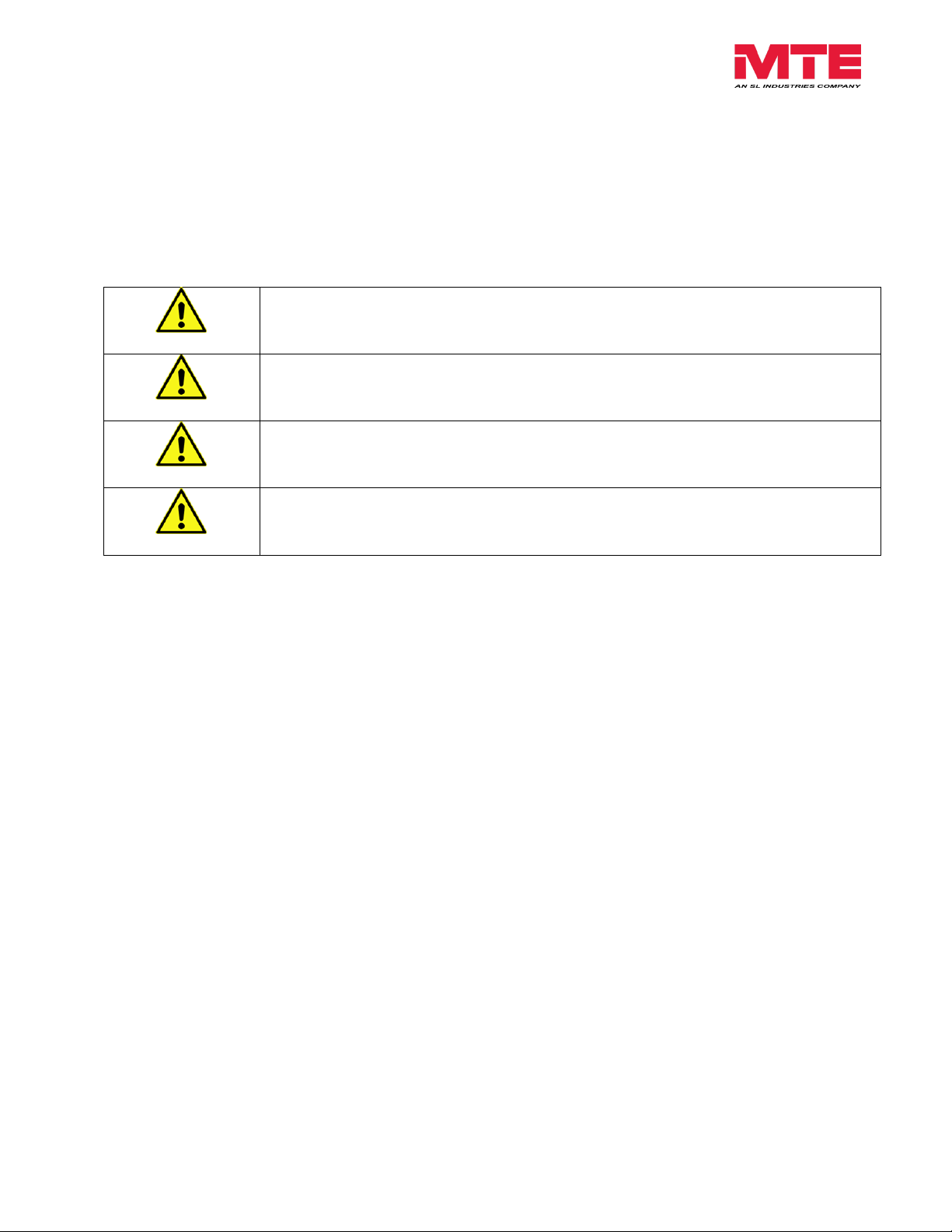
WARNING
WARNING describes situations that can lead to serious faults,
physical injuries, or even death.
Caution
Caution describes situations that can lead to malfunction or
possible equipment damage.
WARNING
High Voltage Warning: warns of situations that dangerously
high voltage is involved. Failure to use proper precautions may
lead to serious injury or even death.
WARNING
General Warning: warns of situations that can result in serious
injury or death if proper precautions are not used.
Caution
General Caution: identifies situations that could lead to
malfunction or possible equipment damage.
1. WARNINGS
Warnings and Cautions
There are two types of warnings in this manual:
The following symbols are used in this manual.
Form: DVS-TRM-E September 2014 REV. 001 3
Page 5
dV Sentry Technical Reference Manual 380V – 600V
WARNING
High Voltage! Only a qualified electrician can carry out the electrical
installation of this filter.
WARNING
High voltage is used in the operation of this filter. Use Extreme caution to
avoid contact with high voltage when operating, installing or repairing this
filter.
Injury or death may result if safety precautions are not
observed.
WARNING
The opening of the branch circuit protective device may be an indication that a
fault current has been interrupted. To reduce the risk of fire or electrical shock,
current-carrying parts and other components of the filter should be examined and
replaced if damaged.
WARNING
An upstream disconnect/protection device must be used as required by the
National Electrical Code (NEC) or governing authority.
WARNING
Even if the upstream disconnect/protection device is open, the drive down stream
of the filter may feedback high voltage to the filter. The drive safety instructions
must be followed. Injury or death may result if safety precautions are not
observed.
WARNING
The filter must be grounded with a grounding conductor connected to all grounding
terminals. Modular filters must have reactor grounded through a 2”x2” area
cleaned of paint and varnish on lower mounting bracket.
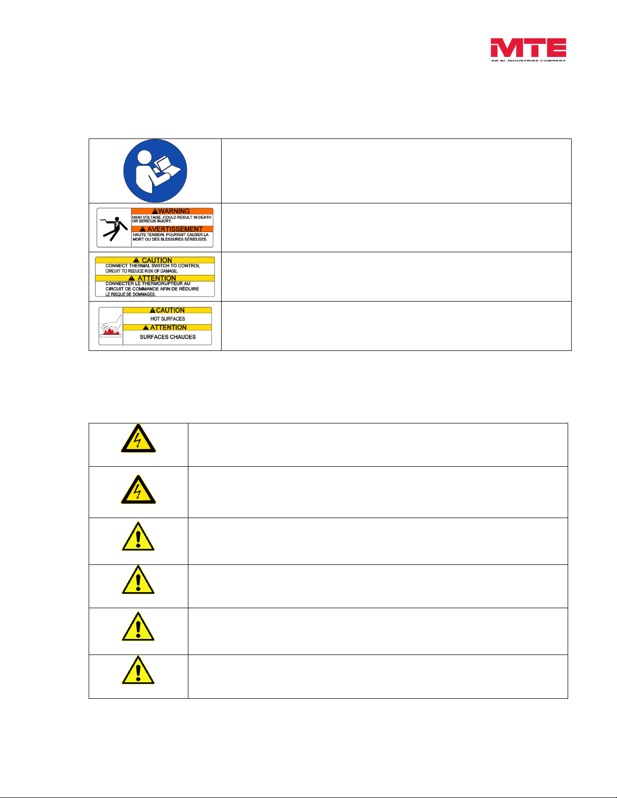
Label notes to installer to refer to instruction manual first before
installing.
High Voltage: surfaces on product can have high voltage which can
cause injury.
Connect Thermal Switch: connecting the thermal switch can reduce
risk of damage.
Hot Surfaces: surfaces of product can be hot at times and cause
burns.
Product Safety Labeling
The following labels are placed on the DVS product:
General Safety Instructions
Form: DVS-TRM-E September 2014 REV. 001 4
Page 6
dV Sentry Technical Reference Manual 380V – 600V
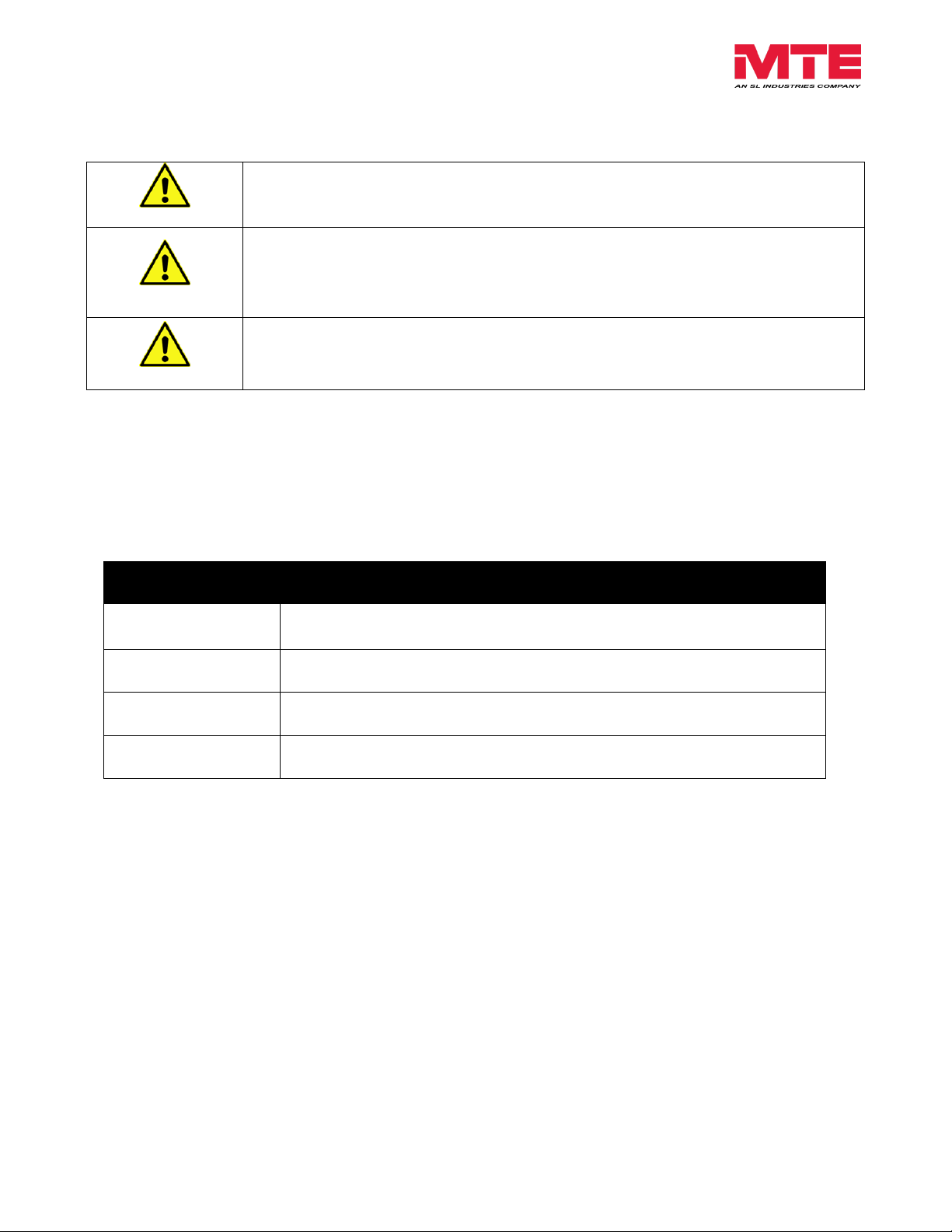
WARNING
Only spare parts obtained from MTE Corporation or an authorized MTE distributor
can be used.
Caution
Loose or improperly secured connections may damage or degrade filter
performance. Visually inspect and secure all electrical connections before
power is applied to the filter.
Caution
Wiring should not be routed underneath panel in resistor housing. Doing so could
result in fire or damage to the product.
Caution
Product should not be mounted on wood or any other combustible surface. Doing
so could lead to fire or damage to the product.
Form: DVS-TRM-E September 2014 REV. 001 5
Page 7

dV Sentry Technical Reference Manual 380V – 600V
2. INTRODUCTION
The purpose of the manual is to properly specify, size, install, interconnect and operate the
dV/dt filter.
For most current information, please refer to website
http://www.mtecorp.com/products/dvsentry/
This manual is intended for use by personnel experienced in the operation and maintenance of
inverters. Because of the high voltages required by the filter, inverter and the potential dangers
presented by rotating machinery, it is essential that all personnel involved in the operation and
maintenance of this filter know and practice the necessary safety precautions for this type of
equipment. Personnel should read and understand the instructions contained in this manual
before installing, operating or servicing the filter and inverter to which it is connected.
Receipt & Repair Statement
Upon Receipt of this Filter:
The dV/dt filter has been subjected to demanding factory tests before shipment. Carefully
inspect the shipping container for damage that may have occurred in transit. Then unpack the
filter and carefully inspect for any signs of damage. Save the shipping container for future
transport of the filter.
In the event of damage, please contact and file a claim with the freight carrier involved
immediately.
If the equipment is not going to be put into service upon receipt, cover and store the filter in a
clean, dry location. After storage, ensure that the equipment is dry and that no condensation or
dirt has accumulated on the internal components of the filter before applying power.
Repair/Exchange Procedure:
MTE Corporation requires a Return Material Authorization Number and form before we can
accept any filters that qualify for return or repair. If problems or questions arise during
installation, setup, or operation of the filter, please contact MTE for assistance at:
Toll Free: 1-800-455-4MTE (1-800-455-4683)
International Tel: 262-253-8200
Fax: 262-253-8222
Form: DVS-TRM-E September 2014 REV. 001 6
Page 8

dV Sentry Technical Reference Manual 380V – 600V
3. HOW TO SELECT
Selection Guide
The dV Sentry Motor Protection Filter is intended for use on inverter duty motors. It will
typically be used with lead lengths up to 1,000 feet. The dV Sentry Motor Protection Filter will
provide both common mode and differential mode reduction to prevent overvoltage that can
occur due to reflected wave phenomena. The differential mode filtering reduces EMI,
increases motor life, and reduce cables voltage stress. The added common mode protection
will reduce bearing failures, degradation of cable insulation to ground, and further reduce EMI.
The suitability of this filter for a specific application must therefore be determined by the
customer. In no event will MTE Corporation assume responsibility or liability for any direct or
consequential damages resulting from the use or application of this filter. Nor will MTE
Corporation assume patent liability with respect to the use of information, circuits or equipment
described in this instruction manual.
*For non-inverter duty motors, please refer to the SineWave Guardian filter.
dV Sentry Motor Protection Filters are available in Panel, NEMA 1/2, and 3R mechanical
configurations.
Please verify information below for proper selection:
Lead Length: This product is suitable for applications with motor leads up to 1,000 ft.
Contact MTE Application Engineering for possible longer applications.
Voltage: Input voltage from 380V – 600V. See Table 4-1 (p13) for specification.
Current Rating: Support for 3 Amps – 600 Amps.
Switching Frequency: Support for carrier frequency of 2kHz – 10kHz see Table 4-1
(p13).
Drive Output Frequency: Support for 0Hz to 90Hz without derating, >90Hz to 120Hz
with derating. See (p17) for derating curve.
Temperature: Maximum ambient temperature, 60C (open), 50C (enclosed). See
Table 4-1 (p13) for specification.
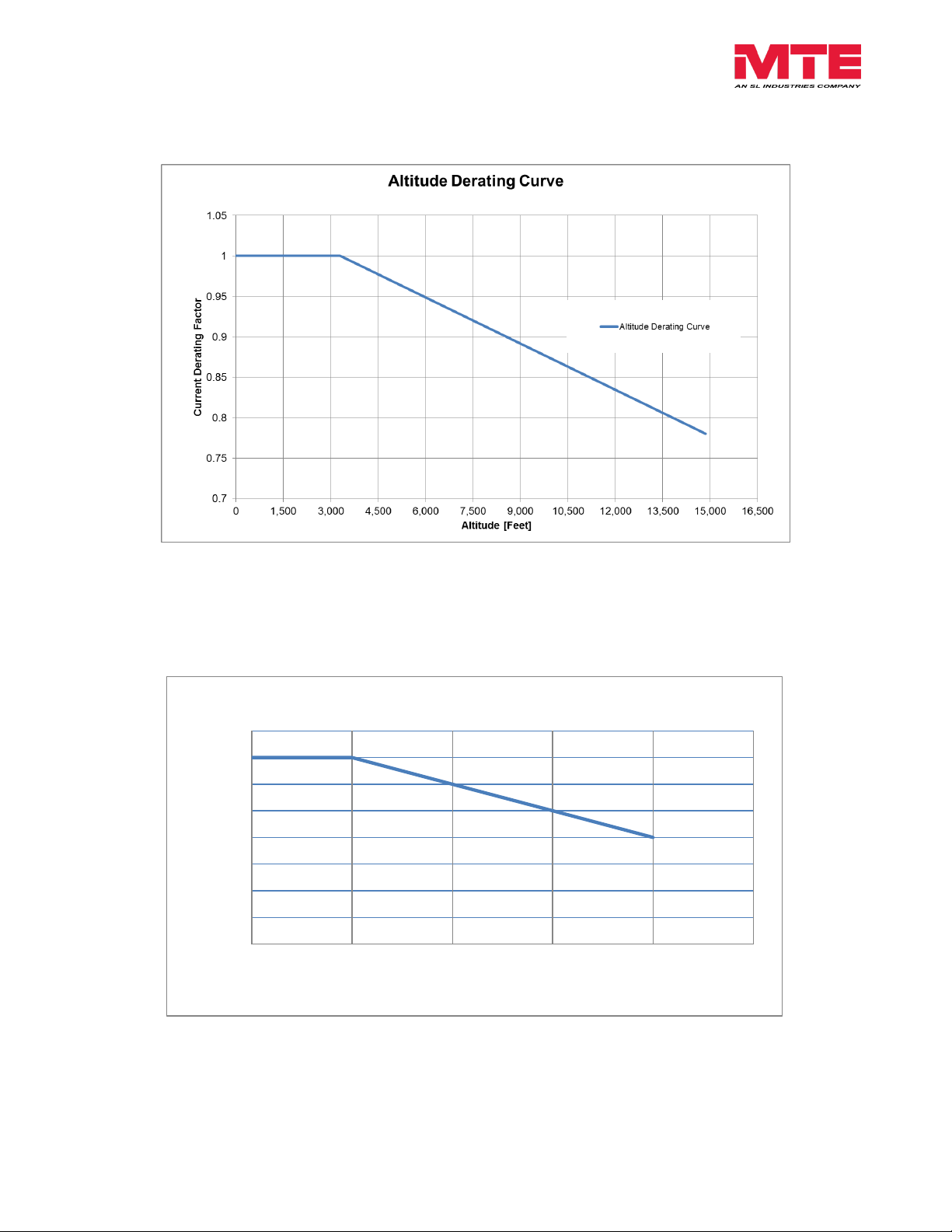
Altitude: 3,300 feet above sea level without derating. See
(p17) for derating curve.
Enclosure Type: Panel, NEMA 1/2 & NEMA 3R, see (p14) for enclosure descriptions.
Motor Insulation Class: Verify motor meets inverter duty standards per NEMA MG1
Section 31.
*Filters cannot be paralleled for higher current ratings.
Form: DVS-TRM-E September 2014 REV. 001 7
Page 9

dV Sentry Technical Reference Manual 380V – 600V
Model Number Code System:
DVS X _ _ _ _ E
dV Sentry Filter
Type
P = Panel
G = General Purpose (NEMA 1/2)
W = Weather (NEMA 3R)
Current Rating
(i.e. 0045 is 45 Amps)
Voltage Rating
(380V – 600V)
Form: DVS-TRM-E September 2014 REV. 001 8
Page 10
dV Sentry Technical Reference Manual 380V – 600V
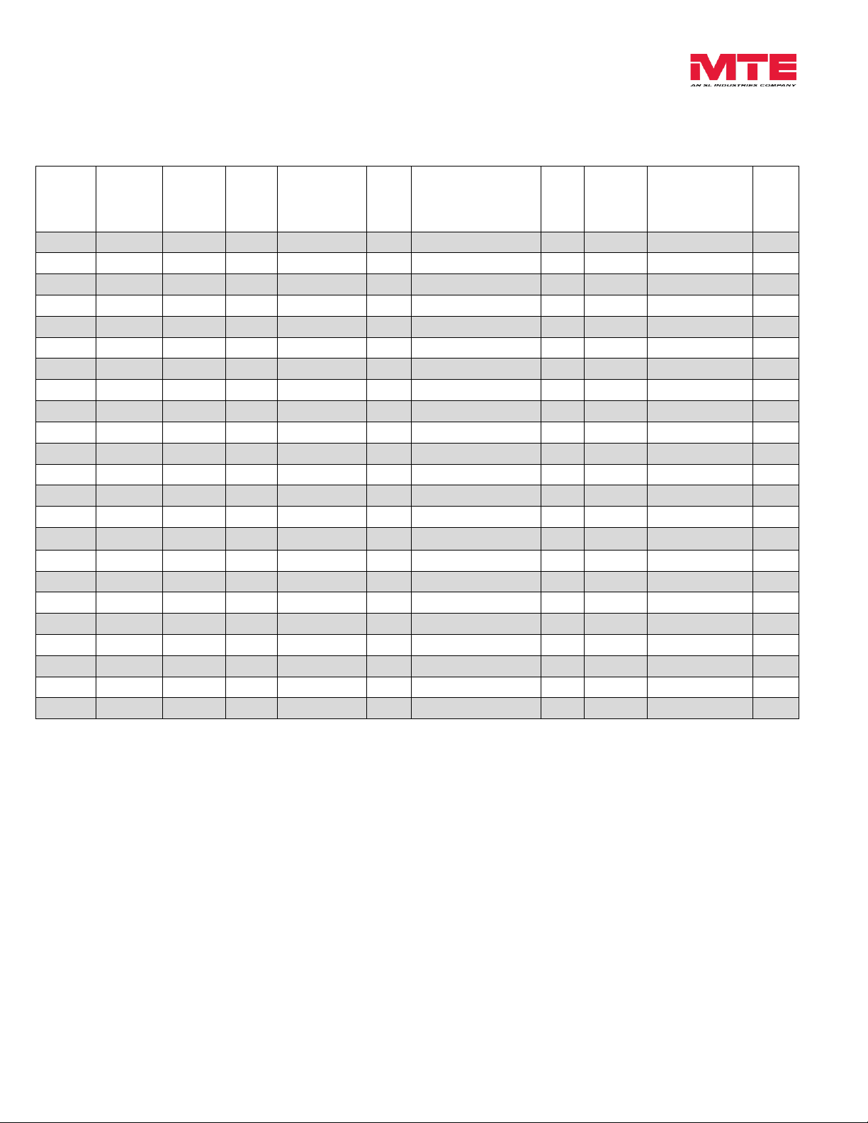
380V
Motor
KW
480V
Motor
HP
550V-
600V
Motor
HP
Filter
Amp
Rating
Part
Number
App.
Wt.
(lbs.)
Open Magnetics
(in.)
(H x W x D)
Ref.
Fig.
Watts*
Loss
Resistor Panel
(in.)
(H x W x D)
Ref.
Fig.
0.5- 1.1
0.5-1.5
0.5 - 2
3
DVSP0003E
7
9.1 x 6.7 x 7.7
A-1
227
-
-
1.5 2 3
4
DVSP0004E
7
9.1 x 6.7 x 7.7
A-2
227
-
-
2.2 - 3 3 5
5
DVSP0007E
7
9.1 x 6.7 x 7.7
A-3
227
-
- 4 5
7.5
9
DVSP0009E
7
9.1 x 6.7 x 7.7
A-4
227
-
-
5.5
7.5
10
12
DVSP0012E
7
9.1 x 6.7 x 7.7
A-5
227
-
-
7.5
10
15
17
DVSP0017E
8
9.1 x 6.7 x 7.5
A-6
334
-
-
11
15
20
22
DVSP0022E
11
9.1 x 6.7 x 8.2
A-7
278
-
- - 20
25
27
DVSP0027E
11
9.1 x 6.7 x 8.2
A-8
267
-
-
15
25
30
35
DVSP0035E
15
12.0 x 9.0 x 7.9
A-9
260
-
-
18.5-22
30
40
45
DVSP0045E
15
12.0 x 9.0 x 7.9
A-10
219
-
- - 40
50
45
DVSP0055E
22
12.0 x 9.0 x 8.2
A-11
297
-
-
30
50
60
65
DVSP0065E
31
12.0 x 9.0 x 11.0
A-12
376
-
-
37
60
75
80
DVSP0080E
30
12.0 x 9.0 x 11.0
A-13
336
-
-
45 - 55
75
100
110
DVSP0110E
32
12.0 x 9.0 x 11.0
A-14
363
-
-
-
100
125
130
DVSP0130E
51
13.5 x 13.6 x 7.9
A-15
393
18.4 x 5.0 x 7.0
A-70
75 - 90
125
150
160
DVSP0160E
69
13.5 x 13.6 x 9.0
A-16
412
18.4 x 5.0 x 7.0
A-70
110
150
200
200
DVSP0200E
69
13.5 x 13.6 x 9.0
A-17
449
18.4 x 5.0 x 7.0
A-70
132
200
250
250
DVSP0250E
89
15.0 x 15.1 x 10.3
A-18
550
18.4 x 5.0 x 7.0
A-71
160
250
300
305
DVSP0305E
94
15.2 x 15.1 x 10.4
A-19
616
18.4 x 5.0 x 7.0
A-71
185-200
300
350
365
DVSP0365E
124
15.1 x 15.1 x 11.8
A-20
703
18.4 x 5.0 x 7.0
A-71 - 350
450
415
DVSP0415E
124
15.1 x 15.1 x 11.8
A-21
703
18.4 x 5.0 x 7.0
A-71
250
400–450
500 - 550
515
DVSP0515E
157
14.9 x 15.1 x 13.3
A-22
1027
18.4 x 5.0 x 7.0
A-72
315
500
600
600
DVSP0600E
164
15.1 x 15.1 x 13.4
A-23
1062
18.4 x 5.0 x 7.0
A-72
Part Number Selection Tables
Table 3-1: Panel Selection Table
*Based on a typical 480V, 60Hz output frequency, 1,000 feet of drive cable, 2kHz carrier
frequency at full load application.
Form: DVS-TRM-E September 2014 REV. 001 9
Page 11
dV Sentry Technical Reference Manual 380V – 600V
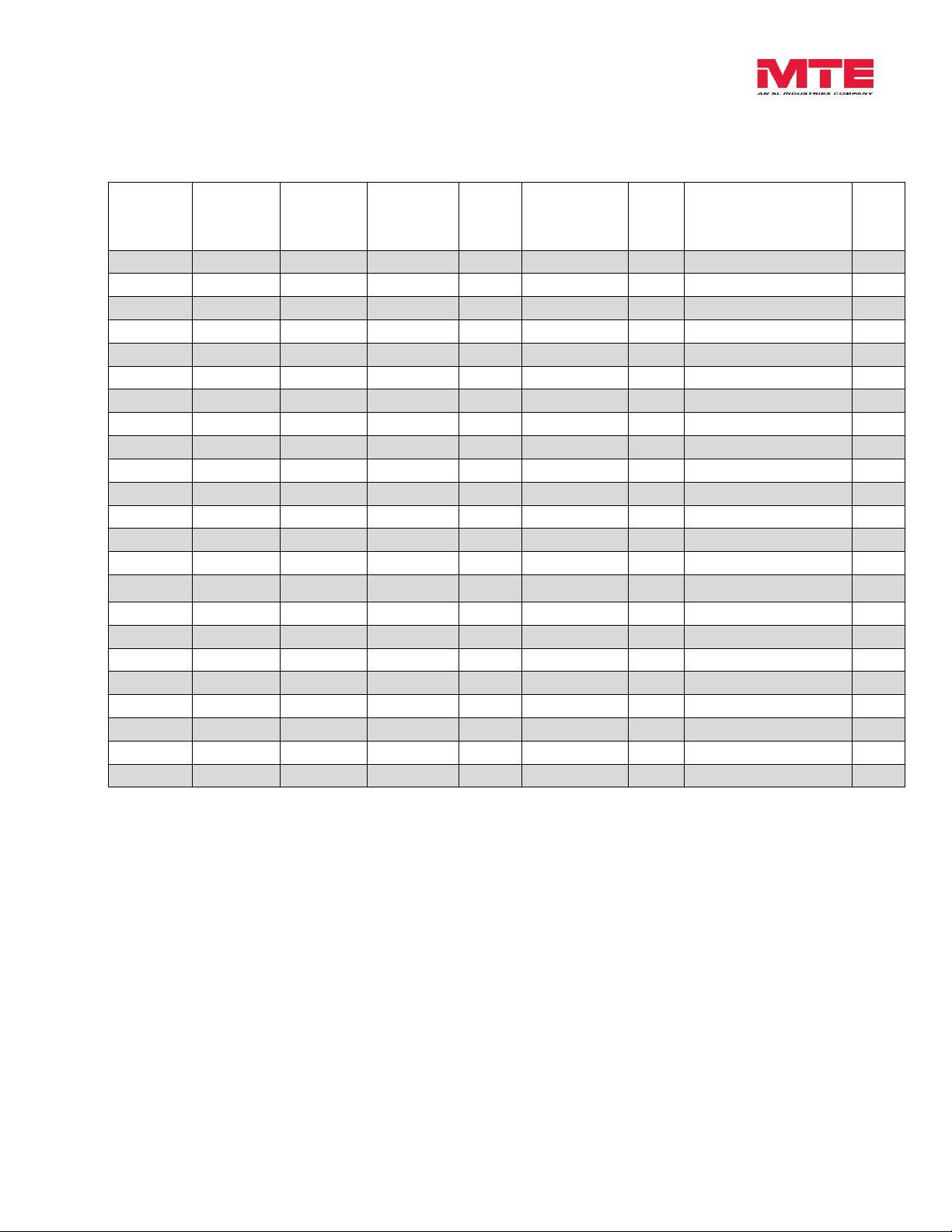
380V
Motor
KW
380V
Motor
HP
480V
Motor
HP
550V- 600V
Motor
HP
Filter
Amp
Rating
Part
Number
App.
Wt.
(lbs.)
NEMA 1/2 Enclosure
(in.)
(H x W x D)
Ref.
Fig.
0.5 – 1.1
0.5 – 1.5
0.5 – 1.5
0.5 - 2
3
DVSG0003E
18
13.2 x 13.0 x 13.0
A-24
1.5 2 2 3 4
DVSG0004E
18
13.2 x 13.0 x 13.0
A-25
2.2 - 3 3 3 5 5
DVSG0007E
18
13.2 x 13.0 x 13.0
A-26
4
5.5 5 7.5
9
DVSG0009E
18
13.2 x 13.0 x 13.0
A-27
5.5
7.5
7.5
10
12
DVSG0012E
18
13.2 x 13.0 x 13.0
A-28
7.5
10
10
15
17
DVSG0017E
19
13.2 x 13.0 x 13.0
A-29
11
15
15
20
22
DVSG0022E
22
13.2 x 13.0 x 13.0
A-30
- - 20
25
27
DVSG0027E
22
13.2 x 13.0 x 13.0
A-31
15
20
25
30
35
DVSG0035E
24
13.2 x 13.0 x 13.0
A-32
18.5 - 22
25 – 30
30
40
45
DVSG0045E
24
13.2 x 13.0 x 13.0
A-33
- - 40
50
45
DVSG0055E
32
13.2 x 13.0 x 13.0
A-34
30
40
50
60
65
DVSG0065E
40
13.2 x 13.0 x 13.0
A-35
37
50
60
75
80
DVSG0080E
40
13.2 x 13.0 x 13.0
A-36
45 - 55
60 – 75
75
100
110
DVSG0110E
43
13.2 x 13.0 x 13.0
A-37
- - 100
125
130
DVSG0130E
93
24.0 x 17.1 x 17.1
A-38
75 - 90
100 – 120
125
150
160
DVSG0160E
111
24.0 x 17.1 x 17.1
A-39
110
150
150
200
200
DVSG0200E
111
24.0 x 17.1 x 17.1
A-40
132
175
200
250
250
DVSG0250E
127
33.9 x 18.3 x 20.9
A-41
160
220
250
300
305
DVSG0305E
165
33.9 x 18.3 x 20.9
A-42
185 - 200
250 – 270
300
350
365
DVSG0365E
195
33.9 x 18.3 x 20.9
A-43
- - 350
450
415
DVSG0415E
195
33.9 x 18.3 x 20.9
A-44
250
340
400 – 450
500 - 550
515
DVSG0515E
317
51.3 x 27.7 x 24.9
A-45
315
430
500
600
600
DVSG0600E
325
51.3 x 27.7 x 24.9
A-46
Part Number Selection Tables
Table 3-2: Enclosed NEMA 1/2 Selection Table
Form: DVS-TRM-E September 2014 REV. 001 10
Page 12

dV Sentry Technical Reference Manual 380V – 600V
380V
Motor
KW
380V
Motor
HP
480V
Motor
HP
550V- 600V
Motor
HP
Filter
Amp
Rating
Part
Number
App.
Wt.
(lbs.)
NEMA 3R Enclosure
(in.)
(H x W x D)
Ref.
Fig.
0.5 – 1.1
0.5 – 1.5
0.5 – 1.5
0.5 - 2
3
DVSW0003E
24
15.5 x 10.9 x 12.0
A-47
1.5 2 2 3 4
DVSW0004E
24
15.5 x 10.9 x 12.0
A-48
2.2 - 3 3 3 5 5
DVSW0007E
24
15.5 x 10.9 x 12.0
A-49 4 5.5 5 7.5
9
DVSW0009E
24
15.5 x 10.9 x 12.0
A-50
5.5
7.5
7.5
10
12
DVSW0012E
24
15.5 x 10.9 x 12.0
A-51
7.5
10
10
15
17
DVSW0017E
25
15.5 x 10.9 x 12.0
A-52
11
15
15
20
22
DVSW0022E
28
15.5 x 10.9 x 12.0
A-53
- - 20
25
27
DVSW0027E
28
15.5 x 10.9 x 12.0
A-54
15
20
25
30
35
DVSW0035E
30
15.5 x 10.9 x 12.0
A-55
18.5 - 22
25 – 30
30
40
45
DVSW0045E
30
15.5 x 10.9 x 12.0
A-56
- - 40
50
45
DVSW0055E
75
24.0 x 12.5 x 22.9
A-57
30
40
50
60
65
DVSW0065E
84
24.0 x 12.5 x 22.9
A-58
37
50
60
75
80
DVSW0080E
84
24.0 x 12.5 x 22.9
A-59
45 - 55
60 – 75
75
100
110
DVSW0110E
85
24.0 x 12.5 x 22.9
A-60 - -
100
125
130
DVSW0130E
133
33.9 x 18.3 x 26.0
A-61
75 - 90
100 – 120
125
150
160
DVSW0160E
151
33.9 x 18.3 x 26.0
A-62
110
150
150
200
200
DVSW0200E
151
33.9 x 18.3 x 26.0
A-63
132
175
200
250
250
DVSW0250E
167
33.9 x 18.3 x 26.0
A-64
160
220
250
300
305
DVSW0305E
172
33.9 x 18.3 x 26.0
A-65
185 - 200
250 – 270
300
350
365
DVSW0365E
202
33.9 x 18.3 x 26.0
A-66
- - 350
450
415
DVSW0415E
202
33.9 x 18.3 x 26.0
A-67
250
340
400 – 450
500 - 550
515
DVSW0515E
330
51.3 x 27.7 x 30.0
A-68
315
430
500
600
600
DVSW0600E
338
51.3 x 27.7 x 30.0
A-69
Part Number Selection Tables
Table 3-3: Enclosed NEMA 3R Selection Table
Form: DVS-TRM-E September 2014 REV. 001 11
Page 13

dV Sentry Technical Reference Manual 380V – 600V
Service Load Condition
Invertor Duty Three Phase Motors
Voltage
380 – 600 VAC +/- 10%, 60Hz
Input Voltage Wave Form
PWM
Inverter Switching Frequency
2kHz – 10kHz (3-110A models)
2kHz – 5kHz (130A-600A models)
Inverter Operating Frequency
0 – 90 Hz without derating
Maximum Ambient
Temperature
60C Open filters
50C Enclosed Filter
Insertion Loss (Voltage)
1.7% at 60 Hz, 2.6% at 90 Hz
Efficiency
>98%
Current range
3A – 600A
Available form factors
Panel
NEMA 1/2
NEMA 3R
Altitude without derating
1,000 feet above sea level
Maximum Motor Lead Length
1,000 feet
Relative Humidity
0% to 99% non-condensing
Current Rating
100% RMS Continuous
150% for 1 minute
200% for 10 sec
*Operating in overload will result in increased proportional voltage drop
Audible Noise
<65db at 1 meter
Rise Time
Less than 0.1 uS
Peak Voltage
150% of DC bus voltage up to 1,000 feet
Common Mode Reduction
50%+ Peak Current Reduction Typical
4. PRODUCT SPECIFICATIONS
Performance Specifications
Table 4-1: Performance Specifications
Form: DVS-TRM-E September 2014 REV. 001 12
Page 14

dV Sentry Technical Reference Manual 380V – 600V
Enclosures
MTE enclosures are designed to provide a degree of protection for electrical components and
prevent incidental personnel contact with the enclosed equipment. Depending on the enclosure
selected, these enclosures meet the requirements of NEMA 1/2 or 3R.
An approximate cross reference guide between NEMA, UL, CSA and IEC enclosure follows.
Type 1 NEMA / IEC IP20 Enclosure:
Are designed for indoor use and will provide protection against contact with the
enclosed equipment.
Type 2 NEMA / IEC IP20 Enclosure:
Are designed for indoor use and will provide protection against contact with the
enclosed equipment and provide a degree of protection against limited amounts of
falling water and dirt.
Type 3R NEMA / IEC IP23 Enclosure:
Are designed for outdoor use primarily to provide protection against contact with the
enclosed equipment and provide a degree of protection against falling rain sleet and
external ice formation.
Agency Approvals
UL and cUL listed to UL508 Type MX and CSA-C22.2 No 14-95
File E180243
CE Marked
Warranty
Three years from the date of shipment. See www.mtecorp.com for details.
Over Temperature Interlock
The standard over temperature interlock should be used to turn off the inverter in the event it is
setup to operate with a switching frequency outside of the range of the filter or an inverter
malfunction. The interlock is a normally closed contact.
Form: DVS-TRM-E September 2014 REV. 001 13
Page 15
dV Sentry Technical Reference Manual 380V – 600V
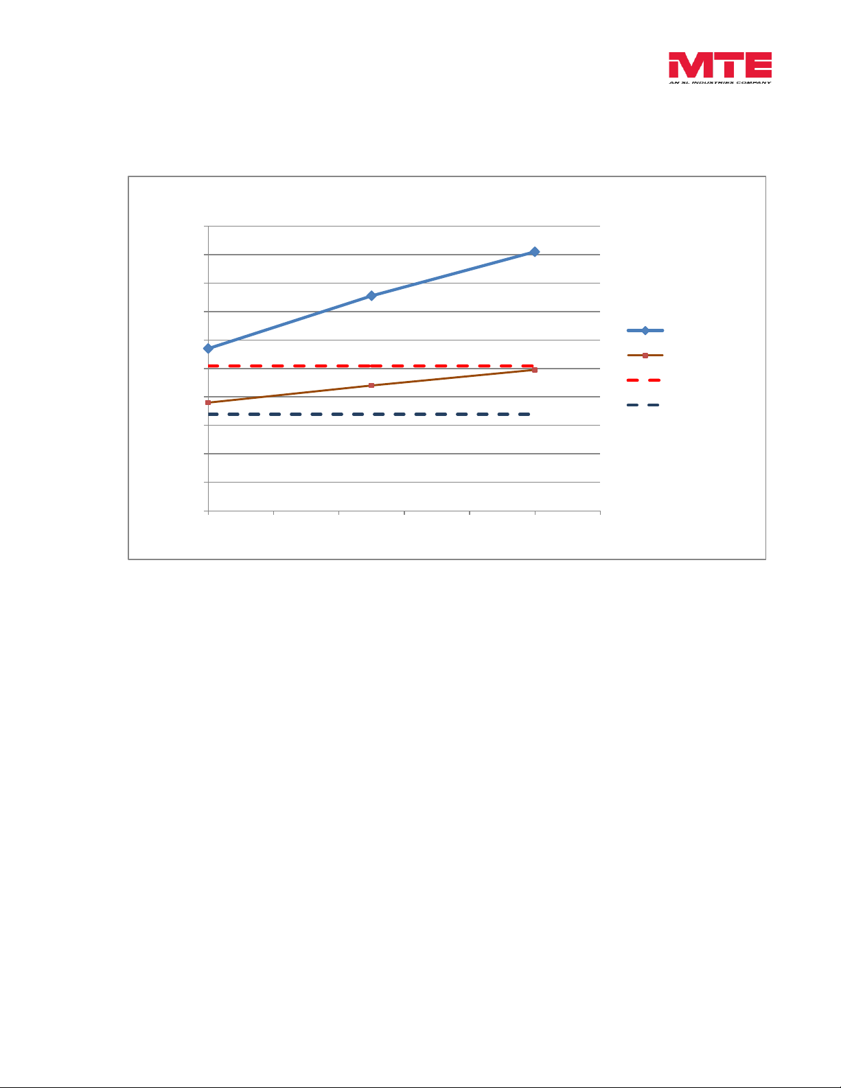
0
0.2
0.4
0.6
0.8
1
1.2
1.4
1.6
1.8
2
0 200 400 600 800 1000 1200
Peak Voltage at Motor (Kvolts)
Cable Length (ft.)
65 Amp DV Sentry Overall Performance - 50hp 480 Vac Motor
Unfiltered
With DVSentry
1.5 x Bus
Drive Bus
5. dV/dt Filter Performance
Table 5-1: Performance Chart
Form: DVS-TRM-E September 2014 REV. 001 14
Page 16
dV Sentry Technical Reference Manual 380V - 600V
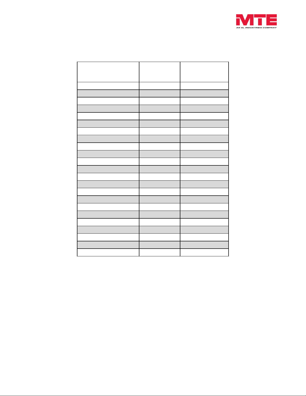
Maximum Output Amps
RMS/Filter Current
Rating Amps RMS
Efficiency
%
Typical Power
Dissipation
Watts*
3
97.5%
227
5
97.5%
227
7
97.5%
227
9
97.5%
227
12
97.5%
227
17
98.0%
334
22
98.4%
278
27
98.5%
267
35
98.8%
260
45
99.1%
219
55
99.3%
297
65
99.4%
376
80
99.5%
336
110
99.6%
363
130
99.6%
393
160
99.7%
412
200
99.7%
449
250
99.8%
550
305
99.8%
616
365
99.8%
703
415
99.8%
703
515
99.8%
1027
600
99.8%
1062
Filter Efficiency + Watt loss
Table 5-2: Filter Efficiency & Watt Loss
*Based on a typical 480V, 60Hz output frequency, 1,000 feet of drive cable, 2kHz carrier
frequency at full load application.
Form: DVS-TRM-E September 2014 REV. 001 15
Page 17
dV Sentry Technical Reference Manual 380V - 600V
0.65
0.7
0.75
0.8
0.85
0.9
0.95
1
1.05
80 90 100 110 120 130
Current Derating Factor
Output Drive Frequency Hertz
DV Sentry Filter Current Derating For Drive Output Frequency
Altitude Derating
Table 5-3: Altitude Derating Curve
Motor Frequency Derating
Form: DVS-TRM-E September 2014 REV. 001 16
Table 5-4: Current Derating for Drive Output Frequency
Page 18
dV Sentry Technical Reference Manual 380V - 600V
WARNING
Prior to installation, please refer to all general warnings on page 4.
Failure to practice this can result in body injury!
WARNING
Input and output wiring to the filter should be performed by authorized
personnel in accordance with NEC and all local electrical codes and
regulations.
WARNING
The filter is designed for use with copper conductors with a minimum
temperature rating of 75 degrees C.
6. HOW TO INSTALL
Installation Checklist
dV/dt filters are supplied in the following mechanical configurations:
Panel mounted assemblies
Floor mounted general purpose NEMA 1/2 & 3R cabinets
Panel filters are designed for mounting in the customer’s enclosure. Include the power
dissipation of the filter along with all the other components located in the panel to determine the
internal temperature rise and cooling requirements of the enclosure. A general guideline is to
allow a side clearance of four (4) inches and a vertical clearance of six (6) inches for proper
heat dissipation and access within the enclosure. Clearances may be less if proper ventilation
exists. Filter components must operate within temperatures specified in this manual or filter
operating life will be compromised. Also be aware of minimum electrical clearances as defined
by the appropriate system safety standard(s). Open panel dV Sentry Filters generate heat and
should be positioned away from heat sensitive components. Ensure that proper panel
orientation is maintained. Keep the capacitors away from reactor heat flow. Avoid locations
where the filter would be subjected to excessive vibrations. Locate the filter as close to the
inverter as possible.
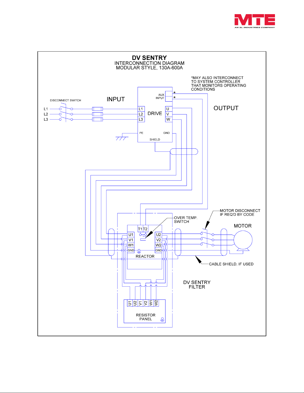
Figure 6-2 contain panel outline drawings for the various current ratings and show proper panel
alignment. For filters above 130 amps refer to Figure 6-3 for the dimensions of the separately
mounted filter. Connect the motor and inverter leads to the reactor terminals to complete the
filter wiring.
General purpose NEMA 1/2 and 3R enclosed filters are designed for floor mounting in an
environment suitable for the enclosure type. Do not install in or near a corrosive environment.
Avoid locations where the filter would be subjected to excessive vibrations. Allow a minimum
side and back clearance of eight (8) inches and front clearance of thirty-six (32 inches for proper
heat dissipation and access.
Form: DVS-TRM-E September 2014 REV. 001 17
Page 19

dV Sentry Technical Reference Manual 380V - 600V
WARNING
The filter must always be grounded with a grounding conductor
connected to ground terminals.
WARNING
For modular units, ensure a 2” X 2” area is cleaned of paint
and varnish on lower mounting bracket for ground connection.
Grounding
*The filter must always be grounded with a grounding conductor connected to ground terminals.
Form: DVS-TRM-E September 2014 REV. 001 18
Page 20
dV Sentry Technical Reference Manual 380V - 600V
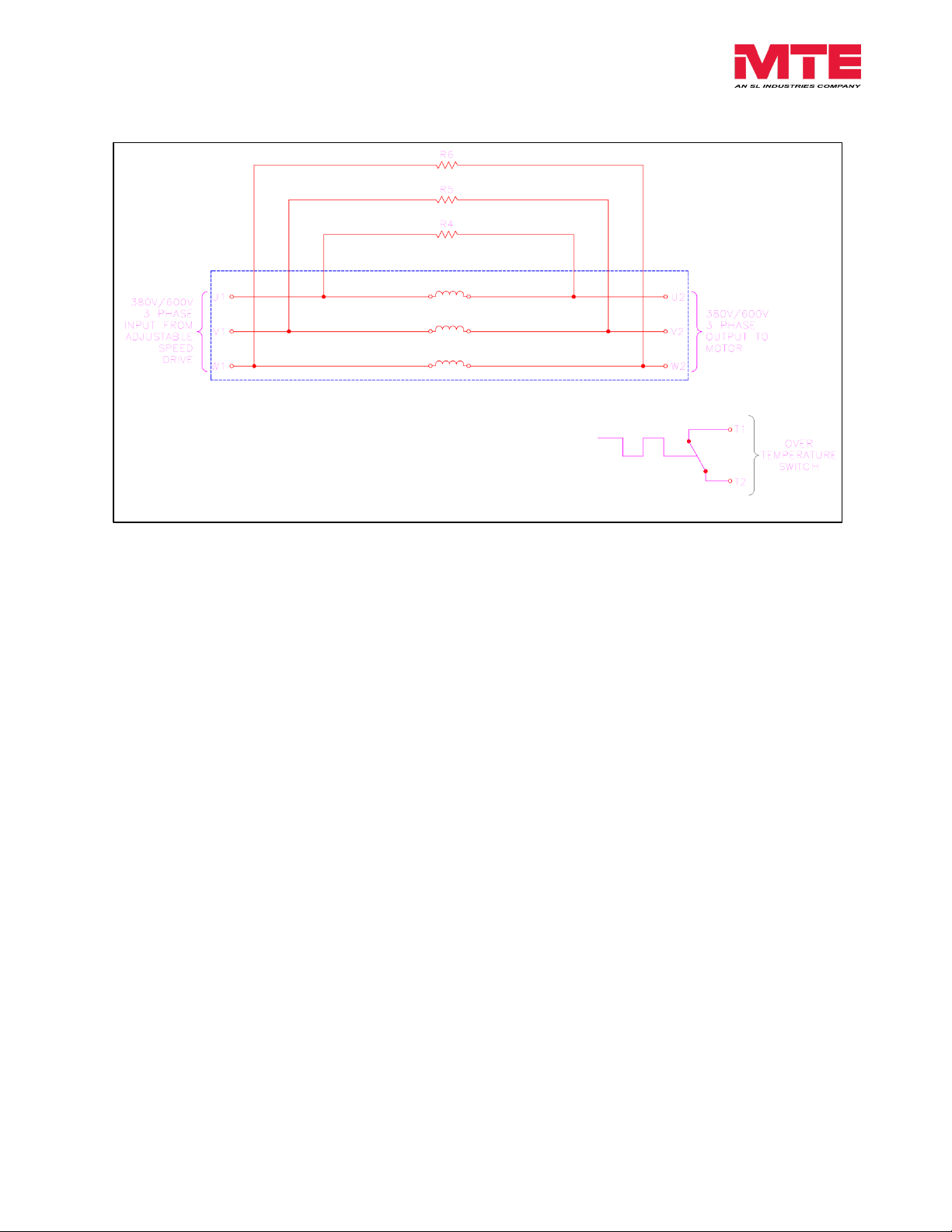
Basic Schematic Diagram
Figure 6-1: Basic Schematic Diagram
Form: DVS-TRM-E September 2014 REV. 001 19
Page 21
dV Sentry Technical Reference Manual 380V - 600V
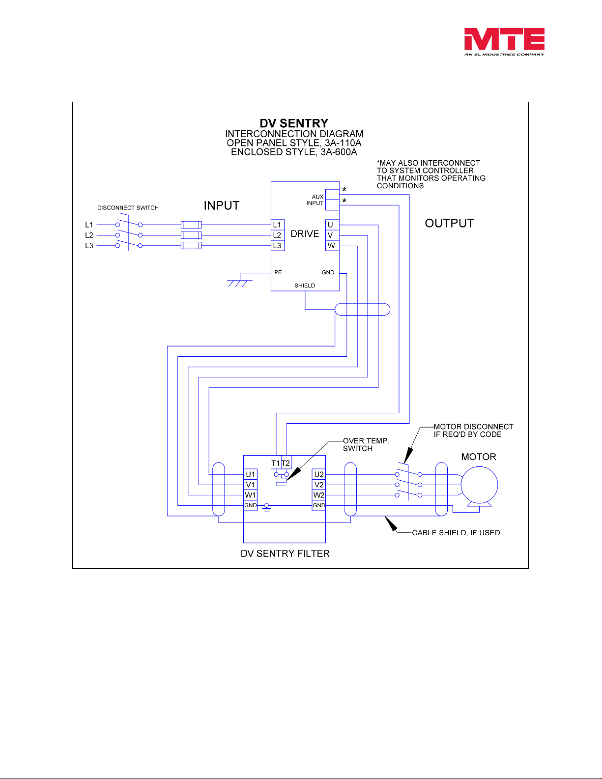
Interconnection Diagram – Panel (3A-110A) and Enclosed (3A-600A)
Figure 6-2: Open Panel and Enclosed Diagram
Form: DVS-TRM-E September 2014 REV. 001 20
Page 22
dV Sentry Technical Reference Manual 380V - 600V
Interconnection Diagram – Modular (130A-600A)
Figure 6-3: Modular Diagram
Form: DVS-TRM-E September 2014 REV. 001 21
Page 23
dV Sentry Technical Reference Manual 380V - 600V
Filter
Rating
(Amps)
DV SENTRY Terminals
Input /Output Power
U1-V1-W1 / U2-V2-W2
Resistor Panel Terminals
U1-V1-W1 / U2-V2-W2
Recommended
Minimum
Wire Size
(AWG)
Terminal
Torque
(in-lbs.)
Resistor Panel Part
Number
Recommended
Wire Size (awg)
Terminal
Torque
(in-lbs.)
3
14
16
N/A
N/A
N/A
5
14
16
N/A
N/A
N/A
7
14
16
N/A
N/A
N/A
9
14
16
N/A
N/A
N/A
12
14
16
N/A
N/A
N/A
17
12
16
N/A
N/A
N/A
22
10
16
N/A
N/A
N/A
27
10
16
N/A
N/A
N/A
35
8
16
N/A
N/A
N/A
45
8
16
N/A
N/A
N/A
55
6
16
N/A
N/A
N/A
65
6
N/A
N/A
N/A
N/A
80
4
N/A
N/A
N/A
N/A
110
2
N/A
N/A
N/A
N/A
130
1
N/A
RESPANEL-012
14
16
160
4(2x) or 2/0
N/A
RESPANEL-012
14
16
200
3(2x) or 3/0
N/A
RESPANEL-012
14
16
250
1 (2x) or
250kcmil
N/A
RESPANEL-013
14
16
305
2/0 (2x)
N/A
RESPANEL-013
14
16
365
3/0 (2x)
N/A
RESPANEL-013
14
16
415
4/0 (2x)
N/A
RESPANEL-013
14
16
515
300kcmil (2x)
N/A
RESPANEL-014
14
16
600
350kcmil(2x)
N/A
RESPANEL-014
14
16
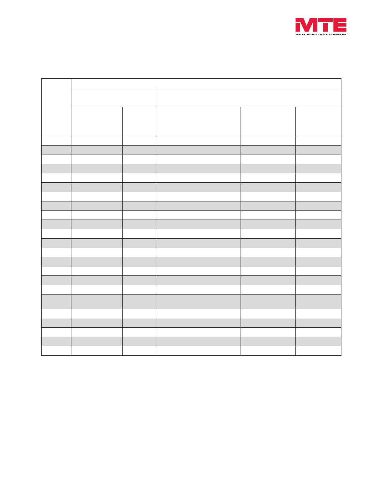
Torque Ratings
Table 6-1: Torque Ratings
Note: To prevent flexing or bending of the coil windings attached to dV Sentry filter, use
appropriate strain relief to prevent stress on terminals. For flat copper terminal tabs, use two
wrenches to tighten customer provided cable mounting hardware.
Note: Refer to reference drawings for termination wire ranges.
Form: DVS-TRM-E September 2014 REV. 001 22
Page 24
dV Sentry Technical Reference Manual 380V - 600V
WARNING
Internal components of the filter are at line potential when the filter is connected
to the drive. This voltage is extremely dangerous and may cause death or severe
injury if you come in contact with it.
WARNING
Use extreme caution to avoid contact with line voltage when checking for power.
INJURY OR DEATH MAY RESULT IF SAFETY PRECAUTIONS ARE NOT
OBSERVED.
WARNING
Damage to equipment or serious injury may occur if the inverter startup
procedures are not observed.
Caution
Damage to the filter may occur if the appropriate output carrier frequency is not
observed.
7. START UP
Startup Checklist
Safety Precautions
Before startup, observe the following warnings and instructions:
Form: DVS-TRM-E September 2014 REV. 001 23
Page 25

dV Sentry Technical Reference Manual 380V - 600V
Sequence of Operation
1. Read and follow safety precautions, including those of drive manufactures.
2. After installation, ensure that:
All filter ground terminals are connected to ground.
Power wiring to the utility, inverter, filter and motor is in accordance with the
installation and connection instructions in Chapter 6.
3. Check that moisture has not condensed on the filter components. If moisture is present,
do not proceed with startup until the moisture has been removed.
4. Refer to the inverter user manual for the inverter startup procedure. Observe all safety
instructions in the inverter user manual.
5. Connect filter temperature safety overload switch into the control circuit so that the drive
will shut down in an overload situation.
6. Set the inverter switching frequency to the appropriate setting.
Form: DVS-TRM-E September 2014 REV. 001 24
Page 26
dV Sentry Technical Reference Manual 380V - 600V
WARNING
INJURY OR DEATH MAY RESULT IF THE DRIVE SAFETY PRECAUTIONS ARE
NOT OBSERVED.
WARNING
When properly installed, this equipment has been designed to provide maximum
safety for operating personnel.
However, hazardous voltages and elevated temperatures exist within the confines
of the enclosure. Servicing should therefore be performed by qualified
personnel only and in accordance with OSHA Regulations.
WARNING
High voltage is used in the operation of this filter. Use Extreme caution to avoid
contact with high voltage when operating, installing or repairing this filter.
INJURY OR DEATH MAY RESULT IF SAFETY PRECAUTIONS ARE NOT
OBSERVED.
PROBLEM:
Voltage is not present at the filter Input terminals.
Possible cause:
Solution:
Power to the inverter is turned off or shut down
Turn power on, check inverter errors
Possible cause:
Solution:
One or more external line fuses are blown.
Verify the continuity of line fuses in all phases, replace as necessary
Possible cause:
Solution:
Damage to inverter – dV/dt interconnect cables
Replace damaged cable
Possible cause:
Solution:
Inverter setup parameters are incorrect
Verify motor current, voltage and shutdown parameters are valid
8. TROUBLESHOOTING
To aid in troubleshooting, two interconnection diagrams, Modular Unit Interconnection Diagram
(p20) and Enclosed Unit Interconnection Diagram (p21) are included, and this table below list
potential problems and solutions.
Table 8-1: Troubleshooting Guide
Form: DVS-TRM-E September 2014 REV. 001 25
Page 27

dV Sentry Technical Reference Manual 380V - 600V
PROBLEM:
dV/dt filter runs Hot
Possible cause:
Solution:
Normal operation, reactor and resistors are > 100 °C
Caution parts are very hot and may cause burns. Follow
installation guidelines for clearances and check for adequate air
flow.
Possible cause:
Solution:
Motor coil damage windings shorted
Replace motor inspect wiring
Possible cause:
Solution:
Heat buildup within enclosure
Provide clearance and venting for filter components.
Check carrier frequency and overload settings.
Possible cause:
Solution:
Multi motor applications create complex loading and resonances
with dV/dt filter.
Use only one dV/dt filter per drive for a single motor only
For multiple line applications, use a sine wave filter.
Form: DVS-TRM-E September 2014 REV. 001 26
Page 28

dV Sentry Technical Reference Manual 380V - 600V
APPENDIX
Reference Drawings
Form: DVS-TRM-E September 2014 REV. 001 27
Page 29
dV Sentry Technical Reference Manual 380V - 600V
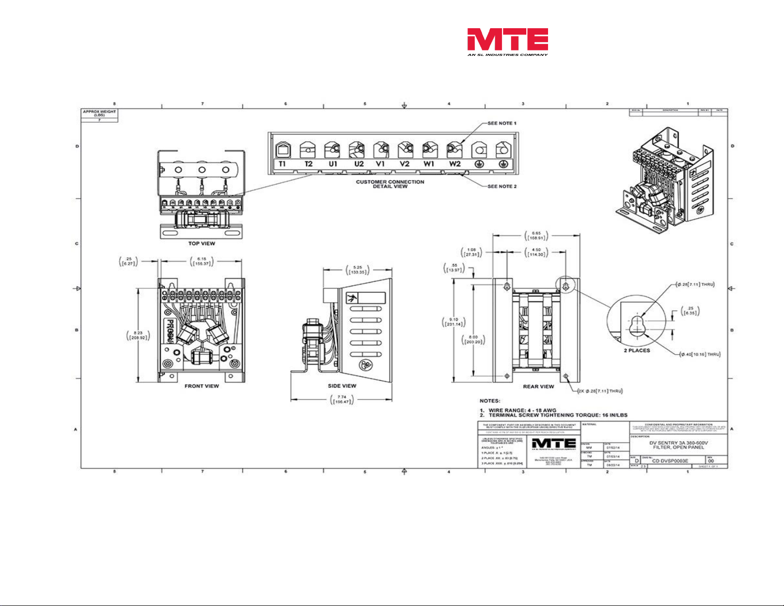
Figure A- 1: DVSP0003E
Form: DVS-TRM-E September 2014 REV. 001 28
Page 30
dV Sentry Technical Reference Manual 380V - 600V
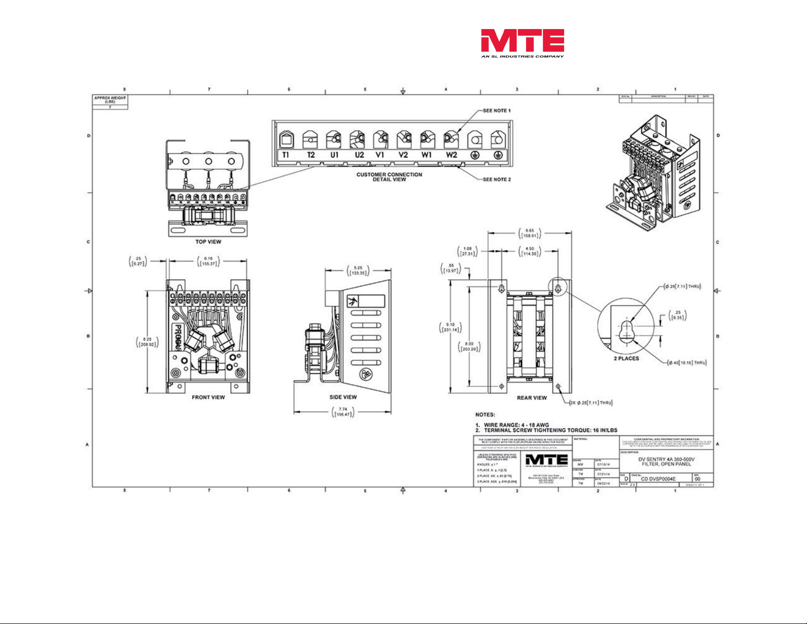
Figure A- 2: DVSP0004E
Form: DVS-TRM-E September 2014 REV. 001 29
Page 31

dV Sentry Technical Reference Manual 380V - 600V
Figure A- 3: DVSP0007E
Form: DVS-TRM-E September 2014 REV. 001 30
Page 32

dV Sentry Technical Reference Manual 380V - 600V
Figure A- 4: DVSP0009E
Form: DVS-TRM-E September 2014 REV. 001 31
Page 33

dV Sentry Technical Reference Manual 380V - 600V
Figure A- 5: DVSP0012E
Form: DVS-TRM-E September 2014 REV. 001 32
Page 34

dV Sentry Technical Reference Manual 380V - 600V
Figure A- 6: DVSP0017E
Form: DVS-TRM-E September 2014 REV. 001 33
Page 35

dV Sentry Technical Reference Manual 380V - 600V
Figure A- 7: DVSP0022E
Form: DVS-TRM-E September 2014 REV. 001 34
Page 36

dV Sentry Technical Reference Manual 380V - 600V
Figure A- 8: DVSP0027E
Form: DVS-TRM-E September 2014 REV. 001 35
Page 37

dV Sentry Technical Reference Manual 380V - 600V
Figure A- 9: DVSP0035E
Form: DVS-TRM-E September 2014 REV. 001 36
Page 38

dV Sentry Technical Reference Manual 380V - 600V
Figure A- 10: DVSP0045E
Form: DVS-TRM-E September 2014 REV. 001 37
Page 39

dV Sentry Technical Reference Manual 380V - 600V
Figure A- 11: DVSP0055E
Form: DVS-TRM-E September 2014 REV. 001 38
Page 40

dV Sentry Technical Reference Manual 380V - 600V
Figure A- 12: DVSP0065E
Form: DVS-TRM-E September 2014 REV. 001 39
Page 41

dV Sentry Technical Reference Manual 380V - 600V
Figure A- 13: DVSP0080E
Form: DVS-TRM-E September 2014 REV. 001 40
Page 42

dV Sentry Technical Reference Manual 380V - 600V
Figure A- 14: DVSP0110E
Form: DVS-TRM-E September 2014 REV. 001 41
Page 43

dV Sentry Technical Reference Manual 380V - 600V
Figure A- 15: DVSP0130E
Form: DVS-TRM-E September 2014 REV. 001 42
Page 44

dV Sentry Technical Reference Manual 380V - 600V
Figure A- 16: DVSP0160E
Form: DVS-TRM-E September 2014 REV. 001 43
Page 45

dV Sentry Technical Reference Manual 380V - 600V
Figure A- 17: DVSP0200E
Form: DVS-TRM-E September 2014 REV. 001 44
Page 46

dV Sentry Technical Reference Manual 380V - 600V
Figure A- 18: DVSP0250E
Form: DVS-TRM-E September 2014 REV. 001 45
Page 47

dV Sentry Technical Reference Manual 380V - 600V
Figure A- 19: DVSP0305E
Form: DVS-TRM-E September 2014 REV. 001 46
Page 48

dV Sentry Technical Reference Manual 380V - 600V
Figure A-20 DVSP0365E
Form: DVS-TRM-E September 2014 REV. 001 47
Page 49

dV Sentry Technical Reference Manual 380V - 600V
Figure A- 21: DVSP0415E
Form: DVS-TRM-E September 2014 REV. 001 48
Page 50

dV Sentry Technical Reference Manual 380V - 600V
Figure A-22: DSVP0515E
Form: DVS-TRM-E September 2014 REV. 001 49
Page 51

dV Sentry Technical Reference Manual 380V - 600V
Figure A-23: DVSP0600E
Form: DVS-TRM-E September 2014 REV. 001 50
Page 52

dV Sentry Technical Reference Manual 380V - 600V
Form: DVS-TRM-E September 2014 REV. 001 51
Page 53

dV Sentry Technical Reference Manual 380V - 600V
Figure A-24: DVSG0003E
Form: DVS-TRM-E September 2014 REV. 001 52
Page 54

dV Sentry Technical Reference Manual 380V - 600V
Figure A-25: DVSG0004E
Form: DVS-TRM-E September 2014 REV. 001 53
Page 55

dV Sentry Technical Reference Manual 380V - 600V
Figure A-26: DVSG0007E
Form: DVS-TRM-E September 2014 REV. 001 54
Page 56

dV Sentry Technical Reference Manual 380V - 600V
Figure A-27: DVSG0009E
Form: DVS-TRM-E September 2014 REV. 001 55
Page 57

dV Sentry Technical Reference Manual 380V - 600V
Figure A-28: DVSP0012E
Form: DVS-TRM-E September 2014 REV. 001 56
Page 58

dV Sentry Technical Reference Manual 380V - 600V
Figure A-29: DVSG0017E
Form: DVS-TRM-E September 2014 REV. 001 57
Page 59

dV Sentry Technical Reference Manual 380V - 600V
Figure A-30: DVSG0022E
Form: DVS-TRM-E September 2014 REV. 001 58
Page 60

dV Sentry Technical Reference Manual 380V - 600V
Figure A-31: DVSG0027E
Form: DVS-TRM-E September 2014 REV. 001 59
Page 61

dV Sentry Technical Reference Manual 380V - 600V
Figure A-32: DVSG0035E
Form: DVS-TRM-E September 2014 REV. 001 60
Page 62

dV Sentry Technical Reference Manual 380V - 600V
Figure A-33: DVSG0045E
Form: DVS-TRM-E September 2014 REV. 001 61
Page 63

dV Sentry Technical Reference Manual 380V - 600V
Figure A-34: DVSG0055E
Form: DVS-TRM-E September 2014 REV. 001 62
Page 64

dV Sentry Technical Reference Manual 380V - 600V
Figure A-35: DVSG0065E
Form: DVS-TRM-E September 2014 REV. 001 63
Page 65

dV Sentry Technical Reference Manual 380V - 600V
Figure A-36: DVSG0080E
Form: DVS-TRM-E September 2014 REV. 001 64
Page 66

dV Sentry Technical Reference Manual 380V - 600V
Figure A-37: DVSG0110E
Form: DVS-TRM-E September 2014 REV. 001 65
Page 67

dV Sentry Technical Reference Manual 380V - 600V
Figure A-38: DVSG0130E
Form: DVS-TRM-E September 2014 REV. 001 66
Page 68

dV Sentry Technical Reference Manual 380V - 600V
Figure A-39: DVSG0160E
Form: DVS-TRM-E September 2014 REV. 001 67
Page 69

dV Sentry Technical Reference Manual 380V - 600V
Figure A-40: DVSG0200E
Form: DVS-TRM-E September 2014 REV. 001 68
Page 70

dV Sentry Technical Reference Manual 380V - 600V
Figure A-41: DVSG0250E
Form: DVS-TRM-E September 2014 REV. 001 69
Page 71

dV Sentry Technical Reference Manual 380V - 600V
Figure A-42: DVSG0305E
Form: DVS-TRM-E September 2014 REV. 001 70
Page 72

dV Sentry Technical Reference Manual 380V - 600V
Figure A-43: DVSG0365E
Form: DVS-TRM-E September 2014 REV. 001 71
Page 73

dV Sentry Technical Reference Manual 380V - 600V
Figure A-44: DVSG0415E
Form: DVS-TRM-E September 2014 REV. 001 72
Page 74

dV Sentry Technical Reference Manual 380V - 600V
Figure A-45: DVSG0515E
Form: DVS-TRM-E September 2014 REV. 001 73
Page 75

dV Sentry Technical Reference Manual 380V - 600V
Figure A-46: DVSG0600E
Form: DVS-TRM-E September 2014 REV. 001 74
Page 76

dV Sentry Technical Reference Manual 380V - 600V
Figure A-47: DVSW0003E
Form: DVS-TRM-E September 2014 REV. 001 75
Page 77

dV Sentry Technical Reference Manual 380V - 600V
Figure A-48: DVSW0004E
Form: DVS-TRM-E September 2014 REV. 001 76
Page 78

dV Sentry Technical Reference Manual 380V - 600V
Figure A-49: DVSW0007E
Form: DVS-TRM-E September 2014 REV. 001 77
Page 79

dV Sentry Technical Reference Manual 380V - 600V
Figure A-50: DVSW0009E
Form: DVS-TRM-E September 2014 REV. 001 78
Page 80

dV Sentry Technical Reference Manual 380V - 600V
Figure A-51: DVSW0012E
Form: DVS-TRM-E September 2014 REV. 001 79
Page 81

dV Sentry Technical Reference Manual 380V - 600V
Figure A-52: DVSW0017E
Form: DVS-TRM-E September 2014 REV. 001 80
Page 82

dV Sentry Technical Reference Manual 380V - 600V
Figure A-53: DVSW0022E
Form: DVS-TRM-E September 2014 REV. 001 81
Page 83

dV Sentry Technical Reference Manual 380V - 600V
Figure A-54: DVSW0027E
Form: DVS-TRM-E September 2014 REV. 001 82
Page 84

dV Sentry Technical Reference Manual 380V - 600V
Figure A-55: DVSW0035E
Form: DVS-TRM-E September 2014 REV. 001 83
Page 85

dV Sentry Technical Reference Manual 380V - 600V
Figure A-56: DVSW0045E
Form: DVS-TRM-E September 2014 REV. 001 84
Page 86

dV Sentry Technical Reference Manual 380V - 600V
Figure A-57: DVSW0055E
Form: DVS-TRM-E September 2014 REV. 001 85
Page 87

dV Sentry Technical Reference Manual 380V - 600V
Figure A-58: DVSW0065E
Form: DVS-TRM-E September 2014 REV. 001 86
Page 88

dV Sentry Technical Reference Manual 380V - 600V
Figure A-59: DVSW0080E
Form: DVS-TRM-E September 2014 REV. 001 87
Page 89

dV Sentry Technical Reference Manual 380V - 600V
Figure A-60: DVSW0110E
Form: DVS-TRM-E September 2014 REV. 001 88
Page 90

dV Sentry Technical Reference Manual 380V - 600V
Figure A-61: DVSW0130E
Form: DVS-TRM-E September 2014 REV. 001 89
Page 91

dV Sentry Technical Reference Manual 380V - 600V
Figure A-62: DVSW0160E
Form: DVS-TRM-E September 2014 REV. 001 90
Page 92

dV Sentry Technical Reference Manual 380V - 600V
Figure A-63: DVSW0200E
Form: DVS-TRM-E September 2014 REV. 001 91
Page 93

dV Sentry Technical Reference Manual 380V - 600V
Figure A-64: DVSW0250E
Form: DVS-TRM-E September 2014 REV. 001 92
Page 94

dV Sentry Technical Reference Manual 380V - 600V
Figure A-65: DVSW0305E
Form: DVS-TRM-E September 2014 REV. 001 93
Page 95

dV Sentry Technical Reference Manual 380V - 600V
Figure A-66: DVSW0365E
Form: DVS-TRM-E September 2014 REV. 001 94
Page 96

dV Sentry Technical Reference Manual 380V - 600V
Figure A-67: DVSW0415E
Form: DVS-TRM-E September 2014 REV. 001 95
Page 97

dV Sentry Technical Reference Manual 380V - 600V
Figure A-68: DVSW0515E
Form: DVS-TRM-E September 2014 REV. 001 96
Page 98

dV Sentry Technical Reference Manual 380V - 600V
Figure A-69: DVSW0600E
Form: DVS-TRM-E September 2014 REV. 001 97
Page 99

dV Sentry Technical Reference Manual 380V - 600V
Figure A-70: RESPANEL-012
Form: DVS-TRM-E September 2014 REV. 001 98
Page 100

dV Sentry Technical Reference Manual 380V - 600V
Figure A-71: RESPANEL-013
Form: DVS-TRM-E September 2014 REV. 001 99
 Loading...