

Page 1

SPRAYERS
Landscape Maintenance Equipment
OPERATOR’S MANUAL
Model No. Polyethylene Tank Sprayers Model No. Fiberglass Tank Sprayers
SY50 50 Gallon w/4.0-HP Kawasaki Engine
SY50P 50 Gallon w/Manual-Reel SYS300 300 Gallon Split w/8.0-HP Kawasaki Engine
SY50PE 50 Gallon Sprayer Package SYS300PE 300 Gallon Split Tank Package
SY100 100 Gallon w/5.5-HP Kawasaki Engine
SY100PE 100 Gallon Sprayer Package
SY200 200 Gallon w/5.5-HP Kawasaki Engine
SY200PE 200 Gallon Sprayer Package
SY300 300 Gallon w/5.5-HP Kawasaki Engine
SY300PE 300 Gallon Sprayer Package
The Following Sprayers have Mechanical Agitation
Page 2

TABLE OF CONTENTS
Foreword.....................................................................................................................................3
Safety Precautions......................................................................................................................3
A. General ....................................... ...... ....... ...... ....... ...... ............................................. . ...... .3
B. Related to Gasoline or Engines .......................................................................................3
C. Related to Batteries .........................................................................................................3
Specifications...........................................................................................................................4,5
Operating Instructions.................................................................................................................6
A. Controls................... ....... ...... ....... ...... ....... ...... ....... ...... .....................................................6
1. Engine Choke................................................................................................................6
2. Engine Throttle..............................................................................................................6
3. Ignition Switch ...............................................................................................................6
4. Rewind Pull-Cord Starter...............................................................................................6
5. Valves............................................................................................................................6
6. Pressure Gauge ............................................................................................................6
7. Pressure Regulator ....................................................................................................6,7
B. Set up............................. ...... ....... ...... ....... ...... ....... ...... ....... ...... ....................................... .7
1. General..........................................................................................................................7
2. Installation in a Van or Pickup Truck.............................................................................7
3. Wiring.........................................................................................................................7,8
C. Spraying...........................................................................................................................8
1. Starting the Sprayer - Gasoline-Powered......................................................................8
2. Calibration ................................................................................................................ 9,10
a. Hand Spraying ........................................................................................................9
b. Boom Spraying .....................................................................................................10
3. Tips on Spraying .....................................................................................................11-13
a. Mixing Dry-Bagged Products for Sprayer Use......................................................11
b. Use of the MTD Pro Lawn Gun............................................................................. 11
c. Use of the MTD Pro Spray Wand .........................................................................12
d. Use of High Pressure Guns ..............................................................................12,13
4. Cleaning the Sprayer...................................................................................................11
Maintenance Instructions......................................................................................................11,12
A. Engine Maintenance Schedule ......... ....... ...... ....... ...... ....... ...... ...... ................................11
B. Battery............................ ...... .............................................. ...... ...... ................................ 11
C. Pump.............................................................................................................................. 11
D. Agitator...........................................................................................................................11
E. Belt Adjustment.............. ...... ....... ...... ....... ...... ....... ...... ....... ...... ...... ................................12
F. Tank ...............................................................................................................................12
G. In-Line Strainer ..............................................................................................................12
H. Hose............................................................................................................................... 12
I. Storage and Winterizing ..................................................................................................12
Troubleshooting Guide .............................................................................................................13
2
Page 3

FOREWORD
The MTD Pro line of sprayers is designed to provide professional turfgrass managers with reliable spray
equipment. The line includes both polyethylene and fiberglass tank sprayers. They are gasoline powered and
range in maximum output from 6.0 GPM to 14 GPM. This manual presents the operating and maintenance
instructions necessary to keep your MTD Pro Sprayer at peak efficiency. If properly operated and maintained,
your MTD Pro Sprayer will provide dependable service.
SAFETY PRECAUTIONS
A. General
No one should operate or maintain this
1.
sprayer who has not read this manual.
2. Keep adults, children and pets away from the
sprayer and the area to be sprayed.
3. If truck or trailer mounted, make certain the
sprayer is securely bolted to the frame of the
truck or trailer.
4. When spraying pesticides:
ALWAYS FOLLOW THE DIRECTIONS ON
a.
THE LABEL
b.Avoid breathing vapors.
c.Avoid contact with skin, eyes or clothing.
d.Wear rubber boots or rubberized shoes.
e.Wear work clothes with long-sleeved shirts
and long-legged pants.
f.Change to clean clothing daily.
g.Wash hands and face before eating or
smoking.
h.After spraying bathe thoroughly.
5. Wear a face shield and rubber gloves when
handling concentrates.
6. Do not remove any shields, guards or safety
devices from the sprayer. If a shield, guard or
safety device is damaged or does not function,
repair or replace it before operating the sprayer.
B. Related to Gasoline or Engines
GASOLINE IS HIGHLY FLAMMABLE
1.
RESPECT IT!
2. Do not smoke or permit others to smoke while
handling gasoline.
3. Always use approved containers for gasoline.
4. Always shut off a gas oline engine and permit it
to cool before removing the cap of the fuel tank.
5. Always fill the fuel tank outdoors.
6. If the fuel container spout will not fi t INSIDE the
fuel tank opening, use a funnel.
7. When filling the fuel tank, stop when the
gasoline reaches 1/2 inch from the top. This
space must be left for expansion. DO NOT
OVEFIFILL!
8. Wipe up any spilled gasoline.
9. To prevent hand or arm injury, always pull
engine starter cord rapidly to avoid kickback.
10. Never run a gasoline engine indoors without
adequate ventilation. Exhaust fumes are
deadly.
11.To avoid serious burns , do not touc h a gasol in e
engine, the exhaust pipe or muffler while the
engine is running or un til it has cooled after it
has been shut off.
C. Related to Batteries
1. The electrolyte in a lead-acid battery is
dilute sulfuric acid which is a very
dangerous and corrosive liquid. Always
wear safety glasses or goggles and rubber
gloves when working on a lead-acid
battery.
2. Do not overfill a lead-acid bat tery when filling
the cells with distilled water.
3. Lead-acid batteries generate hydrogen and
oxygen gases which form an explosive
mixture. Keep sparks and flames away at all
times.
3
Page 4

SPECIFICATIONS
TANKS
Polyethylene:
polyethylene tanks in 50, 100, 200 or 300 gallon
capacities. All tanks are rectangular except the 300
gallon tank which is round. All tanks have 10 inch
fillwells equipped with strainer baskets and splashguard covers. All of the tanks have gallonage markers
molded into the plastic.
Fiberglass:
of strong fiberglass mat and an inside layer of clearcoat for wear resistance. Fiberglass tank baffles are
built into the 300 gallon tank to control surging. The
300 gallon tank has 16'' fillwells with strainer baskets
and screw-on lids for leak resistance. The tank has a
replaceable sight tube and a calibrated gallonage
indicator.
Sturdy, rotational molded,
Outer, white gel-coat layer, three layers
FRAMES
Polyethylene and Fiberglass:
frames are constructed of eleven gauge steel. 100,
200 and 300 gallon frames are constructed of ten
gauge steel while engine and pump bases are formed
into channels from seven gauge steel and then
electric-welded to the frames to form a rigid, unitized
assembly. All frames have punched holes to accept
optional accessories.
50 gallon
ENGINES/PUMPS
Gas-Powered Polyethylene
50 Gallon:
recoil-start engine which is directly coupled through
a gear reduction to a twin-diaphragm pump (6.0GPM max. or 275-psi max.)
100, 200 and 300 gallon
air-cooled, recoil-start, gear reduction engine which
drives a twin-diaphragm pump (9.5-GPM max. or
550-psi max.).
Gas-Powered Fiberglass
300 Gallon:
recoil-start engine powers a 14.0 GPM and 550 PSI,
twin-piston, diaphragm pump through a pulley and
belt drive.
4.0-HP Kawasaki, 4-cycle, air-cooled,
: 5.5-HP Kawasaki, 4-cycle,
8.0-HP Kawasaki, 4- cycle, air-cooled,
IN-LINE STRAINER
All sprayers have a suction strainer with a 30-mesh
stainless steel screen located on the inlet side of the
pump.
AGITATION
Polyethylene
50 Gallon:
300 Gallon:
Fiberglass
300 Gallon:
stainless steel shaft with replaceable stainless steel
paddles.
Bypass, triple-jet agitation.
Pressurized, triple-jet agitation.
Mechanical agitation with a full-length,
100, 200 and
PRESSURE REGULATOR
(Gas-powered only)
Adjustable pressure regulating valve with a
glycerine-dampened pressure gauge (0-860 psi).
NET WEIGHT
Polyethylene
50 Gallon: 125 lbs.
100 Gallon: 237 lbs.
200 Gallon: 336 lbs.
300 Gallon: 422 lbs.
Fiberglass
8 HP Engine
675 lbs.
(Without reel or hose.)
DIMENSIONS
Polyethylene
50 Gallon:
Length: 54" (Includes 6 inch bumper.)
Tank Width: 19"
Frame Width: 19-1/4"(24" with hose reel)
Height: 26", (43" with hose reel)
100 Gallon:
Length: 48", 49" to drain cap
Tank Width: 38"
Frame Width: 38"
Height (to top of tank): 34", (45" w/hose reel)
200 Gallon:
Length: 65", (66" to drain cap)
Tank Width: 39"
Frame Width: 38"
Height (to top of tank): 40", (46" w/hose reel)
300 Gallon:
Length: 88", 89" to drain cap
Tank Width: 41"
Frame Width: 38"
Height (to top of tank): 47"
Fiberglass
300 Gallon:
Length:85", (86” to drain cap)
Width: 39"
Height: 39", (46" w/ hose reel)
4
Page 5

SPECIFICATIONS
OPTIONS AVAILABLE
Manual Hose Reel Kits
590-529-195
•
hose and hardware for 50 gallon Sprayers.
590-531-195
•
hose and hardware for 100/200/300 gallon
Sprayers.
Hose Reel Mount Kits
590-530-195
•
brackets and hardware for 50 gallon Sprayers.
590-532-195
•
upright mounts, bracke ts and hardware for 100/
200/300 gallon Sprayers.
Electric Hose Reel Kits
000-000-000
•
hose and hardware for 50 gallon sprayers.
000-000-000
•
hose and hardware for 100/200/300 gallon
sprayers.
Reel Roller Guide Kits:
590-527-195
•
hardware for 50 gallon Sprayers.
590-528-195
•
hardware for 100/200/300 gallon Sprayers.
Hose Assemblies:
590-524-195
•
PVC Spray Hose 300' long with fittings for 50
gallon Sprayers.
590-523-195
•
PVC/Urethane Spray Hose 300' long with
fittings for 100/200/300 gallon Sprayers.
Spray Wand & Gun:
590-526-195
•
for 50 gallon Sprayers.
590-525-195
•
200/300 gallon Sprayers.
- Manual Hose Reel Kit: includes
- Manual Hose Reel Kit: includes
- Hose Reel Mount Kit: includes
- Hose Reel Mount Kit: includes
- Electric Hose Reel Kit: includes
- Electric Hose Reel Kit: includes
- Reel Roller Guide Kit: includes
- Reel Roller Guide Kit: includes
- 3/8”, 300 psi working pressure,
- 1/2”, 800-psi working pressure,
- Spray Wand w/high volume tip
- Tree and Shrub Gun for 50/100/
Trailers
56A-743T-195
•
and bolt on tongue assembly with a pin-hitch
and jack-stand, (2)13 x 5.00-6 tires.
56A-744T-195
•
and bolt on tongue assembly with a pin-hitch
and jack-stand, (2) 18 x 9.50-8 turf tires.
56A-740T-195
•
axles and bolt on tongue assembly with pinhitch and jack-stand, (4)18 x 9.50-8 turf tires.
56A-740A-195
•
and bolt on tongue assembly with a pin-hitch
and jack-stand, (2)11 L-15 flotation AG tires.
56A-740A-195
•
and bolt on tongue assembly with a pin-hitch
and jack-stand, (2)11 L-15 flotation AG tires.
- 50 Gal. Sprayer: Bolt on axle
- 100 Gal. Sprayer: Bolt on axle
- 200 Gal. Sprayer: Bolt on dual
- 200 Gal. Sprayer: Bolt on axle
- 300 Gal. Sprayer: Bolt on axle
Sprayer Booms
590-533-195
bodies w/diaphragm check valves w/hollow cone spray
tips. Schedule-80 PVC tubing. Valve tech valve for on/
off control. Brackets and hardware to mount to
sprayer. Connecting hoses form pump to tech valve
and tech valve to spray boom.
590-534-195
bodies w/diaphragm check valves w/hollow cone spray
tips. Schedule-80 PVC tubing. Valve tech valve for on/
off control. Brackets and hardware to mount to
sprayer. Connecting hoses from pump to tech valve
and tech valve to spray boom.
21 foot, three-section wet boom, 1/2" ID, 304 stainless
steel piping with removable end caps for clean out, 12FL5VO wide angle full cone spray tips on 20" centers.
0 to 160 psi glycerin filled pressure gauge, ratchet
valve, mounting bracket and all related plumbing.
- 16' Spray Boom Kit: includes 12 nozzle
- 20' Spray Boom Kit: includes 13 nozzle
5
Page 6

OPERATING INSTRUCTIONS
A.CONTROLS
1. Engine Choke
There are usually two moving levers on the side of
an engine near the carburetor. One of these is the
choke, the other is the throttle. The choke lever
should be moved all the way to the "CHOKE"
position when starting a cold engine. After the
engine starts, slowly move the lever all the way
back to the "RUN" position as the engine warms
up. A warm engine should not be choked.
2. Engine Throttle
The second moving lever on the side of an engine
near the carburetor is the throttle. For starting,
place the lever at 50% of the maximum RPM. For
pump pressures up to about 100 psi, the throttle
should be set at 30% of the maximum RPM. For
maximum pressures, the throttle should be set at
"FAST" or 100% of the maximum RPM.
3. Ignition Switch
NOTE: Make sure the pump is not under
pressure before trying to start the engine.
a. Recoil-Start Engines
On some engines, moving the throttle lever to
"OFF" or "STOP", while the engine is running
will short out the magneto and stop the
engine. On other engines, a separate lever or
knob on the side or top of the engine functions
as an ignition switch. They have two positions:
"OFF" and "START". They must be placed in
the "START" position before trying to start the
engine. Moving the lever or turning the knob
back to the "OFF" position while the engine is
running will short out the magneto and stop
the engine.
b. Electric-Start Engines
Automotive-type key switches are used as
ignition switches and are usually found on the
side or top of the engine. A clockwise 45° turn
closes the ignition circuit and turning the
switch further against spring pressure starts
the engine. The key should always be
removed from the switch if the sprayer is to be
left unattended.
4. Rewind Pull-Cord Starter
Located on the right side of the engine. To start
the engine, set the choke and the throttle and
grasp the starter grip and pull slowly until the
starter engages. Then pull the cord rapidly to
overcome compression, prevent kickback and start
the engine. Repeat if necessary with the choke
opened slightly. When the engine starts, slowly
open the choke all the way.
5. Valves
There are several ball valves used on the
sprayers. They serve as pump outlets and are
mounted under the pressure regulator. Ball valves
operate with a quarter turn movement of the
handle. When the handle lines up with the
direction of flow, the valve is open. When the
handle is at a 90° angle to the direction of flow, the
valve is closed. There is a gate valve in the suction
line at the front of the engine plate near the drain
fitting. The handle should be turned all the way
counterclockwise to open the valve and all the way
clockwise to close the valve. To drain the tank, the
cap must be removed from the drain fitting and the
gate valve must be opened.
6. Pressure Gauge
Mounted in the pressure regulator housing, the
pressure gauge indicates the pressure in the
output line to the spray gun, wand or boom and the
line to the hydraulic agitator, if used. The gauge is
graduated in pounds per square inch (psi) and
kilopascals (kPa).
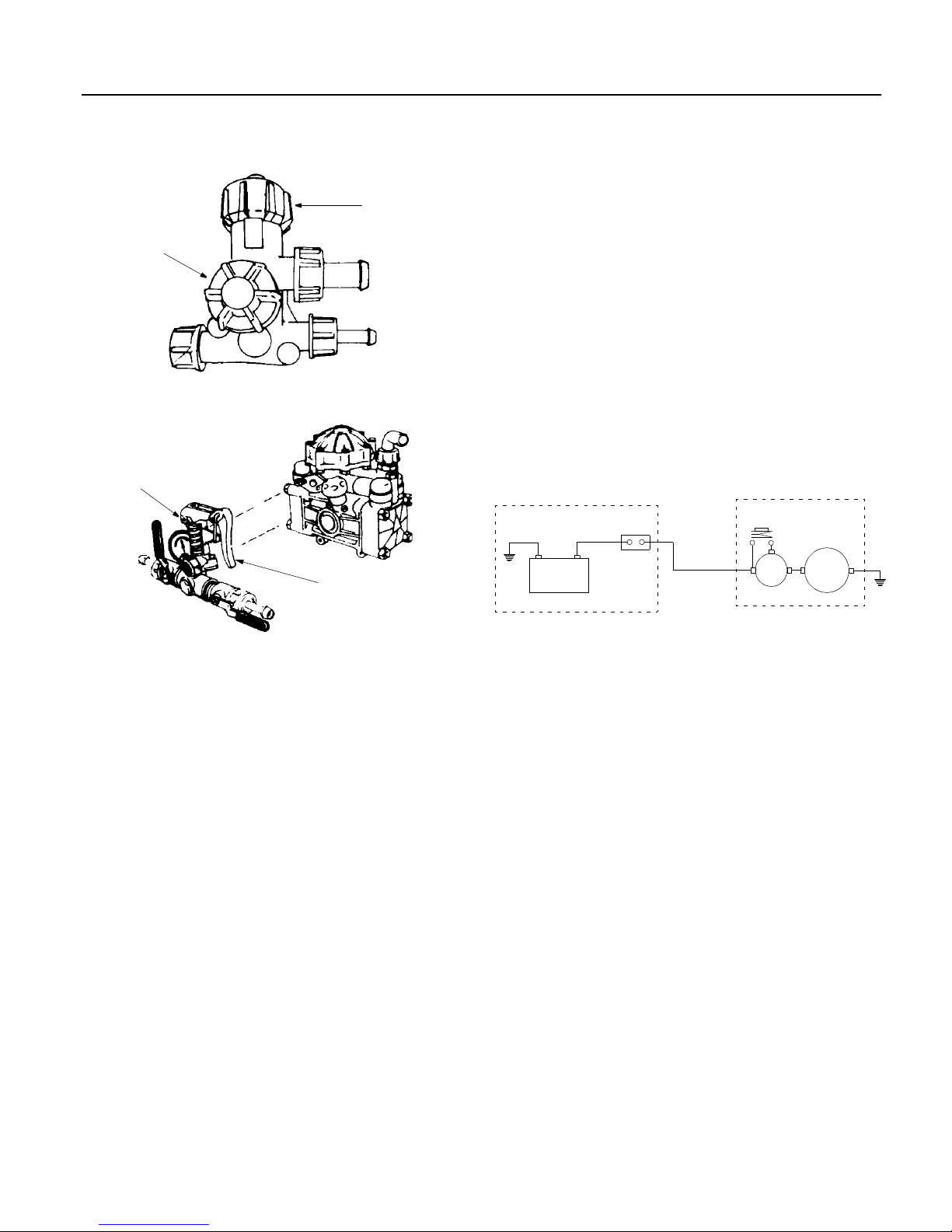
7. Pressure Regulator
Located on the side of the pump opposite the drive
shaft. There are different styles of regulators, but
they all function in the same way. A spring-loaded
plunger rests against a valve seat which forces the
pump flow to the outlets. The springs are opposed
by the hydraulic pressure generated by the pump.
If this pressure exceeds the spring pressure, the
plunger is lifted off of its seat and part or all of the
flow goes to bypass. All of the pressure regulators
have operating levers which in one position,
remove the spring pressure from the plunger and
permit the pump's flow to dump to bypass and in
the other position, apply the spring pressure to the
plunger and force the pump's flow to the outlets.
One valve has a toggle-type operating lever with a
ball which can be hooked in different notches for
adjustment. Another regulator has a knob that
turns about 90° from "OFF" to "ON". Still another
has a hinged part of the plunger shaft work as the
operating lever. All of the regulators also have a
means for adjusting the operating pressure. This is
a threaded knob, a ring or a brass adjustment nut
which when threaded down toward the base of the
pressure regulator, increases the spring pressure.
Normally, the regulator should be set to provide
about 100 psi with both output ball valves closed.
Then the output ball valve to the application device
is opened completely and with bypass or
pressurized jet agitation, the output ball valve to
the agitator line is adjusted to provide the desired
6
Page 7
OPERATING INSTRUCTIONS
flow rate and with the mechanical agitation, the
pressure regulator is adjusted to provide the
desired flow rate.
Adjustment
Operating
Knob
Pressure Regulator on 6.0 GPM Pump
Brass Pressure
Adjustment Nut
Operating Lever
Pressure
Regulator
Knob
3. Wiring
The following instructions are for providing
electrical power to the electric hose reel if your
sprayer is so equipped. The vehicle's or sprayer's
battery should be a 12-Volt DC automotive-type.
THE VEHICLE CAN HAVE EITHER A POSITIVE
OR NEGATIVE GROUND SYSTEM AND
THEREFORE POLARITY IS NOT SHOWN ON
THE WIRING DIAGRAM.
Materials furnis hed if your sprayer is equipped with an
electric hose reel:
1 - 40 amp. Circuit Breaker
5 - Cable Ties
2 - Insulated Ring Terminal s #8 Wire x 5/16" Stud
2 - Insulated Ring Terminal s #8 Wire x #10 Stud
25 ft. of #8 Insulated Wire
Tools Needed
Wire Cutter, Crimping Tool, Screwdriver, Adjustable
Wrench and Electric Drill.
ENGINE COMPARTMENT
40 amp
12 V. Vehicle
Battery
Circuit
Breaker
# 8 Wire
to Sprayer
SPRAYER
Push-button
Switch
Solenoid
Reel
Motor
Pressure Regulator on 9.5 - 14 GPM Pump
B.SET-UP
1. General
Check all the bolts on the sprayer for tightness.
Make certain all hose clamps are tight. Check that
the tank straps are tight on poly-tank sprayers.
Check that the pulleys and belts are tight and
aligned on fiberglass tank sprayers. (For pulley
and belt adjustment, see the Maintenance Section
on page 13.) Check that electrical connections are
sound on electric sprayers.
2. Installation In a Van or Pickup Truck
Once the sprayer is in the desired position in your
van or pickup truck, it should be securely bolted
through the truck bed to the vehicle's frame. Bolts
should be used at each corner of the sprayer's
frame and should be either cap screws placed
through the holes punched in the frame for this
purpose or large U-bolts or J-bolts over the
sprayer's steel frame and down through the truck
bed to the vehicle's frame. Bolts of at least 3/8"
diameter should be used for a 50 gallon sprayer,
1/2" diameter for a 100 gallon sprayer, 5/8"
diameter for a 200 gallon sprayer and 7/8" for a
300 gallon sprayer. Mounting hardware is not
supplied for the sprayer because the installation
will vary with each vehicle.
WIRING DIAGRAM
Wiring Instructions
a. DISCONNECT THE GROUND CABLE FROM
THE VEHICLE'S BATTERY.
b. Install the circuit breaker in the engine
compartment near the vehicle's battery but away
from sources of heat or humidity.
c. Cut the required length of #8 wire to reach from
the ungrounded terminal of the battery to the
terminal marked "BAT" on the circuit breaker.
Attach a 5/16" ring terminal on one end and a #10
ring terminal on the other end. Connect this wire
to the ungrounded terminal of the battery and the
terminal marked "BAT" on the circuit breaker.
d. Attach a #10 ring terminal to one end of the
remaining #8 wire and connect it to the terminal
marked "AUX" on the circuit breaker.
Work the loose end of the #8 wire either under the
vehicle or through the fire wall (depending on your
vehicle) to reach the sprayer. Take advantage of
any existing cable ties or clamps along the way to
support the wire and use the enclosed cable ties
where needed.
7
Page 8

OPERATING INSTRUCTIONS
e. Bring the wire to the solenoid mounted on the
reel frame and cut it off at the proper length.
Attach a 5/16" ring terminal to the wire and
connect it to the large solenoid terminal opposite
the one to which the reel motor lead is
connected.
f. Ground the frame of the sprayer to the vehicle
body as follows:
NOTE:
the frame of the vehicle with bolts passing through
or over the sprayer's frame and the vehicle's
frame, the sprayer Is grounded, this step may be
omitted.
f. Reconnect the ground cable removed from the
g. Test the circuit by pulling some hose from the
If the sprayer has been properly bolted to
1. Locate a vehicle body bolt near or under the
sprayer's frame that can be easily removed
and replaced.
2. Place a bolt through the nearest punched hole
in the sprayer's frame.
3. Cut the remaining #8 wire to the proper length
to reach between these two bolts. Strip
approximately one inch of insulation from each
end of the wire.
4. Remove the bolts or nuts and scratch off any
paint that would prevent making metal to metal
contact.
5. Wrap the stripped end of the wire around each
bolt and replace the bolts or nuts.
battery in Step a.
reel and then pushing the reel switch located on
the reel mounting frame. The reel should
retrieve the hose. If your vehicle has a positive
ground system, the reel will run in reverse and
spill out hose. To make the reel rotate in the
proper direction, reverse the reel motor leads.
Take the motor lead that goes to the solenoid
and interchange it with the lead that is grounded
to the motor mounting.
C.SPRAYING
1. Starting the Sprayer
a. Check the fuel supply and engine oil level.
b. Check the level of the oil in the pump. It should
be halfway up the sight tube.
c. Check the pressure in the pump's pulsation
damper. The pressure should be 10% of the
expected operating pressure.
d. Clean the in-line strainer if it is dirty.
e. Fill the tank one third full with clean water.
f. Make certain the gate valve in the suction line is
open and the outlet ball valves are closed.
(Gasoline-Powered)
g. O pen the opera t ing leve r on the pump 's
pressure regulator so there will be no load on
the pump when you start the engine.
h. Start the engine.
i. Run the pump at zero pressure for one minute to
remove any air from the system.
j. Close the operating lever on the pressure
regulator and adjust the pressure to about 100
psi for a flow rate of 1-1/2 to 3 gallons per
minute.
k. Open the ball valve in the hose to the application
device. Check the flow rate out of the application
device with a calibrated container.
(See Calibration.)
l. Adjust the flow rate by adjusting the ball valve in
the line to the agitator or by adjusting the
pressure regulator. When the flow rate is
correct, close the ball valve in the hose to the
application device and note the pressure setting.
You should be able to produce the same flow
rate at any time by returning the pressure to this
setting as long as no change has been made in
the hose or application device.
m.You are now ready to add the product to the
tank with the sprayer running under full agitation.
n. After the product is completely mixed, fill the
tank to the proper level with clean water.
8
Page 9

OPERATING INSTRUCTIONS
Calibration
a.Hand Spraying
There are two keys to proper calibration of hand
spraying. One is knowing your spraying pace, that is,
the time it consistently takes you to spray an even
application of product on each 1000 sq. ft. area. The
other is always knowing the current flow rate out of
the application device on your sprayer.
The first step is to set up your sprayer to spray two
gallons per minute. This is a common flow rate that
can be used to check your spraying pace. You need
a graduated container. Fill the sprayer tank one third
full with clean water and start it up. Using the gun or
wand that is mounted on your sprayer, spray into the
graduated container for one minute. Check how
much water you collected. Adjust the flow rate by
adjusting the ball valve in the line to the agitator or
the pressure regulator if necessary, until you can
collect two gallons in one minute.
The next step is to determine how long it takes you
to evenly spray 1000 sq. ft. Measure an area 20 ft.
by 50 ft. on a paved surface. Spray the area evenly
with clean water. Use a stop watch to time your
application. After the water evaporates, spray the
area again.
Repeat this several times and average the
application times. Spraying on asphalt or concrete
will permit you to see the pattern you are applying
and will give you a better conception of even
application. Check the spray pattern as the water
evaporates. Spraying technique is just as important
as volume sprayed.
If your sprayer is set at a flow rate of two gallons per
minute and your spraying pace is .75 minutes per
1000 sq. ft., you are applying liquid at a rate of 1.5
gallons per 1000 sq. ft. which is your application
rate. (2 gallons/minute x .75 minutes/1000 sq. ft. =
1.5 gallons/1000 sq. ft.) - the application rate.)
It is essential to check the flow rate from the
application device on your sprayer every working
day. And to check your spraying pace and the
spraying pace of others who will use the sprayer
every month. The amount of liquid you apply
depends on the flow rate of your sprayer and your
spraying pace. You can check your spraying pace
on every lawn you spray if you have measured the
lawn accurately.
Your tank has gallonage markers which may also be
used to approximate the gallons of liquid that you
spray on each lawn. This figure should equal your
application rate times the number of 1000 sq. ft. in the
lawn.
Example: You have sprayed a 10,000 sq. ft. lawn at an
application rate of 1.5 gallons/1000 sq. ft. -- 10 x 1.5 =
15 gallons. A flow meter should read 15 gallons. When
you started there were 180 gallons of liquid in your
tank. Now there should be 165 gallons left in the tank.
Adding products to the tank:
CAUTION: AVOID ACCIDENTS. FOR
SAFETY, READ THE ENTIRE PRODUCT
LABEL INCLUDING PRECAUTIONARY
STATEMENTS. USE ALL PRODUCTS
ONLY AS DIRECTED.
The product label will tell you how much product
should be used per 1000 sq. ft. If the label says you
are to use 1.4 ounces per 1000 sq. ft. you divide the
number of gallons of water in the tank by your
application rate (gallons per 1000 sq. ft.) and multiply
by the number of ounces of product per 1000 sq. ft.
Example:
sq. ft. times 1.4 ounces / 1000 sq. ft. 186.6 ounces =
11.6 pints.
You would fill the sprayer tank one third full with clean
water and then add 11.6 pints of product to the tank
through the strainer basket while the sprayer is
running under full agitation. After the product is
completely mixed, you would fill the tank to the proper
level with clean water.
b.Boom Spraying
There are two keys to proper calibration of boom
spraying. The first is knowing and controll ing the
sprayers speed over the ground and the second is
always knowing the flow rate of the spray tips on the
boom. The following is a simplified procedure:
Measure and mark off a distance of 205 feet in an
area that best represents the average topography for
the area to be sprayed. Select a safe tractor (truckster)
speed (usually three to six MPH) which can be
maintained while spraying. Write down the engine's
RPM and the gear selection so that this speed can be
maintained during both calibration and actual spraying.
With the tractor (truckster) traveling at the selected
speed and with the sprayer one half full of water, time
and record the seconds taken to travel the 205 feet.
With the sprayer still half full of water, start the
sprayer's engine and adjust the pump's pressure
regulator to the desired liquid pressure (normally
between 20 and 50 psi). Collect all the water from one
nozzle for the same number of seconds taken to travel
the 205 feet.
Example:
collect the discharge of one nozzle for 35 seconds.
BO OM WITH 20" NOZ Z LE S P A CING: The number of fluid
ounces collected equals the gallons per acre (G P A ) output.
200 gallons divided by 1.5 gallons / 1000
If it took 35 seconds to travel the 205 feet,
9
Page 10

OPERATING INSTRUCTIONS
BOOM WITH 10" NOZZLE SPACING: Two times the
number of fluid ounces collected equals the gallons
per acre (GPA) output.
Repeat this procedure two more times, collecting
water from a different nozzle each time. Use the
average number of ounces collected from the three
nozzles to determine the gallons per acre output of the
boom at the set pressure and selected RPM and gear
setting. Note: If the ounces collected from any nozzle
are 10% greater or less than the ounces collected
from any other nozzle, it is a sign of wear and all the
tips on the boom should be replaced.
To determine the amount of product to add to the
spray tank, divide the capacity of the tank by the
number of gallons of water per acre (GPA) to
determine the area, in acres, that can be covered with
a tankful of spray.
Example:
acres covered per tankful.
Multiply the application rate of the product per acre
times the acres per tankful and add that amount of
product to the tank through the strainer basket. The
tank should be one third filled with clean water with the
sprayer running under full agitation. After the product
is completely mixed, you would fill the tank to the
proper level with clean water.
Example:
20 quarts or 5 gallons of product to be added per
tankful of clean water.
AFTER CHANGING OUTPUT - RECALIBRATE
200 Gallon Tank divided by 20 GPA = 10
2 quarts per acre x 10 acres per tankful =
To decrease the output: Adjust the pressure
regulator to a lower pressure that still maintains
the spray pattern; or increase the speed of the
tractor (truckster); or change the nozzle tips to a
smaller size.
To increase the output: Adjust the pressure
regulator to a higher pressure that still maintains
the spray pattern; or decrease the speed of the
tractor (truckster); or change the nozzle tips to a
larger size.
Tips on Spraying
a.Mixing Dry-B agged P roducts for Sprayer Use
Dry-bagged products should be pre-mixed with clean
w ate r in a five ga llo n con tain er to form a s lu r ry . The
spra y er s ho uld be on e th ird filled with c lea n wa ter a nd
running under full agitation. The slurry should be
slow ly poured into the sprayer through the strainer
baske t. After th e p r oduc t is comple tely mixed , y ou
w ou ld fill th e tank to the pro pe r level with cle an wate r .\
b.Use of the MTD Pro Chemical Lawn Gun
Determine the application rate in gallons per 1000 sq.
ft. from the p roduct la be l. Div ide th is fig ure by y ou r
sp r aying pa ce in minu tes per 1 00 0 s q . ft. to de termine
the proper flow rate for the gun in gallons per minute.
Use this figure to select the proper nozzle and then
ca libra te th e s pra y er, to s pra y this flo w r ate . To us e
the gun, hold it in your right hand (if you are right
handed) w ith the hose forming a loop, running under
yo ur righ t a r m to yo ur b ac k , ov er y ou r le ft sh o uld er,
down across your chest and around and out from your
right side and back to the sprayer. Holding the hose in
this way ta ke s th e we igh t of th e h ose off of yo ur righ t
arm and allows you to pull the hose with your whole
body and not just your arm.
If you are left handed, the above would be reversed.
Swing the gun with y ou r wris t so tha t the pa ttern is in
constant motion and covers a swath about eight feet
wide. Start at the sprayer and work in to the lawn. Walk
in parallel paths about eight feet apart and make sure
your spray pattern slightly overlaps the previous pass.
Keep the spray pattern away from ornam e ntals, trees
and gardens.
b.Use of the MTD Pro Spray Wand
The MTD Pro Spray Wand consists of a ball valve
which controls the width of the pattern, a handle, a
trigge r va lv e wh ic h turn 's th e flo w on and o ff, an
extension, a screen strainer, a hex chamber which
co ntrols the flow to the tip , a bra ss tip a nd a n ut to
hold the tip in place . The tip th r o ws th e best p atte r n at
a pump pressure of about 40 psi. The tip launches a
fan shaped pattern about eight feet wide with a droplet
size large enough to help avoid drift.
Determine the application rate in gallons per 1000 sq.
ft. from the p roduct la be l. Div ide th is fig ure by y ou r
sp r aying pa ce in minu tes per 1 00 0 s q . ft. to de termine
the proper flow rate for the wand in gallons per
minute . Use this figu re to ca lib rate the s prayer to
sp r ay this flo w r ate .
To use the w and, hold it in your hand with the hose
running around your body as described in the section
on the MT D Pro Chemical Lawn G un. Ho ld the wand
so that the tip is 18 to 24 inches above the ground and
the spray pattern covers a swath about eight feet
wide. Hold the wand steady and lock the trigger on.
Start at th e s p r ayer an d wo r k into the la wn. Wa lk in
parallel paths about eight feet apart and make sure
your spray pattern slightly overlaps the previous pass.
Use the ball valve to control the pattern width to keep
the spray pattern away from ornamentals, trees and
gardens.
The MTD P ro Spray Wand with the high volume tip is
MTD Pro No. 590-526-195.
10
Page 11

OPERATING INSTRUCTIONS
Cleaning the Sprayer
After use, flush the sprayer tank, and the entire
system, pump, plumbing, hoses and gun, wand or
boom with Nutra-Sol to neutralize chemicals and
reduce pump problems. Follow the instruc tio ns on
the label. Extra cleaning care should be taken after
MAINTENANCE INSTRUCTIONS
A.ENGINE MAINTENANCE SCHEDULE
Complete maintenance procedures for the engine
installed on your MTD Pro Sprayer can be found in the
engine Operating and Maintenance Instructions
furnished with the sprayer.
Daily Checks:
engine oil level.
After the First 5 Hours:
Every 50 Hours:
oil every 25 hours if the engine is operated under
heavy load or in high ambient temperatures.
Every 100 Hours:
Remove the blower housing and clean the cooling fins.
Clean the spark plug and reset the gap. Remove the
cylinder head and the cylinder head shield and remove
combustion deposits from the cylinder, the cylinder
head, the top of the piston and around the valves.
B.BATTERY
The battery used to operate the reel on other sprayers
should be maintained as follows.
Remove the fillcaps and check the level of the liquid
electrolyte in the battery every 50 operating hours. If
the level in any of the six cells has dropped below the
bottom of the split ring inside the fill hole, refill the cell
with distilled water.
BATTERY
brush on a strong solution of bicarbonate of soda and
water and rinse with clean water. Keep the contacts
and cable ends clean with a wire brush and make sure
the connections are tight. Coat the terminals with
petroleum jelly to prevent corrosion.
C.PUMP
Diaphragm pumps require very little maintenance. The
procedures that are required are listed in the pump
Installation/Operation Instructions furnished with the
sprayer.
Check, the gasoline, level. Check the
Change the engine oil.
Change the engine oil. Change the
Change the gear reduction oil.
DANGER: ALWAYS WEAR SAFETY
GLASSES AND RUBBER GLOVES WHEN
WORKING ON THE BATTERY. KEEP
SPARKS AND FLAMES AWAY AT ALL
TIMES.
DO NOT OVERFILL THE
. To keep the outside of the battery clean,
spraying herbicides to prevent possible damage to
turf or plants when next spraying insecticides or
fungicides. After the sprayer has been flushed,
clean the in-line strainer. Hose off the outside of
the sprayer to wash off dust and dirt. Do not spray
water on the engine if it is hot.
Daily Checks:
halfway up the sight tube. Make certain there are no
kinks in the suction line and that the suction line
connections are tight. Check the air pressure in the
pulsation damper. It should be at least 10% of the
expected operating pressure. After use, flush out the
pump. See the section on Cleaning the Sprayer
indicated above.
Every 200-Hours and at the End of Each Spray
Season:
At the End of Each Spray Season:
diaphragms.
To change the diaphrag m s, you need a set of metric
wrenches and a set of metric allen wrenches. First,
drain the oil from the crankcase. The larger pumps
have a drain plug for this purpose. The smaller pumps
must be removed from the sprayer, the oil cap removed
and the pump turned upsid e down to drain the oil.
Rotate the shaft until all the oil is drained. Then remove
the manifold nuts and the head nuts. Work on one head
at a time . Remove the m anifo ld and the head. Rem ove
the diaphragm nut, the retainin g washer and the
diaphragm. Turn the crankshaft to bring the piston to its
downstroke and seat the new diaphragm into the sleeve
groove. Replace the reta ining wa sher and tighten the
diaphragm nut. R einstall the head. Replace th e other
head diaphragms and then replace the man ifold. To
replace the pulsation damper diaphra gm , bleed the air
from the damper. Rem ove the bolts holding the damper
assembly togeth er. Replace the diaphragm and replace
the bolts. Recharge the damper with air pressure to
10% of the expected operating pressure. R em ount the
pump o n th e s p r a y e r a n d r e fill th e c r a n k c a s e wit h o il.
D.AGITATOR
Most of the fiberglass sprayers have mechanical
agitation and the agitator grease fittings on the front
and rear of the tank should be greased after each 8
hours of operation. The two agitation packing gland
nuts on the front of the tank, behind the belt guard,
should be tightened as needed to eliminate dripping.
Tighten the adjusting nuts equally, 90° at a time, to
compress the packing evenly until the dripping is
stopped. Replace the packing when dripping cannot
be stopped.
Check the oil level. The oil must be
Change the oil.
Change the
11
Page 12

MAINTENANCE INSTRUCTIONS
E.BELT ADJUSTMENT
DANGER: DO NOT ATTEMPT TO ADJUST
THE BELTS WHILE THE ENGINE IS
RUNNING.
The pump and agitator on the fiberglass sprayers are
belt driven. These belts will stretch when new and it is
very important that the belts be checked for proper
tension daily for the first three or four days of
operation.
NOTE: DO NOT TIGHTEN THE AGITATOR BELT
MORE THAN NECESSARY OR YOU WILL DISTORT
THE PACKING GLAND.
The proper procedure for tightening the belts is as
follows:
1. Loosen the engine mounting bolts.
2. Loosen the pump mounting bolts.
3. Loosen the engine-to-pump belts. Turn the
engine adjusting bolt found at the end of the
engine mounting plate so that the engine moves
toward the pump.
4. Tighten the agitator belt. Turn the pump
adjusting bolt found at the end of the pump
mounting plate so that the pump moves toward
the outside edge of the sprayer.
5. Tighten the pump mounting bolts.
6. Tighten the engine-to-pump belts. Turn the
engine adjusting on found at the end of the
engine mounting plate so that the engine moves
toward the outside edge of the sprayer.
7. Tighten the engine mounting bolts.
NOTE:
necessary to tighten the agitator belt.
F.TANK
The sprayer tank requires no scheduled maintenance.
The inside of the tank should be flushed out after each
use as described in the section on Cleaning the
Sprayer. The outside of the tank should be hosed off
after use and scrubbed occasionally with soapy water
to remove ground-in dirt.
G.IN-LINE STRAINER
The in-line strainer should be cleaned each day after
the sprayer has been flushed. Place a flat pan under
the strainer bowl to catch the liquid and unscrew the
bowl. Note: There is a washer-like seal between the
top lip of the bowl and the strainer body. This seal will
sometimes come off on top of the bowl or will drop out
of the strainer body when the bowl is unscrewed.
NOT LOSE THIS SEAL!
won't be able to operate your sprayer.
Steps 2, 3, 4 and 5 may be eliminated if it is not
DO
It must be installed or you
finished spraying a lawn, carry the application device
and drag the hose back to the sprayer. This protects
the application device from being damaged by being
dragged through the turf and permits you to insure, as
you walk back to the sprayer, that the hose is not
snagged on something or wrapped around a tree. It
also eases the load on your reel because the hose will
be rewound from only half the distance. The hose
should be flushed out daily as described in the section
on Cleaning the Sprayer. Weekly, you should clean off
the outside cover of the hose by rewinding it onto the
reel while gripping it lightly with a rag dipped in soapy
water.
I.STORAGE AND WINTERIZING
If the sprayer will not be used for 30 days or more it
should be thoroughly flushed out and cleaned as
described in the section on Cleaning the Sprayer. The
engine should be drained of fuel to prevent gum
deposits from forming on essential carburetor parts.
First, the fuel tank should be drained and then the
engine should be started and allowed to run until it
stops from lack of fuel. While the engine is still warm,
the oil should be drained from the crankcase and then
the crankcase refilled with fresh oil. The spark plug
should be removed, a teaspoon of oil poured into the
cylinder, the engine cranked slowly to distribute the oil
and the spark plug replaced. The blower housing
should be removed and any dirt should be cleaned
from the engine's cooling fins. You should change the
oil in the pump every 200 hours and at the end of the
spraying season. You should change the pump's
diaphragms at the end of each spraying season.
The sprayer should be stored in a clean, dry area
which should be heated if freezing weather will occur
during the time of storage. Pour a gallon of antifreeze
and a gallon of clean water into the sprayer. Start the
engine and agitate the mixture. Then pump the
antifreeze mixture through the plumbing and discharge
it from the application device back into two one gallon
containers. Store the 50/50 antifreeze mixture for
future use. If a boom is your application device, spray
a small amount of the antifreeze mixture from the
boom and then shut it off and drain the rest of the
mixture from the tank using the drain on the front of the
sprayer.
H.HOSE
If the hose on your sprayer is treated carefully, it will
give long and trouble free service. When you have
12
Page 13

TROUBLESHOOTING GUIDE
PROBLEM CAUSE SOLUTION
Pump does no t draw water. The in-line strainer is clogged. Clean the in-line stra iner.
The suction line is plugged or collapsed. Examine the suction line.
Gate valve in suction line is closed. Open gate valve.
One or more valves are seating improperly. Examine the valve seatings and clean them
or replace if scored or worn.
Oil comes out of the discharge port. One or more diaphragms are split.
The pressure gauge fluctuates excessively
The liquid flow is irregular. Incorrect charge In the pulsation damper. Check the charge in the pulsation damper.
The output drops and the
pump is noisy.
No agitation.
The pump is sucking in air somewhere in the
suction line.
Air has not been entirely evacuated from the
pump.
One or more valves are seating improperly. Examine the valve seatings and clean them
The oil level is too low. Add oil to the correct level for the pump.
Fiberglass sprayer -
loose.
Poly sprayer -
shut off or the line is plugged.
The agitator belt is
The ball valve to the agitator is
Drain the pump of oil. Dismantle the heads
and replace the diaph ragms. Ref ill th e pum p
with fres h oil.
Examine the suction line and make certain
all parts are firmly secured.
Run the pump with the outlet hose open to
evacuate air from the pump.
(10% of wor k ing pressure.)
or replace them if scored or worn.
Tighten the agitator belt.
Open the ball valve to the agitator. Check
the line to the agitator.
13
Page 14

EQUIPMENT ONE-YEAR LIMITED WARRANTY
This warranty is specific for the product manual to which it is attached.
For a complete list of products and warranties contact your dealer.
Proper maintenance of your equipme nt is the ow ner’s res ponsibili ty.
ual for correct lubricants and mainte nance sch edule . Your deal er carrie s a comple te line of quality lu brican ts and fi lters
for your equipment’s engine, transmission, chassis and attachments.
What Is Covered By This Warranty.
1.
Pro equipment for one year from the date of purchase for the first user purchaser. MTD Pro will replace or repair any part
or parts without charge through your authorized MTD Pro dealer. Batteries, belts and tires will be covered for a period of
ninety (90) days from date of purchase. Engine warranties beyond listed coverage, if available, is handled directly with the
engine manufacturer.
What Is Not Covered By This Warranty.
2.
filters (oil, fuel, air and hydraulic), cleaning, tune-ups, brake or clutch inspection, adjustments made as part of normal
maintenance, blade sharpening, setup and normal wear. (b) incidental costs such as transporting equipment to and from
the dealer, telephone charges or renting a product temporarily to replace a warranted product. (c) damage caused by use
of the equipment for purposes other than those for which it was designed; (d) damage caused by accident or disasters
such as fire, flood, wind and lightning; (e) damage caused by unauthorized attachments or modification; or (f) any other
abuse or misuse of the equipment. There is no other express warranty.
Exclusive Warranty.
3.
oral or implied. Any and all implied warranties of merchantability, fitness for a particular purpose, course of dealing or
usage of trade are hereby expressly disclaimed and excluded.
Limitation of Remedies.
4.
liable for any loss or damage, direct or indirect, special, incidental or consequential arising out of the use or inability to use
this equipment including but not limited to any claim for loss of profits, loss of savings or revenue, loss of use of the
equipment or any associated equipment, facilities or service, downtime, the claims or costs of third parties including
customers, and injury to property.
exclusion or limitation of incidental or consequential damages, so the above limitations or exclusion may not apply to you.
This warranty gives you specific legal rights, and you may also have other rights which vary from state to state.
Future Changes:
5.
or any component part or parts thereof without incurring the obligations to make such changes or modifications in present
equipment.
How to Obtain Service:
6.
replacement parts. If you need further assistance in finding an authorized servicing dealer, contact:
The foregoing warranty is exclusive and in lieu of all other warranties or remedies, whether written,
Under no circumstances, except to the extent prohibited by applicable law, shall MTD Pro be
MTD Pro reserves the right to r eserve, ch ange or modi fy the const ruction and desig n of its Equi pment
Contact the authorized MTD Pro dealer who sold you your equipment to obtain service or
This limi ted warra nty covers any defec t in mat erials or w orkmanshi p in your MTD
MTD Pro does not warrant (a) routine maintenance items such as lubricants,
Some states do not allow limitations on how long an implied warranty lasts or the
Follow the instructi ons in y our ow ner’s man-
MTD Pro
P.O. Box 361131
Cleveland, Ohio 44136
Form No. 01002763 Rev. 99-3
 Loading...