

Page 1

Assembly Instructions,
Calibration and Parts List
Rotary Spreaders
Model
HWSS 100
Page 2
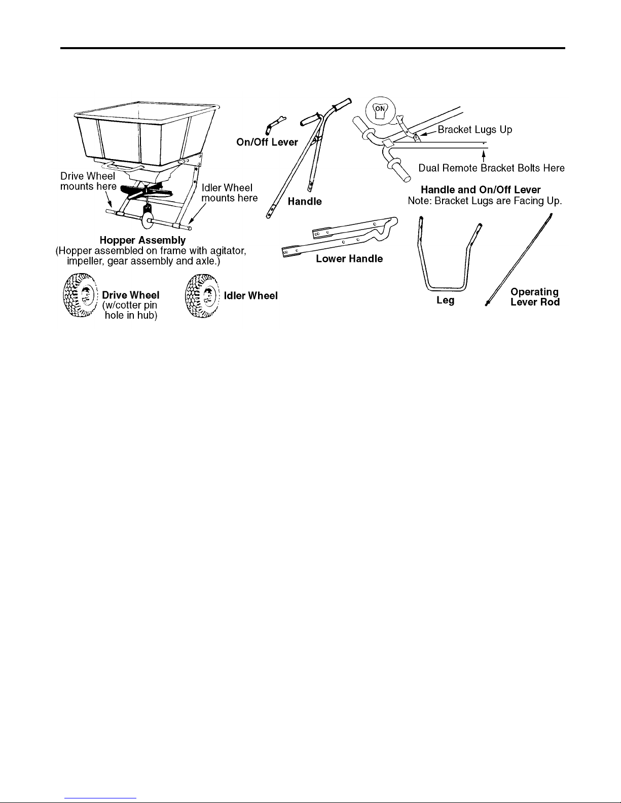
SECTION 1: ASSEMBLY INSTRUCTIONS
1. Remove the spreader components from the
carton. You should find all of the parts shown
above plus the Hardware Package.
The Hardware Package contains:
1 Cotter Pin, 3/16 x 1-3/4
1 Cotter Pin, 3/16 x 1-1/4
3 Spacer Washers, 3/4 I.D.
4 Cap Screws , 1/4-20 x 2-1/4, Hex Head
4 Machine Screws, 1/4-20 x 5/8, Phillips Head
5 Machine Screws, 1/4-20 x 1-1/2, Phillips Head
16 Flat Washers, 1/4
13 Hex Nuts, 1/4-20, Nylock
2 Clevis Pin, 1/4 x 1/2
2 Cotter Pin, 3/32 x 1/2
2 Cable Ties
1C-Clip
2. Place a spacer washer on each side of the axle
next to the axle bushing. Mount the drive wheel on
the side of the axle with the predrilled hole near
the axle bushing as shown in the illustration.
Attach by fastening on the inside of the wheel with
the 3/16 x1-3/4 cotter pin.
3. Mount the idler wheel on the other side of the axle.
Add a spacer washer and put the 3/16 x 1-1/4
cotter pin through the axle on the outside of the
wheel and spacer washer.
4. Mount the leg to the hopper assembly by fastening
with four 1/4-20 x 2-1/4 hex head cap screws and
four 1/4-20 locknuts. Use eight 1/4 flat washers
under the heads of the cap screws and under the
locknuts.
5. Mount the lower handle to the hopper assembly by
fastening with four 1/4-20 x 5/8 Phillips head
machine screws and four 1/4-20 locknuts.
6. Attach the handle (with the on/off bracket lugs
facing up) to the lower handle using four 1/4-20 x
1-1/2 Phillips head machine screws and four 1/420 locknuts. Use eight 1/4 flat washers under the
heads of the machine screws and under the
locknuts.
7. Fasten the on/off lever to the handle's bracket lugs
using the clevis pin in the bottom hole of the lever.
Insert the clevis pin from left to right, facing the
rear of the hopper. Lock with the 3/32 x 1/2 cotter
pin.
8. Attach the operating lever rod assembly to the
lever rod adjusting bracket at the bottom-rear of
the hopper. First insert clevis pin through hole in
lever rod adjusting bracket, than place flat washer
on to clevis pin. Insert clevis pin through top hole
in bellcrank pivot and secure with flat washer and
cotter pin.
9. Attach the operating lever rod to the on/off lever
by inserting the bent end of the rod into the top
hole of the lever from left to right and install the Cclip. Pull the on/off lever to the off position and set
the main slide plate to the fully closed position by
adjusting the 5/16 hex nuts on the bottom of the
operating lever rod.
10. Attach the dual remote bracket to the lower right
side of the handle using a 1/4-20 x 1-1/2 Phillips
head machine screw and a 1/4-20 locknut.
11. Insert the screen into the hopper.
2
Page 3
SECTION 2: SPREADER CALIBRATION
Two Items must be considered when calibrating a spreader. The first is the
pattern the product makes as It strikes the ground a fter being thrown out by th e spreader's impeller. Th ere are many factors whic h
affect the distribution p attern of a rotary s preader and so me of them relate di rectly to the produc t. For this reas on, we recommen d
that the spreader be c al ibra ted separately for every pro duc t to be applied. Spreader c ali bration should be chec ked at least once
a month, or more often when the spreader is used frequently.
The second item is the
tant because over-application can be costly and may cause plant injury, while under-application will reduce the effectiveness of
the product.
A. CHECKING THE SPREADER DISCHARGE HOLES:
Check the spreader discharge holes with the
operating lever in the closed position. If the discharge
holes are not fully closed, thread the upper nut on the
operating lever rod further up the rod. Tighten the
lower locknut and recheck. Repeat this procedure until
the holes ar e fully closed.
B. TO ACHIEVE A UNIFORM DISTRIBUTION PATTERN:
The accurate method for checking pattern uniformity
is to lay out shallow boxes or pans in a row on a line
perpendicular to the direction of spreader travel.
Eleven box es or pa ns , t wo i n ch es hi g h p l ac ed on on efoot centers will provide accurate calibration. To
conduct the test, begin with the remote and third hole
slide plates completely open and set the calibrating
slide at the suggested approximate setting. Make
three passes over the boxes, pushing the spreader in
the same direction each time. The product caught in
each box is then evaluated to determine the
distribution pattern. Weighing the product in each box
Is the most accurate, but a simpler method Is to pour
the contents of each box into a separate small vial or
bottle. Then set he eleven vials or bottles side-by-side
in order. This makes the pattern variation quite visible.
• To reduce the am ount of discharge to the ri ght side
(operator's right) partially close the remote slide plate
using the remote cable lever and repeat the test until
the distribution pattern is uniform.
• To reduce the amount of discharge to the left side
(operator's left) loosen the knob and partially close
the third hole slide plate and repeat the test until the
distribution pattern is uniform.
C. TO ACHIEVE THE CORRECT APPLICATION RATE:
The approximate spreader settings printed on the
product lab el should on ly be use d as the ini tial setti ng
for calibration. Set the calibrating slide at this
approximate setting. Using the collection boxes or
pans, make a single pass over them to determine the
effective pattern width. The effective pattern width is
twice (2x) the distance to the point where the rate
drops by one-half the average rate at the center.
Example: If the product In the vials from the center
boxes averages two inches in depth, count out to the
vial which has one inch of product. If this is the fifth
vial from the center and the boxes were on one-foot
centers, the effective pattern width is ten feet (2 x 5
ft.).
Knowing the effective pattern width (ten feet),
measure out a lineal distance to equal 1,000 sq. ft. (10
ft. x 100 ft. = 1,000 sq. ft.). Weigh 20 Ibs. of product
and place it i n the sp reader hoppe r and spr ead it over
the distance necessary to equal 1,000 sq. ft. (100 ft.).
Then weigh the product left in the hopper and subtract
this amount from the amount with which you started.
The result is the application rate for this product in
pounds per 1,000 sq. ft. that your spreader is currently
adjusted to disperse. Adjust the calibrating slide as
needed and repeat this procedure until the correct
product application rate
, that is the amount of prod uc t ap pl ied pe r th ous an d s qu are fee t. Th is is i mpor-
D. TO USE THE CALIBRATION GAUGES:
E. SPREADER OPERATION:
1. Always push the spreader; do not pull.
2. Push the spreader at a consistent speed (approximately
3. Always close the operating lever before filling the
4. Be sure the screen is in place to prevent lumps or paper
5. Always start moving forward before opening the
6. Hold the handle at a height that will keep the impeller
7. Empty the spreader after each use . Wash the spreader
8. Lubricate all linkages with spray lubricant. Grease the
distribution pattern
application rate is achieved.
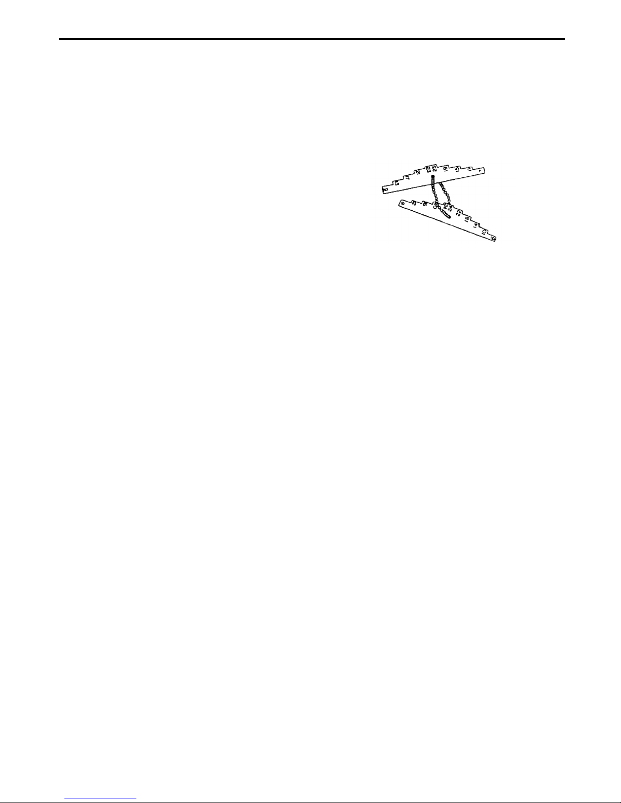
The calibration gauges provide a series of “steps”,
numbered i n 1/32-inch in crements, th at will allow y ou
to “fine-tune” the spreader. Once you have calibrated
your spreader for the product chosen, open the
operating lever and insert the calibration gauges until
you determine which step fits tightly into one of the
open holes in the hopper bottom. Record that step
number for future reference when using that product.
You may choose to set other spreaders for application
of the same product by adjusting the main slide plate
to that calibration gauge step. This will provide
consistent settings for all of your spreaders. To
recalibrate your spreader after a period of use, adjust
the calibrating slide to the “S” position. Open the
operating lever and insert the even-numbered
calibration gauge into one of the open holes in the
hopper bottom. Close the operating lever and let the
main slide plate on the underside of the hopper make
contact with the number ten step on the calibration
gauge. Move the calibrating slide back toward the “A”
position until the bottom of the slide makes contact
with the calibrating rod. If your spreader is properly
adjusted, the calibrating window should be pointing at
setting “D” on the top of the calibrating slide. To
correct a variance, adjust the calibrating window by
loosening the machine screws which hold it.
3 m.p.h. is recommended).
hopper.
scraps from plugging the holes in the hopper bottom.
operating lever ; close the oper ating lever bef ore forward
motion is stopped.
level.
thoroughly and al low it to dry. Keep the impell er clean.
gears with general purpose gun grease.
of the spreader. That is, the
3
Page 4
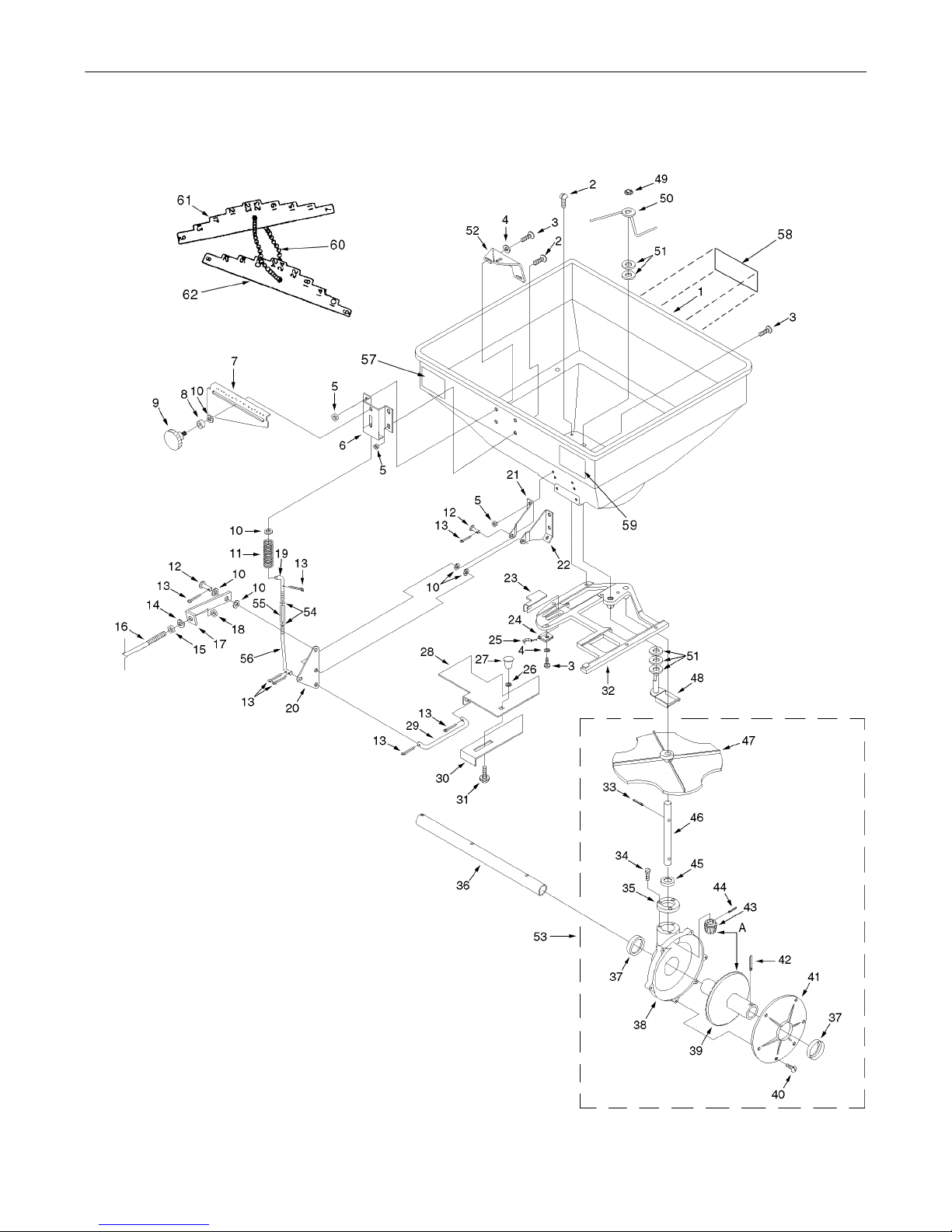
GEAR SET AND CONTROLS
4
Page 5

GEAR SET AND CONTROLS
Ref.
No. Part No. Description Qty.
1 01001003 Hopper 1 33 00060069 Roll Pin, 1/8 x 7/8, SS 1
2 00030423 Machine Screw, #10-24 x 1/2, SS 8 34 00030415 Screw, #10 x 5/8 T-A Hex Slot Hd., SS 3
3 00070028 Machine Screw, #10-24 x 5/8, SS 9 35 00030593 Cap, Gear Set 1
4 00030426 Flat Washer, #10, SS 3 36 00030391 Spreader Axle, SS 1
5 00070027 Hex Nut, #10-24 Nylock, SS 10 37 00030385 Seal, Housing and Cover 2
6 00030400 Bracket, Spring and Rod Guide, SS 1 38 00030591 Housing, Gear Set 1
7 00030406 Bracket, Calibrating Slide, SS 1 39 00030594 Gear 1
8 00018615 Spacer, Nylon .500 x .257 x .500 1 40 01000129 Screw, #6 x 5/8 T-A Pan Hd. Phil., SS 6
9 00018614 Knob, Calibrating Slide 1 41 00030592 Cover, Gear Set 1
10 00060033 Flat Washer, 1/4 SS 6 42 00060019 Roll Pin, 5/32 x 1-1/4, SS 1
1 1 00030433 Calibrating Spring, SS 1 43 00030595 Pinion Gear 1
12 00060031 Clevis Pin, 1/4 x 1/2, SS 2 44 00060022 Roll Pin, 1/8 x 5/8, SS 1
13 00060032 Cotter Pin, 3/32 x 1/2, SS 7 45 00030384 Seal, Gear Set Cap 1
14 00060073 Lock Washer, 5/16, SS 1 46 00030403 Impeller Shaft, SS 1
15 00060071 Hex Nut, 5/16-18, SS 1 47 00030317 Impeller 1
16 00030408 Lever Rod, SS 1 48 00030322 Agitator Cam, SS 1
17 00030398 Bracket, Lever Rod Adjusting, SS 1 49 00060050 Spring Clip 1
18 00060072 Hex Nut, 5/16-18 Nylock, SS 1 50 00060049 Agitator Arm 1
19 00030581 Calibrating Rod, SS 1 51 00005530 Plastic Washer 5
20 00030397 Bellcrank Pivot, SS 1 52 00030393 Calibrating Window 1
21 00030396 Bellcrank Pivot Mount, LH, SS 1 53 01002280 Kit, Impeller and Gear Set
22 00030395 Bellcrank Pivot Mount, RH, SS 1 54 00030626 Nut, 1/4”-28 SS 2
23 00030392 Remote Slide Plate, SS 1 55 00030550 Calibrating Rod Adjuster 1
24 00030424 Conduit Clip 1 56 00030580 Lower Calibrating Rod, SS 1
25 00030444 Cable, Remote Control 1 57 00090006 “USA” Decal 1
26 00018628 Flat Washer, 1/4, Nylon 1 58 01002102 MTD HWSS 100 Decal 1
27 00030427 Knob, Third Hole Slide Plate 1 59 01002182 100 lb. Capacity Decal 1
28 00030407 Main Slide Plate, SS 1 60 00009941 Chain 1
29 00030404 Linkage Rod, Slide Plate, SS 1 61 01002281 Calibration Gauge-Odd 1
30 00030399 Slide Plate, Third Hole, SS 1 62 01002282 Calibration Gauge-Even 1
31 00030428 Carriage Bolt, #10-24 x 3/8, SS 1
32 01002126 Guide, Shut Off Plate 1
Ref.
No. Part No. Description Qty.
5
Page 6
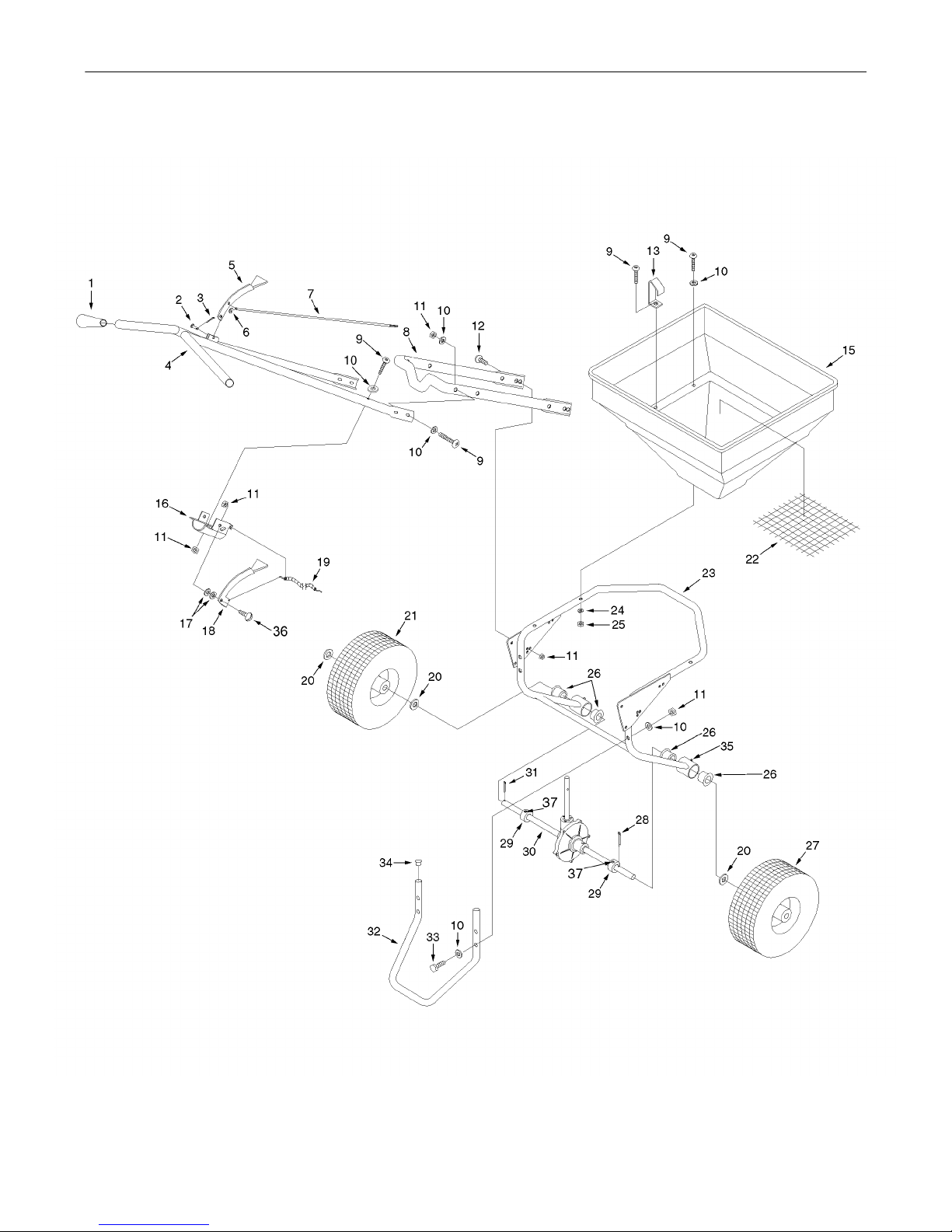
FRAME
6
Page 7

FRAME
Ref.
No. Part No. Description Qty.
1 000 304 46 Handle Grip 2 20 00060017 Spacer Washer, SS 7
2 00060031 Clevis Pin, 1/4 x 1/2, SS 1 21 00019790 Idler Wheel, Composite 1
3 00060032 Cotter Pin, 3/32 x 1/2, SS 1 22 00030412 Hopper Screen 1
4 00030413 Upper Handle, SS 1 23 00030500 Frame 1
5 00060034 Operating Lever, SS and Rubber
Knob
6 00010171 C-Clip 1 25 00060059 Hex Nut, 1/4-20, SS 4
7 00030408 Lever Rod, SS 1 26 00018963 Axle Bushing, Composite 4
8 00030436 Lower Handle, SS 1 27 00018901 Drive Wheel, Composite 1
9 00060047 Machine Screw, 1/4-20 x 1-1/2, SS 9 28 00060012 Cotter Pin, 3/16 x 1-3/4, SS 2
10 00060033 Flat Washer, 1/4, SS 19 29 00020019 Shaft Collar, SS 2
11 00060036 Hex Nut, 1/4-20 Nylock, SS 14 30 00030391 Spreader Axle, SS 1
12 00070029 Machine Screw, 1/4-20 x 5/8, SS 4 31 NA NA NA
13 00060046 Screen Clip, SS 2 32 00030438 Leg, SS 1
15 01001003 Hopper 1 33 00020962 Cap Screw, 1/4-20 x 2-1/4, SS 4
16 00030418 Bracket, Dual Remote, SS 1 34 00020913 Plastic Plug 2
17 00018628 Flat Washer, 1/4, Nylon 2 35 00060078 Grease Fitting,1/4-28 Straight 2
18 00030416 Remote Cable Lever, SS and Rub-
ber Knob
19 00030444 Cable, Remote Control 1 37 00010985 Set Screw 2
Ref.
No. Part No. Description Qty.
1 24 00060058 Lock Washer, 1/4, SS 4
36 00060057 Pan Hd. Mach. Scr. 1/4-20 x 7/8 1
1
7
Page 8
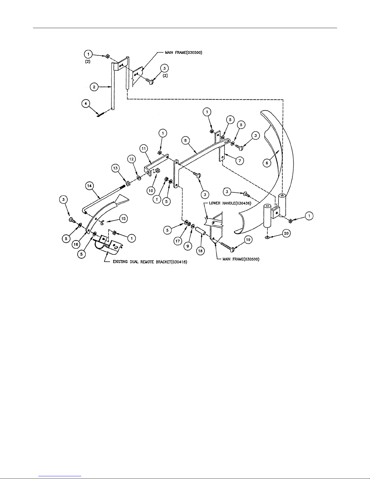
Deflector Kit
8
Page 9

Deflector Kit
Ref.
No. Part No. Description Qty.
1 00060036 Hex Nut, 1/4-20 Nylock SS 7 11 00030502 Deflector Adjusting Bracket 1
2 00030505 Deflector Mount Assembly 1 12 00060073 Lockwasher, 5/16 SS 1
00060057 Pan Hd. Mach. Scr. 1/4-20 x 7/8 6
3
4 00061052 Cotter Pin, 1/8 x 1" SS 1 14 00030508 Deflector Control Rod 1
5 00018628 Flatwasher, 1/4 Nylon 6 15 00010171 C-Clip Retainer 1
6 00061066 Deflector Tube 1 16 00060034 Operating Lever and Rubber Han-
7 00035030 Offset Bracket 1 17 00060059 Hex Nut, 1/4-20 SS 1
8 00030509 Deflector Lift Arm 1 18 00030503 Deflector Arm Mounting Spacer 1
9 00060033 Flatwasher, 1/4 SS 1 19 00060029 Machine Screw, 1/4-20 x 2 SS 1
10 00060072 Hex Nut, 5/16-18 Nylock SS 1 20 00061053 Flatwasher, 3/8 SS 1
MARK II DEFLECTOR KIT
INSTRUCTIONS
#01004434
1. Install the deflecto r mount (Ref.2) to the inside o f
the main frame on the right hand side using 2bolts(Ref.,3)
& 2-nuts(Ref.1) as shown on page 2.
2. Slide deflector tu be (Ref.6) & flat wash er (Ref.20)
on to the deflector mount ( Ref.2) insert cotter pin
(Ref.4) shown on page 2. Deflector tube (Ref.6)
must slide freely up & down deflector mount
(Ref.2).
3. Mount offset bracket (Ref.7) to deflector tube
(Ref.6) using 1-bolt (Ref.3) & 1-nut (Ref.1) as
shown on page 2.
4. Mount spacer (Ref.18) to the inside of the main
frame on the right hand side under, the lower
handle mount hole using 1-bolt (Ref.19),
flatwasher (Ref-9) 1-nut (Ref.17) & tighten, place
the deflector lift arm (Ref.8) between 2-nylon
washers (Ref.5) & with 1-nut (Ref .1) fasten so tha t
the lift arm will move firm but freely.
5. Connect the deflector lift arm (Ref.8) to the of fset
bracket (Ref.7) using 1-bolt (Ref.3), 2-nylon
Ref.
No. Part No. Description Qty.
13 00060071 Hex Nut, 5/16-18, SS 1
dle
washers (Ref.6) & 1-mut (Ref.1) as shown on
page 2, fasten so that bo lt slide freely in the s lot of
the lift arm.
6. Mount the deflector adjusting bracket (Ref.11) to
the deflector lift arm (Ref.8 ) with 1-bolt (Ref.-.3) &
1-nut (Ref.1) fasten so that the adjusting bracket
will move firm but freely-
7. Install the operator lever (Ref.16) to the existing
dual remote bracket as sho wn on page 2, usin g 1bolt (Ref.3), 2--nylon washers (Ref.5) & 1-nut
(Ref.1) so that the lever will move firm but freely.
8. Mount the deflector control rod (Ref.14) to the
deflector adjusting bracket (Ref.11) using 1-nut
(Ref.13), 1-lockwasher (Ref.12) & 1-locknut
(Ref.10) as shown on page 2.
9. Slide the deflector contr ol rod (Ref.14) through the
hole in the operato r lever (Reil.16) & secure with
retainer clip (Ref.15).
10. Adjust nut (Ref.1 3) & locknut (Ref.10) so tha t the
deflector tube (Ref.6) moves to the top of the
deflector mount (Ref.2) when the operator lever
lightly snaps over center of it's pivot point.
1
9
Page 10

EQUIPMENT ONE-YEAR LIMITED WARRANTY
This warranty is specific to the product manual it is attached to.
For a complete list of products and warranties contact your MTD Pro dealer.
Proper maintains of your MTD Pro equipment is the owne r’s responsibility.
manual for correct lub r ic ant s a nd m ai ntenance schedule. You r MTD Pro dealer carrie s a com pl ete line of quality lu bri cants and filters for your equipment’s engine, transmission, chassis and attachments.
1. What Is Covered By This Warranty.
MTD Pro equipment for one ye ar from the date of purchase fo r the first user purchaser. MTD Pro will replace or repai r
any part or parts without charge thro ugh you r auth ori zed MTD Pro d eal er. Batte rie s, be lts and tires will be co ve red fo r
a period of ninety (90) days from date of purchase. Engine warranties beyond listed coverage, if available, is handled
directly with the engine manufacturer.
2. What Is Not Covered By This Warranty.
cants, filters (oil, fuel, air and hydraulic), cleaning, tune-ups, brake or clutch inspection, adjustments made as part of
normal maintenance, bla de sharpeni ng, setup and normal we ar. (b) incident al costs su ch as transp orting equi pment to
and from the dealer, telephone charges or renting a product temporarily to replace a warranted product. (c) damage
caused by use of the equipment for purposes other than those for which it was designed; (d) damage caused by accident or disasters such as fire, flood, wind and lightning; (e) damage caused by unauthorized attachments or modification; or (f) any other abuse or misuse of the equipment.
3. EXCLUSIVE WARRANTY.
RANTIES OR REMEDIES, WHETHER WRITTEN, ORAL OR IMPLIED. ANY AND ALL IMPLIED WARRANTIES OF
MERCHANTABILITY, FITNESS FOR A PARTICULAR PURPOSE, COURSE OF DEALING OR USAGE OF TRADE
ARE HEREBY EXPRESSLY DISCLAIMED AND EXCLUDED.
4. LIMITATION OF REMEDIES.
PLICABLE LAW, SHALL MTD Pro BE LIABLE FOR ANY LOSS OR DAMAGE, DIRECT OR INDIRECT, SPECIAL, INCIDENTAL OR CONSEQUENTIAL ARISING OUT OF THE USE OF OR INABILITY TO USE THIS EQUIPMENT
INCLUDING BUT NOT LIMITED TO ANY CLAIM FOR LOSS OF PROFITS, LOSS OF SAVINGS OR REVENUE, LO SS
OF USE OF THE EQUIPMENT OR ANY ASSOCIATED EQUIPMENT, FACILITIES OR SERVICE, DOWNTIME, THE
CLAIMS OR COSTS OF THIRD PARTIES INCLUDING CUSTOMERS, AND INJURY TO PROPERTY.
Some states do no t al lo w li mit ations on how long an im pl ied w arr anty l as t s or t he exclusion or lim ita tio n of incidental or
consequential damages, so the above limitations or exclusion may not apply to you. This warranty gives you specific
legal rights, and you may also have other rights which vary from state to state.
THE FOREGOING WARRANTY IS EXCLUSIVE AND IN LIEU OF ALL OTHER WAR-
UNDER NO CIRCUMSTANCES, EXCEPT TO THE EXTENT PROHIBITED BY AP-
This limited warranty covers any defect in materials or workmanship in your
MTD Pro does not warrant (a) routine maintenance items such as lubri-
Follow the instructions in your owner’s
5. Future Changes.
ment or any compon ent pa rt or part s there of withou t incu rrin g the o bligat ions t o mak e such c hanges or mo dif icatio ns in
present equipment.
6. How to Obtain Service:
vice or replacement parts. If you need further assistance in finding an authorized MTD Pro servicing dealer, contact:
FORM NO. 01002123 Rev. 99-1
MTD Pro reserves t he right to reserve, c han ge or mo dify the constructio n a nd design of its Equip-
Contact the authori zed MTD Pro deale r at the point o f origi nal reta il purc hase to obtain ser-
MTD Pro
P.O. Box 361131
Cleveland, Ohio 44136
 Loading...