

Page 1
.50
ASSEMBLY
OPERATION
MAINTENANCE
PARTS LIST
IMPORTANT;
Read Safety Rules
and Instructions
PRINTED IN U.S.A.
MODEL NUMBERS
190-469A
TMO-33849A
36”
SNOW THROWER
ATTACHMENT
FORM No. 770-0106
(Rev. 8/79)
Page 2

LIMITED WARRANTY
For one year from the date of original retail purchase, MTD PRODUCTS INC will either
repair or replace, at its option, free of charge, F.O.B. factory or authorized service firm,
any part or parts found to be defective in material or workmanship. Transportation charges
under this warranty must be paid by the purchaser unless return is requested by
MTD PRODUCTS INC.
This warranty will not apply to any part which has become inoperative due to misuse,
excessive use, accident, neglect, improper maintenance, alterations, or unless the unit
has been operated and maintained in accordance with the instructions furnished. This
warranty does not apply to the engine, motor, battery, battery charger or component parts
thereof. Please refer to the applicable manufacturer’s warranty on these items.
This warranty will not apply where the unit has been used commercially.
Warranty service is available through your local authorized service dealer or distributor. If
you do not know the dealer or distributor in your area, please write to the Customer Service
Department of MTD.
The return of a complete unit will not be accepted by the factory unless prior written
permission has been extended by MTD.
This warranty gives you specific legal rights. You may also have other rights which vary
from state to state.
Page 3

IMPORTANT
Safe Operation Practices for Snow Throwers
TRAINING
1. Read the owner's guide instruction manual careful
ly. Be thoroughly familiar with the controls and
proper use of the equipment. Know how to stop the
unit and disengage the controls quickly.
2. Never allow children to operate equipment. Never
allow adults to operate equipment without proper
instruction.
3. Keep the area of operation clear of all persons, es
pecially small children and pets.
4. Exercise caution to avoid slipping or falling, es
pecially when operating in reverse.
PREPARATION
1. Thoroughly inspect the area where the equipment
is to be used and remove all door mats, sleds,
boards, wires and other foreign objects.
2. Disengage all clutches and shift into neutral before
starting engine or motor.
3. Do not operate equipment without wearing ade
quate winter outer garments. Wear footwear which
will improve footing on slippery surfaces.
4. Handle fuel with care, it is highly flamamble.
(A) Use approved fuel container.
(B) Never add fuel to a running engine or hot en
gine.
(C) Fill fuel tank outdoors with extreme care. Never
fill fuel tank indoors.
(D) Replace gasoline cap securely and wipe up
spilled fuel.
(E) Open doors if engine is run in the garage—ex
haust fumes are dangerous.
5. Adjust coilector housing height to clear gravel or
crushed rock surface.
6. Never attempt to make any adjustments while en
gine or motor is running (except where specifically
recommended by manufacturer).
7. Never operate the snow thrower without good vis
ibility or light.
8. Let engine and machine adjust to outdoor tempera
tures before starting to clear snow.
OPERATION
1. Do not put hands or feet near rotating parts. Keep
clear of discharge opening at all times.
2. Exercise extreme caution when operating on or
crossing a gravel drive, walks, or roads. Stay alert
for hidden hazards and traffic. Do not carry pas
sengers.
3. After striking a foreign object, stop the engine
(motor), remove wire from spark plug, thorough
ly inspect the snow thrower for any damage, and
repair the damage before restarting and operat
ing the snow thrower.
4. If the unit should start to vibrate abnormally, stop
the engine (motor) and check immediately for the
cause. Vibration is generally a warning of trouble.
5. Stop engine (motor) whenever you leave the oper
ating position, before unclogging the collector/
impeller housing or discharge guide, and making
any repairs, adjustments, or inspections.
6. Take ail possible precaution when leaving the ve
hicle unattended, disengage the power take-off,
lower the attachment, shift into neutral, set the
parking brake, stop the engine, remove the key.
/. When cleaning, repairing, or inspecting make cer
tain collector/impeller, and all moving parts have
stopped. Disconnect spark plug wire and keep
wire away from plug to prevent accidental start
ing. Disconnect cord on electric motors.
8. Do not run engine indoors, exhaust fumes are
dangerous.
9. Do not clear snow across the face of slopes. Ex
ercise extreme caution when changing direction
on slopes. Do not attempt to clear steep slopes.
10. Never operate snow thrower without guards,
plates, or other safety protective devices in place.
n. Never operate snow thrower near glass enclosure,
automobiles, window wells, drop-offs, etc., with
out proper adjustment of snow discharge angle.
Keep children and pets away.
12. Do not overload machine capacity by attempting
to clear snow at too fast a rate.
13. Never operate machine at high transport speeds
on slippery surfaces. Use care when backing.
14. Never direct discharge at bystanders or allow any
one in front of unit.
15. Disengage power to collector/impeller when
transporting or not in use.
16. Only use attachments and accessories approved by
manufacturer of snow thrower (such as wheel
weights, counter weights, cabs, etc.).
MAINTENANCE AND STORAGE
1. Check shear bolts, engine mounting bolts, etc. at
frequent intervals for proper tightness to be sure
equipment is in safe working condition.
2. Never store machine with fuel in the fuel tank in
side a building where open flame or spark are pres
ent. Allow engine to cool before storing in any
enclosure.
3. Always refer to owner's guide instructions for im
portant details if snow thrower is to be stored for
an extended period.
4. Ron machine a few minutes after throwing snow
to prevent freeze up of collector/impeller.
Page 4
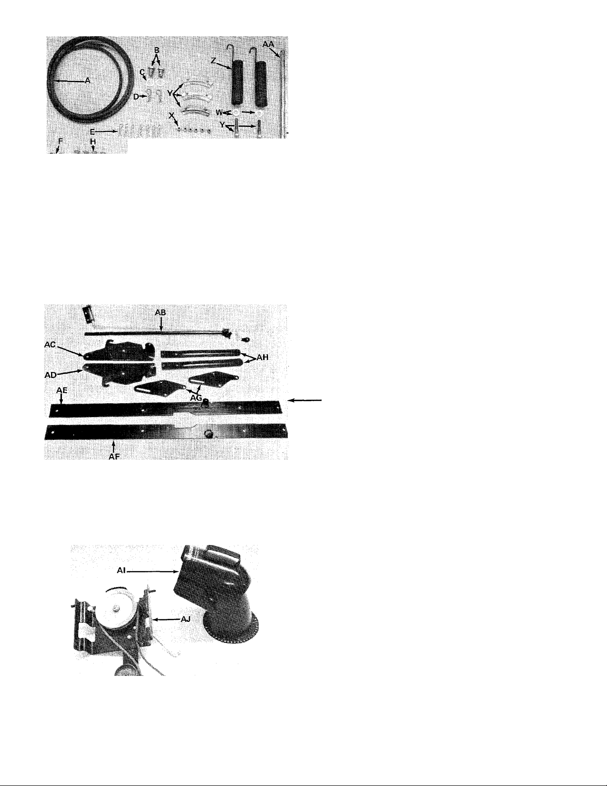
LIST OF CONTENTS IN HARDWARE PACK
SEE FIGURE 1
+
G
FIGURE 1
A (1)
B (2)
C (2)
D (2)
E
— F
0
1
J
\
/
N
I
/
R*"
t
p
wm
S—
T
Q-'
G
H (4)
I
J
K (2)
L (2)
M (2)
N (2)
0 (2)
P (2)
Q (8)
R-(2)
S (4)
T (4)
U (4)
V (2)
W (2)
X (6)
Y (3)
Z (2)
AA (1)
"V"-Belt 1/2" X 85" long
Clevis Pins
Flat Washers
Hair Pin Cotters
Hair Pin Cotters
(7)
Hex Top Lock Nut 5/16-18 Thread
(2)
Flat Washers
(2)
Carriage Bolts 5/16-18 x 5/8" long
Lock Washers 5/16" I.D.
(8)
Hex Nuts 5/16-18 Thread
(4)
Flat Washers
Hex Bolts 5/16-18 x 1.00" long
Hex Bolts 5/16-18 x .75" long
Hex Bolts 5/16-18 x 1.25" long
Hex Bolts 3/8-16 X 1.00" long
Lock Washers 3/8" I.D.
Hex Nuts 5/16-18 Thread
External Lock Washers 5/16" I.D.
Lock Washers 1/2" I.D.
Hex Nuts 1/2-13 Thread
Hex Bolts 1/2-13 X 1.25" long
Hex Bolts 5/16-18 x 2.00" long
Flat Washers
Hex Center Lock Nuts 1/4-20 Thread
Chute Flange Keeper Ass'yHelper Springs
Lift Handle Shaft
FIGURE 2
FIGURE 3
LIST OF LOOSE PARTS IN CARTON
SEE FIGURES 2 and 3.
AB (1)
AC (1)
AD (1)
AE
AF
AG (2)
AH (2)
Preassembled Chute Crank & Support
Channel Supporting Bracket - L.H.
Channel Supporting Bracket - R.H.
Linkage Arm Assembly - L.H.
(1)
Linkage Arm Assembly - R.H.
(1)
Linkage Brackets
Drift Cutters
_AI (1} Preassembled Chute Assembly
AJ (1) Preassembled Idler Assembly
TOOLS REQUIRED
1. Adjustable Wrench
2. A strong piece of wire
3. A screwdriver
4. A pair of pliers
5. A 7/16" Open End Wrench
6. A 1/2" Open End Wrench
7. A 9/16" Open End Wrench
8. A 3/4" Open End Wrench
Page 5
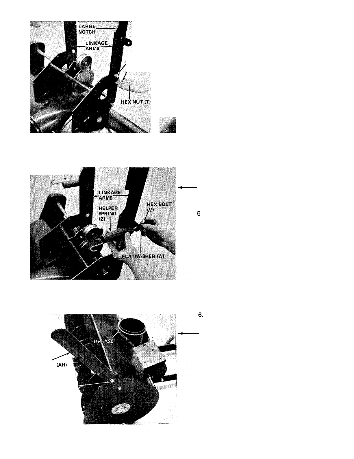
FIGURE 4
HEX BOLT (U)
LOCKWASHER (S)
ASSEMBLY INSTRUCTIONS
1. Remove the snow thrower, all loose parts and
hardware package from the carton.
2. Tip the snow thrower forward, so that the augers
are face down.
■ 3. Assemble the linkage arms (Ref. AE & AF) to the
housing assembly as shown in figure 4. Be sure
the linkage arms have the large notch up. Secure
with four hex bolts (U) 1/2-13 x 1.25" Lg., four
hex nuts (T) and lockwashers (S) provided.
HELPER bPRING (Z)
FIGURES
4. Place helper spring (Z) in position on linkage arm
assemblies. Secure with flat washers (W) and hex
bolts (V) provided in hardware pack. See figure
5. Thread bolt approximately one inch into the
spring insert. Adjustment is made in step number
26.
Tip the snow thrower back in normal position so
that is rests on linkage arms.
Assemble the drift cutters (AH) to the snow
thrower housing with four carriage bolts (H),
lockwashers (I) and hex nuts (J). See figure 6.
Heads of carriage bolts assemble from the inside
of housing.
DRIFT
CUTTER
CARRIAGE BOLT
(H)
LOCK WASHER (I)
HEX NUT (J)
FIGURES
Page 6
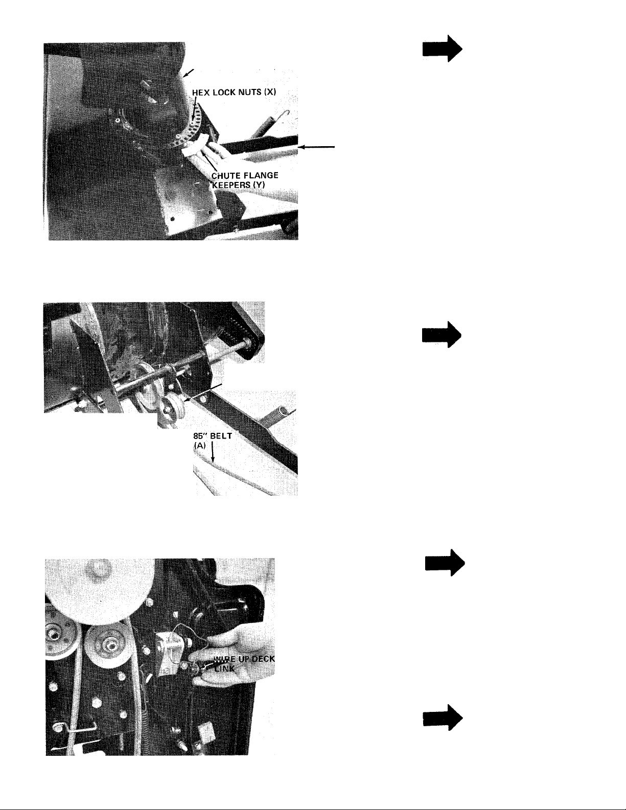
FIGURE 7
CHUTE ASSEMBLY (Al)
NOTE
Before setting the chute assembly on
the spiral housing assembly, grease the
housing for ease of operation. See
figure 7.
7. Assemble the chute assembly (Al) to the housing
using three chute flange keepers (Y) and six hex
lock nuts (X). See figure 7.
■8. Place the 85" belt (A) in position on the idler of
the snow thrower as shown in figure 8.
NOTE
FIGURES
IDLER PULLEY
The idler bracket has three holes for
belt tension adjustment. Normally, the
idler pulley is assembled in the center
hole. If the belt is too tight to
assemble, the idler pulley may be
moved to the top hole.
PREPARING THE LAWN
TRACTOR FOR ASSEMBLY
OF SNOW THROWER
1. Remove the gas cap and place a piece of plastic
film on the gas cap to prevent gas from leaking out
of the tank.
NOTE
If unit is electric start remove the
battery.
2. Remove the spark plug wire from spark plug and
grounrd.
3. Remove the mowing deck.
4. With a piece of wire hold the front left hand deck
hanger out of the way. See figure 9.
FIGURE 9
NOTE
This hanger bracket is straight.
Page 7

FIGURE 10
NOTE
After removing the deck, check the
deck links. The weld pins should be
outboard. If not, change them. It is
easier to change deck links by re
moving the transmission cover and
knob. After changing deck jinks,
reassemble the transmission cover and
knob.
Remove the second bolt on the running boards as
shown in figure 10. (Right and left hand sides).
Replace the bolts with hex bolts (N) 5/16-18 x
1.25" Lg. provided with snow thrower. Fasten
with 5/16-18" nut (Q) and lock washer (I).
Tighten with wrench.
FIGURE 11
7. Tip the lawn tractor up on its rear wheels so that
the unit rests on the back on the seat.
Remove the belt keeper and shoulder bolt at
engine pulley (if these were replaced when deck
was removed).
9. Assemble the channel supporting brackets right
and left hand to lawn tractor. See figures 12 and
13.
10. Hook thp'^!^ of channel supporting bracket right ^
hand''fAD) of oki^ pedal mounting
bracket. See figure 12.
11. Place flanged edge of channel support bracket
over hex bolt (N) (which you assembled in step 6).
Secure with lock washer (I) and hex nut (Q). See
figure 13.
FIGURE 12
Page 8

HEX BOLT
(N)
FIGURE 13
1 V
u>vin DIM COTTFR^i^
.12. Pre-assemble the linkage bracket (AG) to the
idler assembly (AJ), as shown in figure 14.
Secure with hair pin cotter (E). NOTE: Slot in
linkage bracket goes to the rear.
LINKAlU EiBACKl I -tO'
FIGURE 14
FLARVASHFI.:-;
CONTROL ROD
(K<^
HAIR PIN COTTERS (E)
IHp
■ 13. Assemble the other linkage bracket (AG) to the
other side of idler assembly (AJ). Secure with
hair pin cotter (E). Place flat washer (K) over
control rod. Next, place control rod up through
linkage bracket. Secure with another flat washer
(K) and hair pin cotter (E). See figure 15.
FIGURE 15
Page 9

FIGURE 16
BELT GUARD
IDLER PULLEY
14. Be sure belt on idler assembly is in position on
i
idler pulley between belt guard and weld pin as
shown in figure 16.
15. Place the idler assembly in position between
channel supporting brackets and start hex lock
nuts (F) and flat washers (G) over weld studs as
shown in figure 17.
FIGURE 17
16. Place lift handle links down through idler
assembly and secure to linkage brackets with
hair pin cotters (E). See figure 17.
17. Start hex bolts (O) and lock washers (P) through
center of channel support and idler assembly. See
figure 18.
18. Tighten nuts and bolts in steps 15 and 16
securely with wrenches.
FIGURE 18
Page 10

19. Slip the idler assembly belt over the engine pulley
as shown in figure 19.
NOTE
Be sure the belt runs between idler
pulley and guard as shown in figure 19.
20. Replace the engine pulley belt keeper and large
shoulder bolt. See figure 20.
FIGURE 20
21. Set the lawn tractor back down on all four wheels.
22. Roll the lawn tractor over the snow thrower and
attach the free end of the 85" belt to the pulley
on the idler assembly. Be sure to twist the belt so
that the top of belt coming off the idler goes
toward the left side of unit. See figure 8.
NOTE
If belt is installed incorrectly spirals
will run in reverse. Twist belt in other
direction to correct. Refer to step 22.
FIGURE 21
LINKAGE AFIM
23. Place the holes in the end of the linkage arms
in line with slot in the linkage brackets and
secure with lift handle shaft (AA) and hair pin
cotters (E). See figure 21. Lower the lift handle
on the lawn tractor to its lowest position.
NOTE
Linkage arms must be mounted on_the
outside of linkage brackets. Refer to
10
figure 21.
Page 11

FIGURE 22
24. With a piece of strong wire hook the end of
helper springs (Z) up into grille mount on lawn
tractor. See figure 22.
25. After springs are installed raise and lower the lift
handle on lawn tractor to be sure snow thrower
is properly hooked up.
26. Using a 1/2" wrench, tighten securely hex bolts
(V) which are threaded into the spring inserts.
Refer to step number 4.
27. Attach the pre-assembled chute crank and support
(AB) to the snow thrower housing. Secure the
support with two hex bolts (L), lock washers
(I) and hex nuts (Q). Secure the chute crank with
two hex bolts (M), lock washers (I) and hex nuts
(Q). See figure 23. Be sure teeth on chute crank
link up with holes in chute flange before
tightening bolts.
Remove the piece of plastic film from the gas cap.
Reinstall the battery and replace the spark plug
wire.
29. Check tire pressure. It may be necessary to put
more air into the front tires due to the weight of
the snow thrower.
FIGURE 23
11
Page 12

OPERATING INSTRUCTIONS
This snow thrower is capable of handling heavy
snow conditions. If given the opportunity to function
within reasonable requirements it should give many
years of service. Become fully familiar with all aspects
of both the lawn tractor and snow thrower prior to
its usage.
BEFORE PLACING SNOW THROWER INTO OPERATION
1. Check all nuts and bolts for correct tightness
and be sure that ail parts are properly assembled.
2. Test all controls for smooth operation.
A. Lift lever
B. Discharge chute control crank
C. Discharge chute and deflector
3. Starting and stopping snow thrower.
The snow thrower is driven by a V-belt driven from
the lawn tractor engine. It is operated through the
lift disengagement handle. Start lawn tractor engine
and run at full throttle. Slowly engage (push forward)
the lift handle.
To stop snow thrower operation, pull the lift handle
towards you and lock handle.
DISCHARGE CHUTE CONTROL CRANK
The discharge chute control crank is located on left
hand side of lawn tractor. Turn crank to the right to
direct snow to the right hand side. Turn it to the left
to direct snow to left hand side.
TO RAISE AND LOWER SNOW THROWER
Lift lever to raise and lower snow thrower is located
on the right hand side of lawn tractor. To raise snow
thrower pull back on lift lever until it reaches over
center stop. To lower snow thrower, push lift lever
forward slowly until snow thrower reaches gcound
level.
When snow thrower and lawn tractor
are not in use, lower snow thrower to
ground lever. This will prevent excess
weight on the front tires.
OPERATING ADJUSTMENTS
A
When making skid shoe or chute
- deflector adjustment, turn rider enengine off.
Upper Chute Deflector: The upper chute deflector
mounted on the top of the chute determines the
distance snow is thrown. Moving top of deflector
down decreases distance of throw and raising deflector
increases distance of throw. Operator must get off
lawn tractor to make this adjustment. Disengage
spirals (by raising snow thrower) before making this
adjustment.
SKID SHOE ADJUSTMENT (See Figure 24)
The skid shoes are mounted on each side of spiral
housing. These regulate the distance the shave plate
is raised above the plowing surface. When removing
snow from a gravel driveway or an uneven surface, it
is advisable to keep shave plate as high above the
surface as possible to prevent possible damage to
spiral.
CAUTION
PREPARATION
1. Check the lawn tractor and thrower to make
certain both are in good operating condition.
2. Fill gas tank out of doors and avoid spilling
gasoline over engine. Do not fill tank while
engine is running. Wipe up any spilled gas.
3. Do not remove any guards or covers while
operating lawn tractor and thrower.
Snow thrower chute has a discharge radius of 180
degrees. Adjust discharge by turning the chute crank.
SKID SHOE
12 FIGURE 24
Page 13

On blacktop or concrete surface, keep shave plate
as close to the surface as possible. Skid shoes can be
adjusted so that shave plate will rest directly on the
surface. Turning skid shoes around will allow even
wear on skid shoes.
Raise snow thrower off the ground and place a block
at each end of shave plate. Loosen 4 nuts securing
skid shoes to spiral housing (2 nuts on each side).
Move skid shoes up or down to desired position and
tighten nuts securely. Adjust both skid shoes to the
same height to keep spiral level. See figure 24.
OPERATION
The thrower controls are conveniently located at the
operator's position on the lawn tractor. By engaging
the lift handle to the spiral, snow is thrown through
chute by the motion of the spiral. Turning chute
crank directs snow discharge and deflector controls
distance snow is thrown.
A
If snow thrower becomes plugged with
snow, or jammed due to hitting a
foreign object, disengage snow thrower
immediately and stop lawn tractor
engine. Clear snow from chute if
plugged, before resuming operation.
CAUTION
OPERATING SPEED
The spiral speed is directly related to engine speed.
For maximum snow removal and discharge, maintain
high engine R.P.M. (full throttle). The lawn tractor's
forward speed is controlled by selecting one of the
forward speeds. It is advisable to operate the lawn
tractor at a slow ground speed (1st gear) for safe
and efficient snow removal.
DEEP OR DRIFTED SNOW
In deep, drifted, or banked snow, it will be nec
essary to use full throttle and first speed. Drive the
spiral into the snow, disengage clutch and allow spiral
to clear the snow. Repeat this method until a path is
cleared. On the second pass, overlap the first enough
to allow the spiral to handle the snow without repeated
clutching and declutching of the lawn tractor.
In extremely deep snow, raise thrower from the
ground, drive lawn tractor ahead in the deep snow to
remove top layers first. Do not drive lawn tractor into
snow bank where snow has not been removed to
ground level. Disengage lawn tractor clutch and allow
thrower to clear the snow. Reverse lawn tractor and
lower thrower to the ground. Drive lawn tractor
ahead and repeat process to remove balance of snow.
Working with repeated passes into and out of drifts
will eventually move even the deepest of snow piles.
NOTE
If spiral is jammed or bent from hit
ting a foreign object, stop lawn tractor
engine. Remove spark plug wire from
spark plug and then remove foreign
object from spiral. If spiral damage
is noted, repair prior to continuing
operation. Then replace spark plug
wire and resume operation.
SNOW CONDITIONS
Snow removal conditions vary greatly from light
fluffy snowfall to the wet heavy snow. Therefore,
operating instructions must be flexible to fit conditions
encountered. The operator must adapt the lawn
tractor and snow thrower to depth of snow, wind
direction, temperature, and surface conditions.
OPERATING TIPS
1. Whenever possible discharge snow down wind.
2. Do not attempt to remove ice or hard packed
frozen snow.
3. Always overlap each pass slightly to assure
conhplete snow removal.
4. A frozen or stuck spiral or chute must be broken
loose or thawed with care. When attempting to
loosen frozen or jammed spiral, shut off rider
engine and remove spark plug wire. Never attempt
to clear snow thrower at any time with lawn
tractor engine running.
USE OF TIRE CHAINS
Tire chains should always be used when extra
traction is needed. They add maneuverability in
13 handling snow removal jobs.
Page 14

LUBRICATION
1.
Spiral drive chain: Lubricate chain every 40
operating hours with No. 30 oil. It is important
that oil reaches inside each roller. Wipe off excess
oil from chain.
2.
Pivot and friction points: To maintain smooth
and free operation, apply a few drops of No. 30
oil as required to all pivot and friction points.
The spiral and idler pulley bearings are self-lubricating.
However, periodic lubrication with No. 30 oil will
lengthen service life.
SPIRAL DRIVE CHAIN ADJUSTMENT
Periodically check spiral drive belt to insure that it is
properly adjusted. It is important to maintain proper
belt adjustment to obtain maximum belt life.
If belt is stretched beyond idler take up, replace with
a new belt of the type specified in parts list.
Excessive slack in spiral drive chain due to normal
chain stretch can be removed by adjusting spiral
housing nuts.
TO ADJUST SPIRAL CHAIN:
1. Disengage snow thrower and loosen the mounting
nuts 2 or 3 complete turns.
2. Tighten the adjustment mounting nuts to tighten
chajn.
BELT TENSION ADJUSTMENT
The idler bracket has three holes for belt tension
adjustment. As the belt stretches from normal wear,
more belt tension may be required. Check the idler
spring for wear against the drive shaft at least once a
season. If the idler spring is rubbing against the drive
shaft, the belt has stretched and must be adjusted.
Remove the idler pulley from the bracket, and
reassemble in next lower hole on the bracket.
STORAGE
At the end of the snow season the following steps
are recommended:
1. Remove snow thrower assembly from lawn tractor
tractor.
2. Wash off any salt deposit which may have dried
on the thrower and housing. Paint or cover
exposed metal with a light coat of oil.
3. Lubricate thrower following lubricating in
structions for recommended lubricant. Thrower
drive chain must be oiled thoroughly to prevent
rust from forming. The preferred method is to
remove the chain and soak in oil for several hours
before reinstalling.
4. Store thrower in a dry place.
CAUTION
Do not over tighten chain. A correctly
adjusted chain will have a slight
amount of slack. An over tightened
chain will result in early failure of
chain.
3. Tighten mounting nuts to securechain adjustment.
Check chain clearance. It must clear chain guard
assembly. Test chain and repeat adjustment if
necessary until all excess slack is removed.
SHAVE PLATE AND SKID SHOES
Both the shave plate and skid shoes are subject to
wear and are designed to be easily replaced. Replace
before wear is excessive. Failure to do so will result
in damage to the spiral housing.
14
Page 15

NOTES
Page 16

190-469A
TM0-33849A
EXPLODED VIEW
16
IF YOU WRITE TO US ABOUT THIS ARTICLE
OR IF YOU ORDER REPLACEMENT PARTS AL
WAYS MENTION THIS MODEL & SERIAL NO
MODEL
Page 17

PARTS LIST FOR 190-469A and TMO-33849A 36" SNOW THROWER ATTACHMENT
REF.
NO.
PART
NO.
1 05023
715-0118
2
05375
3
4 712-0158
736-0105
5
736-0179
6
05225
7
710-0260
8
05140
9
712-0107
10
11 726-0111
05404
12
712-0267
14
736-0119
15
710-0260
16
736-0163
17
713-0177
18
713-0189
19
05379
20
715-0118
21
736-0119
22
712-0267
23
736-0105
24
712-0130
25
05244
26
712-0267
27
736-0119
28
741-0162
29
30
31
32
33
34
35
36
37
38
39
40
41
42
43
44
45
_
715-0118
713-0188
756-0192
750-0252
736-0235
736-0300
710-0427
738-0244
05401
720-0170
05403
05120
736-0117
720-0171
726-0100
46 05837
754-0236
47
713-0154
48
738-0140
49
05724
50
732-0383
51
COLOR
CODE
DESCRIPTION
Spiral Plate
Spring PinSpir. 5/16x1.75”
Lg.
Spiral Ass’y-
Hex Cent. L-Nut 5/16-18
Thd.*
Bell. Wash.
FI-Wash.
Top Chute Ass’yCar. Bolt5/16-18x.62” Lg.*
Chute Wing Ass’y.
Hex Cent. L-Nut V4-20 Thd.
Push Cap .188” Dia. Rod
Chute Ass’y.
NEW
PART
REF.
NO.
52 756-0217 FI. Idler with Flange
53
54
55 741-0174
56
57 736-0231 FI-Wash.
58 756-0215 5.50 O.D. X 5/8 Pulley
59 710-0198 Hex Sems Scr. 5/16-18 x .75”
60
61
62
63 736-0921 L-Wash. 1/2” Scr.*
64
65
PART
712^0130
NO.
COLOR
CODE
DESCRIPTION
Hex Ins. Jam Nut 3/8-16 Thd.
736-0119 L-Wash. 5/16” Scr.*
Self Aligning Brg.
710-0538 Hex Scr. 5/16-18 X.62” Lg.
716-0119 Snap Ring for .75 Dia. Shaft
710-0474
05432
Hex Scr. 1/2-13x1.25” Lg.*
Spiral Housing Ass’y.
712-0206 Hex Nut 1/2-13Thd.*
710-0260 Car. Bolt5/16-18X.62”Lg.*
66 712-0267 Hex Nut5/16-18Thd.*
Hex Nut 5/16-18 Thd.*
L-Wash. 5/16” Scr.*
Car. Bolt 5/16-18 X.62” Lg.*
FI-Wash.
Sprocket Hub Ass’y.—40
Teeth
#420 Chain X 1/2” Pitch—77
Links 74
Chain Guard Ass’y.
67
736-0119 L-Wash. 5/16” Scr.*
05378
68
Shave Plate
69 710-0389 Car. Bolt 3/8-16 X.75” Lg.*
05002
70
71 712-0798
Slide Shoe
Hex Nut 3/8-16
72 736-0105 Bell. Wash.
73
710-0538 Hex Scr. 5/16-18 X.62” Lg.
736-0227
FI-Wash.
75 741-0170 Flange Brg. with Flats
Spring Pin SfUr.—5/16 76 05360 Brg. Housing Ass’y.
L-Wash. 5/16” Scr.*
Hex Nut 5/16-18” Thd.*
77
710-0260 Car. Bolt5/16-18X.62”Lg.*
78 05139 Guide Blade
Bell. Wash. 79 736-0119 L-Wash. 5/16” Scr.*
Hex Ins. L-Nut 3/8-16” Thd. 80 712-0267
Bearing Housing
81 736-0119
Hex Nut 5/16-18 Thd.*
L-Wash. 5/16”.Scr.*
Hex Nut 5/16-18” Thd.* 82 712-0267 Hex Nut 5/16-18 Thd.*
L-Wash. 5/16” Scr.*
Self Aligning Brg. w/Set Scr. 84
Comes with Ref. No. 29
Spring Pin Spir.—5/16 X1.75
14 Teeth Sprocket Ass’y.
1.875” Dia. Flat Idler
Idler Spacer 89
FI-Wash. 90
FI-Wash.
Hex Scr. 3/8-16x2.00” Lg.* 92 715-0139
Drive Shaft
Crank Support Tubing Ass’y.
Hand Knob 5/16-18 Thd.
Chute Crank Brkt.
Chute Crank
FI-Wash.
Knob—Black 3/8” Dia. Hole
716-0121
83
85
736-0242
712-0267
Snap Ring fori .50” Dia. Shaft
Bell. Wash.
Hex Nut 5/16-18 Thd.*
86 714-0111 Cotter Pin 3/32x1.00” Lg.*
712-0267 Hex Nut 5/16-18 Thd.*
87
88 736-0119
710-0376
711-0584
05066 Joint Brkt. Ass’y.
91
L-Wash. 5/16” Scr.*
Hex Scr. 5/16-18 X1.00” Lg. *
Joint Block
Spring Pin Roll 3/16" X.81"
Lg.*
93 715-0103
Spring Pin Roll 1 /8 X .75”
Lg.*
94
710-0118
05402 Chute Brkt.
95
05118 Sprocket Shaft Ass’y.
96
97 05031
Hex Scr. 5/16-18 X.75” Lg.*
Chute Flange Keeper Ass’y.
Push Nut 3/8” Rod
N
Linkage Arm Ass’y.
98 738-0229
“V”-Belt 1/2” X 85” Lg.(Kevlar 99
Master Link for #420 Chain
Shoulder Scr.
Idler Brkt. Ass’y.
Extension Spring
100 05136
101
N X.565
102
I 103
736-0250
748-0193
05838
710-0347
Spiral Axle
FI-Wash.
Plastic Bushing
Spacer .3801.D. x .630 O.D.
Linkage Arm Ass’y.—R.H.
Hex Bolt 3/8-16 X 1.75" Lg.*
NEW
PART
N
‘For faster service obtain standard nuts, bolts and washers locally. If these items cannot be obtained locally, order by part
number and size as shown on parts list.
17
Page 18

190-469A
TMO-33849A
exploded view
18
Page 19

PARTS LIST FOR 190-469A and TMO-33849A 36" SNOW THROWER ATTACHMENT
REF.
NO.
. 3
PART
NO.
1 710-0528
2 736-0119
712-0267
4
712-0116
5 756-0218
6 754-0185
COLOR
CODE
DESCRIPTION
Hex Scr. 5/'16-18 x 1.25” Lg.*
L-Wash. 5/16” Scr.*
Hex Nut 5/16-18 Thd.*
Hex Ins. Jam Nut 3/8-24 Thd.
Flat Idler 3.25” O.D.
“V”-Belt 1/2 X 49” Lg.
NEW
PART
7 712-0242 He'x Jam Nut 5/8-11 Thd.
8 736-0158
9 756-0216
10
738-0129 Shoulder Screw
05644
11
L-Wash.
6.50” O.D. X 5/8 Pulley
Channel Supporting
Brkt.-R.H.
12 05835
05838
13
14 714-0101
736-0192
15
710-0528
16
736-0169
17
712-0798
18
08253
19
736-0119
20
712-0267
21
22 05406
714-0388
23
Linkage Brkt.
Linkage Arm Ass’y.—R.H.
Inten. Cotter Pin .500” Dia.*
FI-Wash.
Hex Scr. 5/16-18 X1.25” Lg. *
L-Wash. 3/8” Scr.*
Hex Nut 3/8-16Thd.*
Bearing Housing
L-Wash. 5/16” Scr.*
Hex Nut 5/16-18” Thd.*
Belt Guard
#61 Hi-Pro-Key 3/16 X
N
N
5/8” Dia.
738-0246
24
756-0213
25
754-0202
26
732-0146
27
738-0140
28
714-0111
29
736-0300
30
747-0131
31
736-0192
32
33 714-0101
34 710-0198
Pulley Spindle
4.00 O.D. X 5/8 Pulley
“V”-Belt V2 X 85” Lg.
Extension Spring
Shoulder Screw
Cotter Pin 3/32” Dia. x 1.00”*
FI-Wash.
Control Rod
FI-Wash.
Intern. Cotter Pin .500” Dia.*
HexSemsScr. 5/16-18 x
.75”*
35 05409
741-0919
36
05411
37
738-0242
38
712-0130
39
736-0300
40
41 711-0310
736-0192
42
714-0101
43
Clutch Idler Brkt. Ass’y-
Ball Bearing
Channel Ass’y.
Lift Handle Shaft
Hex Ins. L-Nut3/8-16” Thd.
FI-Wash.
Lift Brkt. Pin 1/2 x 1-3/16" Lg.
FI-Wash.
Intern. Cotter Pin .500” Dia.*
05645 Channel Supporting
44
710-0253 Hex Scr. 3/8-16x1.00” Lg.*
45
736-0169 L-Wash. 3/8” Scr.*
46
47
736-0119 L-Wash. 5/16” Scr.
712-0267 Hex Nut 5/16-18” Thd.*
48
732-0323
49
50 05837
710-0646 Hex Scr. 5/16-18 x2.0” Lg.
51
736-0159
52
711-0509
i
Brkt.-R.H.
Helper Spring
Linkage Arm Ass’y.—-L.H.
Special
FI-Wash. 5/16” Scr.*
Spring Insert
19
N
Page 20

PARTS INFORMATION
POWER EQUIPMENT PARTS AND SERVICE
Ports and service for oil MTD manufactured power equipment are
available through the authorized service firms listed below. All orders
should specify the model number of your unit, parts number
description of parts and the quantity of each part required.
ALABAMA BIRMINGHAM
Auto Electric & Carburetor Co
ARKANSAS FORT SMITH
Mity Mite Motors, Inc
Sutton’s Lawn Mower Shop
CALIFORNIA PORTERVILLE
Biliious
.................................................
Lawn Mower Supply Co
J.W. Jewett Co
COLORADO DENVER
South Denver Lawn Equip
FLORIDA JACKSONVILLE
Radco Distributors
Small Eng. Dist
GEORGIA EAST POINT
East Point Cycle & Key
ILLINOIS LYONS
Keen Edge Co
INDIANA ELKHART
Parts & Sales Inc.................................2101 Industrial Pkwy.. 46514
IOWA DUBUQUE
Power Lawn & Garden Equip
LOUISIANA NEW ORLEANS
Suhren Engine Co...............................8330 Earhart Blvd
MARYLAND TAKOMAPARK
Center Supply Co.........................6867 New Hampshire Ave.. 20012
MASSACHUSETTS SPRINGFIELD
Morton B. Collins Co
MICHIGAN LANSING
Lorenz Service Co
Power Equipment Dist.........................36463 South Gratiot.. 48043
MINNESOTA HOPKINS
Hance Distributing Inc.........................420 Excelsior Ave. W.. 55343
Power Tools Inc
MISSISSIPPI BILOXI
Biloxi Sales & Service, Inc
MISSOURI KANSAS CITY
Automotive Equip. Service
Ross-Frazier Supply Co
Henzier, Inc
NEWJEfiSEY BELLMAWR
Lawnmower Parts Inc
Feld Distributor
NEW YORK CARTHAGE
Gamble Dist., Inc
........................................
..........................
...............................
.............................
....................................
.....................................
...........................
..............................
.......................
..........................
....................................
...........................................................
...........
2625 4th Ave. S
4515South 16th Street 72901
NORTH LITTLE ROCK
...............
.....................
............. 527 West Evans
......................
..................
...........................
......................
Rt. 4 Box 368
75 North D Street.... 93257
SAN BERNARDINO
25608 E. Baseline .... 92410
SAN FRANCISCO
981 Folsom St
2403 Market St
OPA LOCKA
2351 N.W. 147th St.... 33054
2834 Church St
8615 Ogden Ave
............
2551 J.F. Kennedy
300 Birnie Ave
2500 S. Pennsylvania. 48910
MOUNT CLEMENS
ST. PAUL
3771 Sibley Memorial Hwy. .55122
506 Caillavet St
ST. JOSEPH
8th and Monteray
ST. LOUIS
2015 Lemay Ferry Rd.. 63125
717 Creek Rd
RUTHERFORD
28 Glen Rd
...................
3117 Holmes St 64109
..................
...........
35233
...............
..............
72117
94107
.........
80223
...........
32206
..........
30344
..........
60534
___
52001
.......
70118
............
01107
..........
39533
____
64503
08030
07070
West Ehd Ave.13619
BRIGGS AND STRATTON, TECUMSEH AND PEERLESS PARTS AND
SERVICE
Briggs & Stratton, Tecumseh and Peerless parts and service should be
handled by your nearfest authorized engine service firm. Check the
yellow pages of your telephone directory under the listin'-
Engines—Gasoline, Briggs S Stratton or Tecumseh Lauson.
GTP Leisure Products Inc
NORTH CAROLINA GOLDSBORO
Smith Hardware Co
Dixie Sales Company..........................327 Battleground Ave. 27402
OHIO CARROLL
Stebe's Mid-State Mower Supply ...Box 366-71 High St. ..43112
Bleckrie, Inc
National Central
Burton Supply Co
OKLAHOMA ADA
Ada Auto Supply
Victory Motors, Inc
Forest Sales Inc...................................1039 NW63rd St
OREGON PORTLAND
Kenton Supply Co
PENNSYLVANIA CHESTER
Stull Equipment Corp..........................742 W. Front St
EECOInc
Thompson Rubber Co
Bluemont Co
TENNESSEE KNOXVILLE
Master Repair Service
Memphis Cycle & Supply Co
American Sales & Service, Inc...........1922 Lynnbrook
TEXAS DALLAS
Marr Brothers, Inc
Woodson Sales Corp
Bullard Supply Co
Catto & Putty, Inc
UTAH SALT LAKE CITY
A-1 Engine & Mower Co
VERMONT BURLINGTON
Vermont Hdwe. Co. Inc
VIRGINIA RICHMOND
RBI Corp...............................................963 Myers St
WASHINGTON SEATTLE
Bailey’s Inc
WEST VIRGINIA CHARLESTON
Young’s, Inc
WISCONSIN APPLETON
Automotive Supply Co
.............
...................................
.................................
...............................................
........................................
................................
......................................... 1414 14th Ave
.........................................
..................
.......................... .515 N. George St. ... 27530
...........................
......................
......................
..............................
........................
.........................
...............................
..........................
...............................
.....................
.......................
........................
SYRACUSE
420 Marcellus St
GREENSBORO
CLEVELAND
7900 Lorain Ave
WADSWORTH
687 Seville Rd
YOUNGSTOWN
1301 Logan Ave. Box 929 . .44501
301 E. 12th St
MUSKOGEE
.......
605 S. Cherokee
OKLAHOMA CITY
8216 N. Denver Ave... 97217
HARRISBURG
4021 N.6thSt
PHILADELPHIA
5222-24 N. Fifth St.... 19120
PITTSBURGH
11125 Frankstown Rd. 15235
2000 Western Ave. ...37921
MEMPHIS
.............
421 Monroe Ave
423 E. Jefferson
FORT WORTH
1702 N. Sylvania
HOUSTON
2409 Commerce St.... 77003
SAN ANTONIO
414 Live Oak
437 E. 9th St................84111
180 Flynn Ave
233 Virginia St., E
123 S. Linwood Ave... 54911
..........
..........
.............
..............
.........
..........
...........
................
.........
..........
..........
.........
...............
.............
...............
.............
.......
132v
44102
44281
74820
74401
73116
19013
17110
3810».
38116
75203
76111
78298
05401
23260
98102
25301
WARRANTY PARTS AND SERVICE POLICY
The purpose of warranty is to protect the customer from defects in workmanship and materials, defects which are NOT detected at the time of
manufacture. It does not provide tor the unlimited and unrestricted replacement of parts. Use and maintenance are the responsibility of the
customer. The manufacturer cannot assume responsibility for conditions which it has no control. Simply put, if it’s the manufacturer's fault, it's
the manufacturer's responsibility: if it's the customer's fault, it's the custamer's responsiblity.
CLAIMS AGAINST THE MANUFACTURER S
WARRANTY INCLUDES
1. Replacement of Missing Parts on new equipment.
2. Replacement of Defective Parts within the warranty period.
3. Repair of Defects within the warranty period.
All claims MUST be substantiated with the following information:
1. Model Number of unit involved.
2. Date unit was purchased or first put into service.
3. Date of failure.
4. Nature of failure.
MTD PRODUCTS INC • 5965 GRAFTON ROAD • P.O. BOX 36900 • CLEVELAND OHIO 44136
 Loading...