

Page 1
TEN CENTS
’X
ASSEMBLY
OPERATION
MAINTENANCE
PARTS LIST
Important:
Read Safety Rules and
Instructions Carefully
Model Nos.
19468-6
19468-7
TMO-285A
197-468A
and
63584
PRINTED IN U.S.A.
FORM NO. 770-6647
REV. 7-76
Page 2
I FRONT DRAW BAR
ASSEMBLY
ASSEMBLY
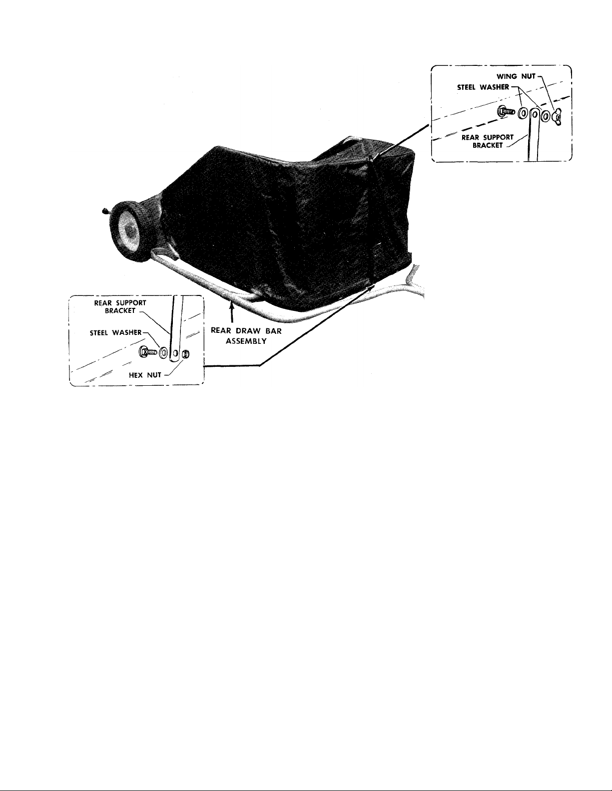
Your Two-Stage Sweeper has been assembled at
the factory except for the Front Draw Bar
Assembly and the Hopper which has been
shipped in the storage position.
To assemble, slide the Front Draw Bar onto the
Rear Draw Bar as shown and fasten securely with
nuts and bolts provided. To prepare the Hopper
for operation, remove the Rear Support Bracket
from the underside of the Hopper, and assemble
to the Lower Mounting Bolt of the Hopper as
shown above. Lift the Upper Frame and assemble
the other end of the support to the Top Mounting
Bolt as shown;
For Storage—The Hopper can be collapsed by
removing the support from the Top Mounting
Bolt only, allowing the Hopper and support to fold
down to the storage position.
OPERATION
Your Sweeper is a precision piece of equipment.
Engineering skill and experience have been
combined to provide the ultimate in safety and
efficiency. However, as with any type of precision
equipment, carelessness or error on the part of
the operator can result in damage to your
equipment. Therefore, exercise caution at all
times and do not subject your sweeper to misuse.
SWEEPING SPEED
Your sweeper has been designed to operate at
approximately AVz mph which is a fast walk and in
the middle of the range of most riding mower
speeds. Varying conditions may dictate another
speed and therefore, it is recommended you try
sweeping at different speeds to find the one most
suited to your conditions.
BRUSH HEIGHT ADJUSTMENT
To adjust your unit to the best operating height
adjustment, press the adjust lever in an outward
direction until the trunnion on the adjust lever
clears the end plate.
Move the lever UP for greater clearance between
lawn and brush or down for less clearance. After
the desired clearance is obtained allow the adjust
lever to spring back locking the trunnion in the
proper positioning hole.
Follow the same procedure for the opposite
wheel. See figure 1.
Page 3

Figure 1
DUMPING OF SWEEPER
Your sweeper can be dumped very easily without
removing or disconnecting a part. Simply lift the
hopper as shown and swing it over the sweeper
and dump. See figure 2.
LUBRICATION
The bearings in your Sweeper have been
prelubricated at the factory, however, it is
recommended that a few drops of light oil should
be added to the impeller and brush shaft bearings
twice a year. Also, the wheels and pinions should
be removed, the axles cleaned and an even coat of
light oil applied. See figure 3.
A
If you are planning on dumping your
Sweeper near a fire use care not to
get too close, the brushes can be
destroyed by excessive heat or
flame.
CAUTION
Figure 3
Figure 2
Page 4

19468-6
19468-7
TMO-285A
197-468A
and
63584
39 41
All Unnumbered Parts Interchangeable With
Opposite Side.
Page 5

PARTS LIST FOR MODELS 19468-6,19468-7, TMO-285A, 197-468A AND 63584
REF.
PART
NO.
NO.
1 4111-92
2 1652-13
3 1629-56
4 1530-6
4111-91
5
6 2120-69
7 2626-74
1548-12
8
9 2651-49
10 1632-229
11 1650-21
12 1540-17
DESCRIPTION
Assembly—End Plate R.H.
Bearing
Retai ner— Bear! ng
Rivet (3/16 Dia. X5/16)
Assembly—End Plate L.H.
Assembly—Pulley
Pulley
Rollpin (.156 Dia. x1 V4)
Belt (3/8 Round Sect.)
Shaft—Brush Drive (Short)
Ring—Retainer
Washer—Flat (5/8x15/16
xl/16)
13 2632-231
14 4703-24
1507-12 Screw (10-32 X1 -1 /8 Sems)
*15
16
3703-25
*17
1507-8
3118-44 Assembly—Dust Cover R.H.
18
Ю 2155-18
Shaft—Brush Drive (Long)
Baffle—Top
Baffle—Front
Screw (10-32 X 3/8 Sems)
Assembly—Wheel Adj.
Lever
20
21
22
2643-18
3118-45
1631-39
Knob—Wheel Adjust
Assembly—Dust Cover L.H.
Axle—Wheel
23 1552-13 Washer—Bowed
24
1657-45
*25
1038
26 4622-98
27 2679-2
Bushing—Spacer
Nut—Hex
Cover—Sweeper
Ass’y- Brush and Channel
28 2182-7 Assembly—Brush Retainer
*29 1509-31 Bolt(1 /4-20 X1-1 /8 Hex Hd.)
*30
1538-8
Nut (t^-20 Hex Lock)
31 1025 Washer—Lock (5/16 Split)
32 1671-1 Pawl
33 2692-6
34 2692-7
35
3108-148
36
4636-18
37
1652-52
38
3619-58 Tire
Pinion R.H.
Pinion L.H. Hd.)
Assembly—Wheel
Wheel—Gear & Rim
Bushing
*39 141 Washer (3/8x7/8x3/16)
142 Cotter Pin (1 /8x5/8)
*40
41
2674-32 Cap—Hub
42
4697-13
*43 1509-44
Draw—Bar—Rear
Bolt(5/16-18 x3/4 Sem Hex)
REF.
*44
*48 769
NO.
PART
NO.
DESCRIPTION
1538-6 Nut (5/16-18 Hex Lock)
45 4697-14
1552-14
46
47
1132-128
Draw—Bar—Front (R.H.)
Washer—Bowed
Ass’y.—Bracket & Pin
Bolt (5/16-18x2-5/8
Hex Hd.)
49
4647-29 Frame Catcher—Lower
50
4647-30
51 0773-13
52
1513-87 Bolt—Shouider (Pivot)
*53
1538-13 Nut(3/8-16 Hex Lock)
54
2603-77 Brace—Frame
Frame Catcher—Upper
Basket—Fabric
55 4709-24 Panel—Catcher Bottom
*56
1095
57
1694-26
*58
1507-6 Bolt (10-32 X 3/8 Truss Hd.)
*59
1534-8 Nut (10-32 Hex Lock)
*60 1507-11
63 1513-93
64
1694-34
65 2723-4
66
1629-63 Retainer—Skirt
67
1693-3 Skirt
1117
*68
Screw (10-32x1/2 Philips)
Clamp
Screw (10-32 X 3/8 Sems)
Bolt (5/16x1-3/8 Special)
Coupling—Half (Clamp)
Scraper—Impeller Pulley
Screw (10-32 X 3/8 Phillips
Hd.)
•69 1540-125
Washer (.59 x 1 -1 /8 x .015)
*70 70 Nut (5/16-18 Hex)
71
1540-32
72 1522-1
Washer (.78 X1-1/4 X.015)
Screw (10-12x5/8 Sheet
Metal)
73
1509-90
74
1018
75
1632-228 Shaft—Impeller (Short)
76 2632-230
77
1530-1 Rivet—(3/16.Dia. x 1 /4 Truss
78
1540-81
79
4697-15 Draw & Bar—Front (L.H.)
80
1509-38
81
1543-69 Washer (21 /64 x 3/4 x 3/32
Bolt (V4-20 X11/4 Hex Hd.)
Lockwasher(1^ Std. Split)
Shaft—Impeller (Long)
Washer(17/64x 3/4 xl/16)
Bolt (10-32x3/8 Hex Hd.)
Nylon)
82
2653-28 Support
83
1509-69 Bolt (1/4-20x1 3/4 Hex Hd.)
84
1539-79
Nut (V4-2O Wing-Lock)
‘Standard Harbware Item—May Be Purchased Locally
Page 6

 Loading...