


For Parts Call 606-678-9623 or 606-561-4983
For Parts Call 606-678-9623 or 606-561-4983
USER MANUAL
Gas String Trimmers/Brushcutters
Models : MT3075/ MT3090/MT30775/ MT30790
MT3075
MT3090
MT30775
MT30790
WARNING • PLEASE READ
For your own safety please read this manual before attempting to operate your new unit. Failure to follow instructions can result in serious personal injury. Spend a few moments to familiarize yourself with
your trimmer before each use.
PN 9096-334601 Printed in Taiwan
www.mymowerparts.com
www.mymowerparts.com

For Parts Call 606-678-9623 or 606-561-4983
For Parts Call 606-678-9623 or 606-561-4983
INTRODUCTION 1 - GENERAL INFORMATION
PLEASE READ
Dear Customer,
Thank you for purchasing a McCulloch product. With proper operation and maintenance, it will provide you with years
of service.
In order to make the best use of your investment, be CER-
TAIN to familiarize yourself with the contents of the
ENTIRE user manual before attempting to operate and
maintain your unit.
Be sure to carefully follow the step-by-step instructions in
this manual to start, operate and maintain your new product.
In the manual there will be the following call-outs: NOTE:,
WARNING / CAUTION and WARRANTY.
A NOTE: is used to convey additional information, to high-
light a particular explanation, or to expand a step description.
A WARNING or CAUTION identifies a procedure which, if
not undertaken or if improperly done, can result in serious
personal injury and/or damage to the unit.
The (WARRANTY SYMBOL) serves notice that unless
instructions or procedures are followed, any damage
caused will void the warranty and repairs will be at owner’s
expense.
Pay particular attention to the safety precautions. They are
written for your protection and contain important information you must know to safely operate your chain saw.
FOR WARRANTY OR SERVICE CONTACT THE NEAR-
EST AUTHORIZED SERVICE CENTER - LOCATE YOUR
NEAREST SERVICE CENTER BY CALLING THE TOLL
FREE NUMBER IN THIS MANUAL.
TABLE OF CONTENTS
1 GENERAL INFORMATION . . . . . . . . . . . . . . . . . . . . . . . . . .2
1-1. Specifications
2 GENERAL IDENTIFICATION . . . . . . . . . . . . . . . . . . . . . . . . .3
2-1. General Identification
2-2. Safety Features
3 SAFETY PRECAUTIONS . . . . . . . . . . . . . . . . . . . . . . . . . . . .4
3-1. What To Do
3-2. Brush/Grass Blade Safety Precautions
3-3. What No To Do
3-4. International Symbols
4 ASSEMBLY INSTRUCTIONS . . . . . . . . . . . . . . . . . . . . . . . . .6
4-1. “P” Handle Assembly
4-2. “J” Handle Assembly
4-3. Blade Gurd Installation
4-4. Debris Shield
4-5. Stringhead Installation
4-6. Debris Shield Installation
4-7. Blade Installation
4-8. Installing the Attachment
5 FUEL AND LUBRICATION . . . . . . . . . . . . . . . . . . . . . . . . .10
5-1. Fuel
5-2. Mixing Fuel
5-3. Fuel Mixing Table
5-4. Recommended Fuels
5-5. Fuel and Lubrication Symbols
6 OPERATING INSTRUCTIONS . . . . . . . . . . . . . . . . . . . . . . .11
6-1. Shoulder Harness
6-2. Starting a Cold Engine
6-3. To Stop Engine
6-4. Warm Engine Start
6-5. Idling/Carburetor Adjustment
7TRIMMING INSTRUCTIONS . . . . . . . . . . . . . . . . . . . . . . . .13
7-1. Additional Safety Precautions
7-2. Stringhead Line Release
7-3. Trimming Procedures
7-4. Cutting With Blades
7-5. Using Weed Blades
7-6. Using a Brush Blade
8 MAINTENANCE INSTRUCTIONS . . . . . . . . . . . . . . . . . . . .15
8-1. Replacing Cutter Line
8-2. Air Filter
8-3. Fuel Cap / Fuel Filter
8-4. Carburetor Adjustment
8-5. Spark Plug
8-6. Spark Arrester Screen
8-7. Debris Shield Knife Sharpening
8-8. Storing a Unit
9TROUBLESHOOTING THE ENGINE . . . . . . . . . . . . . . . . . .19
10 PART LIST . . . . . . . . . . . . . . . . . . . . . . . . . . . . . . . . . . . . . .20
1
www.mymowerparts.com
www.mymowerparts.com

For Parts Call 606-678-9623 or 606-561-4983
For Parts Call 606-678-9623 or 606-561-4983
1-1. SPECIFICATIONS
Engine Type . . . . . . . . . . . . . . . . . . . . . . . . . . . . . . . . . . . . . . . . . . . . . . .Air-cooled, 2-Cycle, Chrome Cylinder
Displacement . . . . . . . . . . . . . . . . . . . . . . . . . . . . . . . . . . . . . . . . . . . . . .30cc / 1.8 ci
Dry Weight (MT3075/MT3090) . . . . . . . . . . . . . . . . . . . . . . . . . . . . . . . .14.1 lbs. / 6.4 kg
(MT30775/MT30790) . . . . . . . . . . . . . . . . . . . . . . . . . . . . . .14.3 lbs. / 6.5 kg
Fuel Capacity . . . . . . . . . . . . . . . . . . . . . . . . . . . . . . . . . . . . . . . . . . . . . .18.6 oz. / 550 ml
Drive Shaft Length (MT3075/MT3090) . . . . . . . . . . . . . . . . . . . . . . . . . .52” / 132cm
(MT30775/MT30790) . . . . . . . . . . . . . . . . . . . . . . .26” + 26” / 66cm + 66cm
Cutting Swath (Twin Line Head ) . . . . . . . . . . . . . . . . . . . . . . . . . . . . . . .17" / 43cm
(Blade - MT3090/MT30790) . . . . . . . . . . . . . . . . . . . . . .9” / 23cm
Handle (MT3075) . . . . . . . . . . . . . . . . . . . . . . . . . . . . . . . . . . . . . . . . . . .“P” Handle
(MT30775/MT3090/MT30790) . . . . . . . . . . . . . . . . . . . . . . . . . . . “J” Handle
Carburetor . . . . . . . . . . . . . . . . . . . . . . . . . . . . . . . . . . . . . . . . . . . . . . . .Primer / Diaphragm Type
Ignition . . . . . . . . . . . . . . . . . . . . . . . . . . . . . . . . . . . . . . . . . . . . . . . . . . .Electronic
Spark Plug . . . . . . . . . . . . . . . . . . . . . . . . . . . . . . . . . . . . . . . . . . . . . . . .Champion DJ8J or equivalent
Drive . . . . . . . . . . . . . . . . . . . . . . . . . . . . . . . . . . . . . . . . . . . . . . . . . . . .Clutch
www.mymowerparts.com
www.mymowerparts.com
2

For Parts Call 606-678-9623 or 606-561-4983
For Parts Call 606-678-9623 or 606-561-4983
2 - GENERAL IDENTIFICATION
20
MT3075
7A
MT3075/MT30775
1
2
21
MT30790
10
7B
9
18
8
19
11
6
3
13
15
14
MT3090/MT30790
3
5
16
17
4
2-1.GENERAL IDENTIFICATION
1. STRINGHEAD
2. CUTTER LINE
3. DEBRIS SHIELD
4. BLADE
5. BLADE GUARD
6. DRIVE SHAFT ASSEMBLY
7A. PHANDLE (MT3075)
7B. J HANDLE (MT3090/MT30775/ MT30790)
8. THROTTLE TRIGGER
9. IGNITION ON/OFF SWITCH
10. SAFETY TRIGGER
11. CHOKE LEVER
12. FUEL TANK
13. AIR FILTER COVER
14. STARTER HANDLE
15. MUFFLER SHIELD
16. PRIMER BULB
17. SPARK ARRESTOR SCREEN
18. HARNESS (MT3090/MT30775/ MT30790)
19. COUPLER (MT30775/ MT30790)
20. SOCKET WRENCH (MT3090/ MT30790)
21. HOLDING PIN
1
2
12
2-2. SAFETY FEATURES
Numbers preceding the descriptions correspond with numbers on preceding page to help you locate the safety feature.
5 BLADE GUARD must be installed to prevent debris
from spraying up into the operator and to protect the
operator form rotating blade.
15 MUFFLER SHIELD helps prevent hands, body and/or
combustible materials from making contact with a hot
muffler.
17 SPARK ARRESTER SCREEN retains carbon and
other flammable particles over 0.023" (.6 mm) in size
from exhaust flow.
NOTE: Compliance with local, state and federal laws
and/or regulations governing the use of a spark arrester
screen is the user’s responsibility. See Safety
Precautions (Section 3) and Maintenance Instructions
(Section 8) for additional information.
3
www.mymowerparts.com
www.mymowerparts.com

For Parts Call 606-678-9623 or 606-561-4983
For Parts Call 606-678-9623 or 606-561-4983
3 - SAFETY PRECAUTIONS
3-1. WHAT TO DO
READ YOUR USER MANUAL AND ALL SUPPLEMENTS
(IF ANY ENCLOSED) THOROUGHLY BEFORE OPERATING YOUR UNIT.
1. CLOTHING - Always wear heavy, long pants, boots,
gloves and long sleeve shirt. Do not wear loose clothing, jewelry, short pants, sandals, or go barefoot.
Secure hair so it is at shoulder level. Always wear a
hard hat, a safety face shield, or safety glasses for eye
protection and a good grade of ear plugs or other
sound barriers for hearing protection.
2 FUELING - Mix and pour fuel outdoors where there
are no sparks and flames. Slowly remove the fuel cap
only after stopping the engine. Do not smoke while
fueling or mixing fuel. Wipe spilled fuel from the unit.
Move at least 30 ft (9m) away from the fueling source
(gas can) and site before starting unit.
3. COMPLY WITH ALL FIRE PREVENTION REGULATIONS. COMPLIANCE WITH ALL LOCAL, STATE,
OR FEDERAL LAWS IN THE UNITED STATES IS
THE USER’S RESPONSIBILITY.Your unit comes with
a spark arrester screen. Replacement spark arrester
screen kits are available at your nearest McCulloch
Authorized Service Center listed under “SAWS” in
your Telephone Directory Yellow Pages.
4. TURN UNIT OFF before setting it down.
5. ALWAYS HOLD UNIT FIRMLY WITH BOTH HANDS,
the thumb and fingers encircling the handles.
6. KEEP ALL SCREWS AND FASTENERS TIGHT.
Never operate this equipment if it is improperly adjusted or not completely and securely assembled.
7. KEEP HANDLES DRY, clean and free of fuel mixture.
8. KEEP STRINGHEAD AS CLOSE TO GROUND AS
PRACTICAL. Avoid hitting small objects with stringhead. When cutting on a slope, stand below stringhead.
9. CHECK AREA YOU WILL BE TRIMMING FOR
DEBRIS that may be struck or thrown during operation.
10. KEEP ALL PARTS OF YOUR BODY AND CLOTHING
AWAY FROM STRINGHEAD when starting or running
engine. Before starting engine, make sure stringhead
will not come in contact with any obstacle.
11. STOP ENGINE before examining cutting line.
12. STORE EQUIPMENT AWAY FROM POSSIBLE IGNITION SOURCES, such as gas-powered water
heaters, clothes dryers, or oil-fired furnaces, portable
heaters, etc.
13. ALWAYS KEEP the debris shield, stringhead, and
engine free of debris build-up.
14. OPERATION OF EQUIPMENT should always be
restricted to mature and properly instructed individuals.
3-2 BRUSH / GRASS BLADE SAFETY PRE-
CAUTIONS
1. FOLLOW ALL WARNINGS and instructions regarding
operation and blade installation.
2. BLADE CAN VIOLENTLY THRUST AWAY FROM
MATERIAL IT CANNOT CUT - Blade thrust can
cause amputation of arms or legs. Keep people and
animals 50 feet (15 meters) away in all directions. If
blade contacts foreign objects during operation, turn off
engine and allow coasting blade to stop. Then check
blade for damage. Always discard blade if it is warped
or cracked.
3. BLADE THROWS OBJECTS VIOLENTLY - You can be
blinded or injured. Wear eye, face, and leg protection.
Always clear work area of any foreign objects before
using blade. Keep people and animals 50 feet (15
meters) away in all directions.
4. INSPECT YOUR TRIMMER AND ATTACHMENTS
BEFORE EACH USE - Never use unless all bladeattaching hardware is properly installed.
5. BLADE COASTS AFTER THROTTLE IS RELEASED A coasting blade can cut you or bystanders. Before performing any service on the blade, always turn off
engine, and be sure coasting blade has stopped.
6. 100-FOOT (30 meters) DIAMETER HAZARD ZONE Bystanders can be blinded or injured. Keep people and
animals 50 feet (15 meters) away in all directions.
3-3. WHAT NOT TO DO
1. DO NOT USE ANY OTHER FUEL than that rec-
ommended in your manual. Always follow instructions in the Fuel and Lubrication section of this manual. Never use gasoline unless it is properly mixed with
2-cycle engine lubricant. Permanent damage to engine
will result, voiding manufacturer’s warranty.
2. DO NOT SMOKE while refueling or operating equipment.
3. DO NOT OPERATE UNIT WITHOUT A MUFFLER and
properly installed muffler shield.
4. DO NOT TOUCH or let your hands or body come in
contact with a hot muffler or spark plug wire.
5. DO NOT OPERATE UNIT IN AWKWARD POSITIONS,
off balance, outstretched arms, or one-handed. Always
use two hands when operating unit with thumbs and
fingers encircling the handles.
6. DO NOT RAISE STRINGHEAD above ground level
while unit is operating. Injury to operator could result.
7. DO NOT USE UNIT FOR ANY PURPOSES OTHER
than trimming lawn or garden areas.
8. DO NOT OPERATE UNIT FOR PROLONGED PERIODS. Rest periodically.
9. DO NOT OPERATE UNIT WHEN TIRED, ILL OR
UNDER THE INFLUENCE OF ALCOHOL OR DRUGS
OR MEDICATION.
www.mymowerparts.com
www.mymowerparts.com
4
For Parts Call 606-678-9623 or 606-561-4983
For Parts Call 606-678-9623 or 606-561-4983
2 - SAFETY PRECAUTIONS
12. DO NOT operate your unit near or around flammable
liquids or gases whether in or out of doors. An explosion and/or fire may result. Never start or run the unit
inside a closed room or building, breathing exhaust
fumes can kill.
13. DO NOT USE ANY OTHER CUTTING ATTACH-
MENT. Use only McCulloch replacement parts
and accessories, which are designed specifically to
enhance the performance and maximize the safe
operation of our products. Failure to do so may cause
poor performance and possible injury. Use only the
stringhead supplied with this product.
other cutting attachment
will void your factory warranty and could result in
serious bodily injury. (Model MT3075, MT3090)
. Use of such attachments
Do not use any
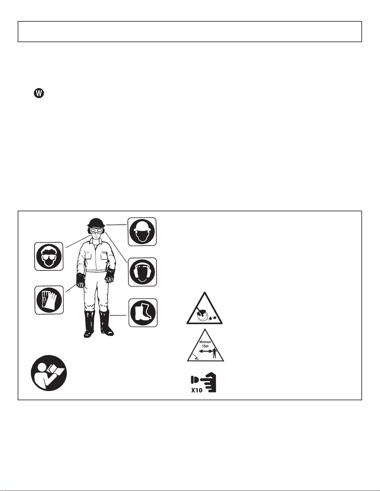
3-4.INTERNATIONAL SYMBOLS
Read the User Manual.
Use of these personal safety items is highly recommended to reduce the risk of accidental injury.
Minimum operating distance
Pump the primer bulb 10 times.
5
www.mymowerparts.com
www.mymowerparts.com
For Parts Call 606-678-9623 or 606-561-4983
For Parts Call 606-678-9623 or 606-561-4983
4 - ASSEMBLY INSTRUCTIONS
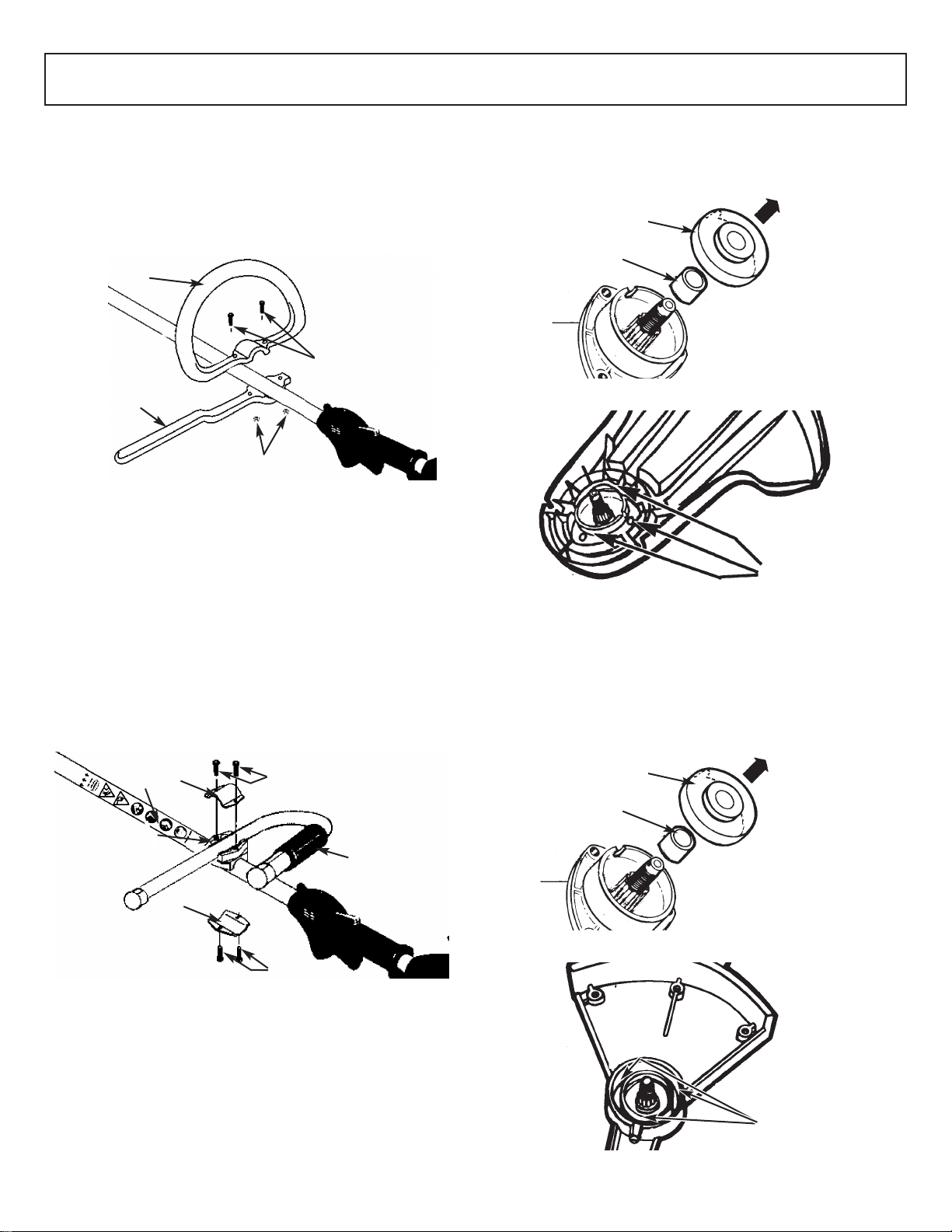
4-1. “P” HANDLE ASSEMBLY (MT3075)
1. To install handle onto unit, you will need the following
components from your user kit: “P” handle (A & B),
screws (C) and nuts (D). (Figure 4-1A).
2. Install the handle (B) on the shaft 160-200mm from
throttle and tighten the 2 screws (C) and nuts (D).
A
C
B
D
4-1A
4-2. “J” HANDLE ASSEMBLY (MT3090/
MT30775/MT30790)
1. To install handle onto unit, you will need the following
components from your user kit: “J” handle (A), middle
clamp housing (B), upper and lower clamps (C) and
screws (D). (Fig. 4-2A)
2. Install the middle clamp housing (B) on the shaft near
the arrows on the sticker (warning label E ), put the lowerclamp (C) under shaft and tighten with 2 screws (D).
3. Install the J handle (A) on the middle clamp housing,
then put the upper clamp (C) over J-handle and tighten
the other 2 screws (D).
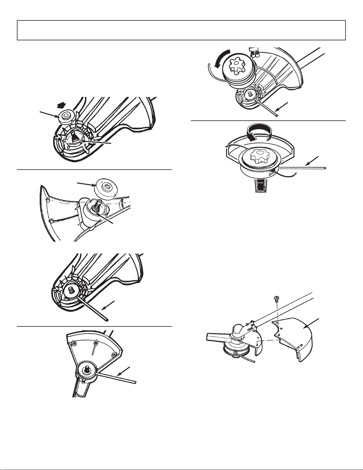
3. Reinstall the gear collar (A). Ensure the collar spacer
(C) is in place or the collar will rub the gear housing
(Figure 4-3A).
A
C
4-3A
B
4-3B
4-4. DEBRIS SHIELD (MT3090/MT30790)
1. Remove gear collar (A) from the threaded gear housing
shaft. Insure collor spacer (C) is in place (Figure 4-4A).
2. Install debris shield with 3 screws (B) provided in the
hardware bag. (Figure 4-4B)
E
C
B
C
D
A
D
4-2A
4-3. BLADE GUARD INSTALLATION
(MT3075/MT30775)
1. Remove gear collar (A) from the threaded gear housing
shaft (Figure 4-3A).
2. Place the shield on the gear housing and align the
mounting holes. Insert screws (B), found in the hardware bag as shown in illustration and tighten securely
(Figure 4-3B).
www.mymowerparts.com
www.mymowerparts.com
A
C
4-4A
B
4-4B
6
For Parts Call 606-678-9623 or 606-561-4983
For Parts Call 606-678-9623 or 606-561-4983
4 - ASSEMBLY INSTRUCTIONS 4 - ASSEMBLY INSTRUCTIONS
4-5. STRINGHEAD INSTALLATION
1. Install gear collar (A) ensuring that collar spacer (B) is
in place (Figure 4-5A).
2. Insert holding pin (C) and thread stringhead onto shaft.
Tighten stringhead by hand only (Figures 4-5B and 45C).
A
B
MT3075/
MT30775
MT3090/
MT30790
A
C
MT3075/
MT30775
MT3090/
MT30790
C
MT3075/
MT30775
MT3090/
MT30790
4-5A
B
C
4-5C
4-6. DEBRIS SHIELD INSTALLATION
(MT3090/MT30790)
1. Turn the unit over and with screws found in the hardware bag install the debris shield (A) as shown (Figure
4-6A).
CAUTION
Debris shield must be installed to properly dispense cutter
line and protect operator.
REMINDER
Be sure to remove holding pin before starting unit.
MT3090/MT30790
A
C
4-5B
www.mymowerparts.com
www.mymowerparts.com
4-6A