

Page 1

Operator’s Manual
4-Cycle Gasoline Trimmer
Model H70SS
SAVE THESE INSTRUCTIONS
For a list of service providers, please refer to the phone numbers
found on page 6 or at the end of the Trouble Shooting section of
this manual.
DO NOT RETURN THE UNIT TO THE RETAILER. PROOF OF
PURCHASE WILL BE REQUIRED FOR WARRANTY SERVICE.
THIS PRODUCT IS COVERED BY ONE OR MORE U.S. PATENTS.
OTHER PATENTS PENDING.
Service on this unit both within and after the warranty period should
be performed only by an authorized and approved service dealer.
All information, illustrations, and specifications in this manual
are based on the latest product information available at the
time of printing. We reserve the right to make changes at any
time without notice.
Copyright© 2007 MTD SOUTHWEST INC, All Rights Reserved.
P/N 769-02747 (1/07)
TABLE OF CONTENTS
Service Information . . . . . . . . . . . . . . . . . . . . . . . . . . . . . . . .1
Rules for Safe Operation . . . . . . . . . . . . . . . . . . . . . . . . . . . .1
Know Your Unit . . . . . . . . . . . . . . . . . . . . . . . . . . . . . . . . . . .3
Assembly Instructions . . . . . . . . . . . . . . . . . . . . . . . . . . . . . .4
Stopping Instructions . . . . . . . . . . . . . . . . . . . . . . . . . . . . . .4
Operating Instructions . . . . . . . . . . . . . . . . . . . . . . . . . . . . . .4
Maintenance Instructions . . . . . . . . . . . . . . . . . . . . . . . . . . .5
Cleaning and Storage . . . . . . . . . . . . . . . . . . . . . . . . . . . . . .6
Troubleshooting Chart . . . . . . . . . . . . . . . . . . . . . . . . . . . . . .7
Specifications . . . . . . . . . . . . . . . . . . . . . . . . . . . . . . . . . . . .7
Warranty Information . . . . . . . . . . . . . . . . . . . . . . . . . . . . . . .8
Parts List . . . . . . . . . . . . . . . . . . . . . . . . . .Inside Back Cover
WARNING: When using the unit, you must follow
the safety rules. Please read these instructions
before operating the unit in order to ensure the
safety of the operator and any bystanders. Please
keep these instructions for later use.
READ ALL INSTRUCTIONS BEFORE OPERATING
• Read the instructions carefully. Be familiar with the controls
and proper use of the unit.
• This unit was not designed to be used as a brushcutter. Do
not attach or operate this unit with any type of brushcutting
blade or brushcutting attachment.
• Do not operate this unit when tired, ill, or under the influence
of alcohol, drugs, or medication.
• Children and teens under the age of 15 must not use the
unit, except for teens guided by an adult.
• All guards and safety attachments must be installed properly
before operating the unit.
• Inspect the unit before use. Replace damaged parts. Check
for fuel leaks. Make sure all fasteners are in place and secure.
Replace parts that are cracked, chipped, or damaged in any
way. Do not operate the unit with loose or damaged parts.
• Carefully inspect the area before starting the unit. Remove all
debris and hard or sharp objects such as glass, wire, etc.
• Be aware of the risk of injury to the head, hands and feet.
• Clear the area of children, bystanders, and pets. At a minimum,
keep all children, bystanders, and pets outside a 50 feet (15 m)
radius; there still may be a risk to bystanders from thrown
objects. Bystanders should be encouraged to wear eye
protection. If you are approached, stop the unit immediately.
• Use only 0.105 inches (2.67 mm) diameter original equipment
manufacturer replacement line. Never use metal-reinforced
line, wire, or rope. These can break off and become dangerous
projectiles.
• Squeeze the throttle control and check that it returns automatically to the idle position. Make all adjustments or repairs
before using unit.
RULES FOR SAFE OPERATION
• IMPORTANT SAFETY INSTRUCTIONS •
Page 2

2
SAFETY WARNINGS FOR GAS UNITS
• Store fuel only in containers specifically designed and
approved for the storage of such materials.
• Avoid creating a source of ignition for spilled fuel. Do not
start the engine until fuel vapors dissipate.
• Always stop the engine and allow it to cool before filling the
fuel tank. Never remove the cap of the fuel tank, or add fuel,
when the engine is hot. Never operate the unit without the
fuel cap securely in place. Loosen the fuel tank cap slowly to
relieve any pressure in the tank.
• Add fuel in a clean, well-ventilated outdoor area where there
are no sparks or flames. Slowly remove the fuel cap only
after stopping engine. Do not smoke while fueling or mixing
fuel. Wipe up any spilled fuel from the unit immediately.
Always wipe unit dry before using.
• Move the unit at least 30 feet (9.1 m) from the fueling source
and site before starting the engine. Do not smoke or allow
sparks and open flames near the area while adding fuel or
operating the unit.
WHILE OPERATING
• Never start or run the unit inside a closed room or building.
Breathing exhaust fumes can be fatal. Operate this unit only
in a well-ventilated outdoor area.
• Wear safety glasses or goggles that meet ANSI Z87.1
standards and are marked as such. Wear ear/hearing
protection when operating this unit. Wear a face or dust
mask if the operation is dusty.
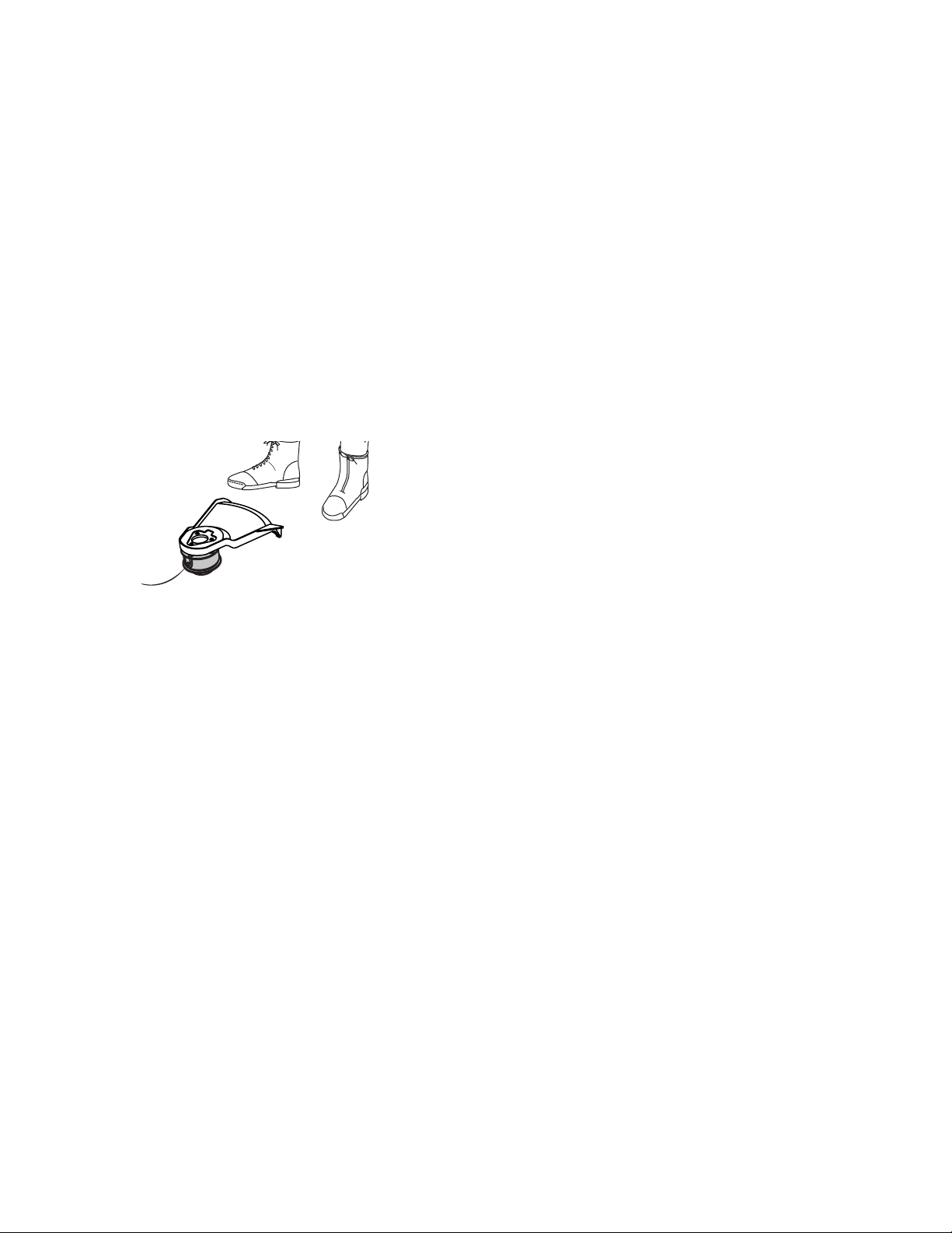
• Wear heavy long pants, boots, gloves and a long sleeve shirt.
Do not wear loose clothing, jewelry, short pants, sandals or
go barefoot. Secure hair above shoulder level.
• The cutting attachment shield must always be in place while
operating the unit as a trimmer. Do not operate unit without
both trimming lines extended, and the proper line installed.
Do not extend the trimming line beyond the length of the
shield.
• This unit has a clutch. The cutting attachment remains
stationary when the engine is idling. If it does not, have the
unit adjusted by an authorized service technician.
• Adjust the D-handle to your size in order to provide the best
grip.
• Be sure the cutting attachment is not in contact with anything
before starting the unit.
• Use the unit only in daylight or good artificial light.
• Avoid accidental starting. Be in the starting position
whenever pulling the starter rope. The operator and unit must
be in a stable position while starting. Refer to
Starting/Stopping Instructions.
RULES FOR SAFE OPERATION
• Use the right tool. Only use this tool for its intended purpose.
• Do not overreach. Always keep proper footing and balance.
• Always hold the unit with both hands when operating. Keep a
firm grip on both handles or grips.
• Keep hands, face, and feet at a distance from all moving
parts. Do not touch or try to stop the cutting attachment
when it rotates.
• Do not touch the engine, gear housing or muffler. These parts
get extremely hot from operation, even after the unit is turned off.
• Do not operate the engine faster than the speed needed to
cut, trim or edge. Do not run the engine at high speed when
not cutting.
• Always stop the engine when cutting is delayed or when
walking from one cutting location to another.
• If you strike or become entangled with a foreign object, stop
the engine immediately and check for damage. Do not
operate before repairing damage. Do not operate the unit
with loose or damaged parts.
• Stop the unit, switch the engine to off, and disconnect the
spark plug for maintenance or repair.
• Use only original equipment manufacturer replacement parts
and accessories for this unit. These are available from your
authorized service dealer. Use of any unauthorized parts or
accessories could lead to serious injury to the user, or
damage to the unit, and void your warranty.
• Keep unit clean of vegetation and other materials. They may
become lodged between the cutting attachment and shield.
• To reduce fire hazard, keep the engine and muffler free from
grass, leaves, and excessive grease.
AFTER USE
• Clean cutting blades with a household cleaner to remove any
gum buildup. Oil the blade with machine oil to prevent rust.
• Lock up and store the cutting blade in an appropriate area to
protect the blade from unauthorized use or damage.
OTHER SAFETY WARNINGS
• Never store a fueled unit inside a building where fumes may
reach an open flame or spark.
• Allow the engine to cool before storing or transporting. Be
sure to secure the unit while transporting.
• Store the unit in a dry area, locked up or up high to prevent
unauthorized use or damage, out of the reach of children.
• Never douse or squirt the unit with water or any other liquid.
Keep handles dry, clean and free from debris. Clean after
each use, see Cleaning and Storage instructions.
• Keep these instructions. Refer to them often and use them to
instruct other users. If you loan someone this unit, also loan
them these instructions.
SAVE THESE INSTRUCTIONS
WARNING: Gasoline is highly flammable, and its
vapors can explode if ignited. Take the following
precautions:
Page 3

This operator's manual describes safety and international
symbols and pictographs that may appear on this product.
Read the operator's manual for complete safety, assembly,
operating and maintenance and repair information.
SYMBOL MEANING
• SAFETY ALERT SYMBOL
Indicates danger, warning or caution. May be
used in conjunction with other symbols or
pictographs.
• WARNING - READ OPERATOR'S MANUAL
Read the operator’s manual(s) and follow all
warnings and safety instructions. Failure to do so
can result in serious injury to the operator and/or
bystanders.
• WEAR EYE AND HEARING PROTECTION
WARNING: Thrown objects and loud noise can
cause severe eye injury and hearing loss. Wear
eye protection meeting ANSI Z87.1 standards
and ear protection when operating this unit. Use
a full face shield when needed.
• ON/OFF STOP CONTROL
ON / START / RUN
• ON/OFF STOP CONTROL
OFF or STOP
• KEEP BYSTANDERS AWAY
WARNING: Keep all bystanders, especially
children and pets, at least 50 feet (15 m) from the
operating area.
• THROWN OBJECTS AND ROTATING CUTTER
CAN CAUSE SEVERE INJURY
WARNING: Do not operate without the cutting
attachment shield in place. Keep away from the
rotating cutting attachment.
• SHARP BLADE
WARNING: Sharp blade on cutting attachment
shield. To prevent serious injury, do not touch the
line cutting blade.
APPLICATIONS
• Cutting grass and light weeds
• Edging
• Decorative trimming around trees, fences, etc.
NOTE: The below illustration may differ slightly from your unit.
For example, the picture shows a straight shaft. Your
unit may have a curved shaft.
Cutting Attachment
Shield
Throttle
Control
D-Handle
Cutting
Attachment
Shaft Grip
Shaft
Housing
Line
Cutting
Blade
On/Off Stop Control
KNOW YOUR UNIT
3
Page 4
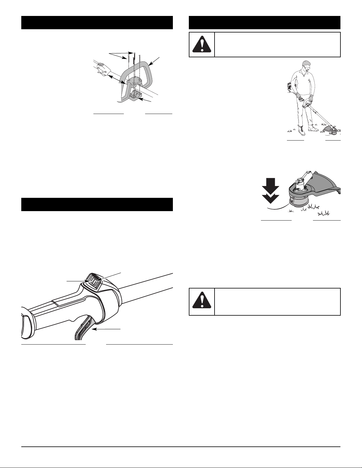
HOLDING THE TRIMMER
Before operating the unit, stand in the
operating position (Fig. 3). Check for the
following:
• The operator is wearing eye protection
and proper clothing
• With a slightly-bent right arm, the
operator’s right hand is holding the
shaft grip
• The operator’s left arm is straight, the
left hand holding the handle
• The unit is at waist level
• The cutting attachment is parallel to the ground and easily
contacts the grass without the need to bend over.
Adjusting Trimming Line Length
The Bump Head cutting
attachment allows you to
release trimming line without
stopping the engine. To
release more line, lightly tap
the cutting attachment on the
ground (Fig. 4) while
operating the trimmer at high
speed.
NOTE: Always keep the trimming line fully extended. Line
release becomes more difficult as cutting line becomes
shorter.
Each time the head is bumped, about 1 inch (25.4 mm) of
trimming line releases. A blade in the cutting attachment shield
will cut the line to the proper length if any excess line is released.
For best results, tap the bump knob on bare ground or hard
soil. If you attempt a line release in tall grass, the engine may
stall. Always keep the trimming line fully extended. Line release
becomes more difficult when the cutting line gets shorter.
NOTE: Do not rest the Bump Head on the ground while the
unit is running.
Some line breakage will occur from:
• Entanglement with foreign matter
• Normal line fatigue
• Attempting to cut thick, stalky weeds
• Forcing the line into objects such as walls or fence posts
TIPS FOR BEST TRIMMING RESULTS
• For best trimming results, operate unit at full throttle.
• Keep the cutting attachment parallel to the ground.
• Do not force the cutting attachment. Allow the tip of the line to
do the cutting, especially along walls. Cutting with more than the
tip will reduce cutting efficiency and may overload the engine.
• Cut grass over 8 inches (200 mm) by working from top to
bottom in small increments to avoid premature line wear or
engine drag.
Fig. 3
WARNING: Always wear eye, hearing, foot and
body protection to reduce the risk of injury when
operating this unit.
OPERATING INSTRUCTIONS
WARNING: Do not remove or alter the line cutting
blade assembly. Excessive line length will make
the clutch overheat. This may lead to serious
personal injury or damage to the unit.
Fig. 4
4
ASSEMBLY INSTRUCTIONS
INSTALLING AND ADJUSTING THE D-HANDLE
If your unit has the D-Handle pre-installed, please follow the
“To Adjust” instructions only.
To Install
1. Remove the screws and
bottom clamp piece that
were installed on the Dhandle for shipping.
2. Place the D-handle over
the shaft housing and onto
the bottom clamp (Fig. 1).
Place it a minimum of 6 in
(15.24 cm) from the end of
the shaft grip.
3. Start screws with a large Flat-head or T-25 Torx
screwdriver. Do not tighten until you make the handle
adjustment.
To Adjust
4. If the D-handle was pre-installed, loosen the screws on the
handle just enough to move it.
5. While holding the unit in the operating position, manuever
the D-handle to the location that provides you the best grip
(Fig. 3).
6. Tighten the clamp screws evenly, until the D-handle is
secure.
(4) Screws
D-Handle
Bottom
Clamp
Fig. 1
Minimum
6 inches
(15.24 cm)
STOPPING INSTRUCTIONS
Note: This unit has a Momentary Switch. The On/Off Contol
Switch will be in the On position at all times.
1. Release your hand from the throttle control. Allow the
engine to cool down by idling.
2. Press the On/Off Stop Control in the OFF (O) position and
hold until the unit completely stops running. (Fig. 2)
STOPPING INSTRUCTIONS
Start/On ( I )
Stop/Off (O)
Throttle
Control
Fig. 2
Page 5
• Cut from left to right.
• Slowly move the trimmer into and out of the cutting area at
the desired height. Move either in a forward-backward or
side-to-side motion. Cutting shorter lengths produces the
best results.
• Trim only when grass and weeds are dry.
• The life of your cutting line is dependent upon:
- Proper adherence of explained trimming techniques
- What vegetation is cut
- Where vegetation is cut
For example, the line will wear faster when trimming against a
foundation wall as opposed to trimming around a tree. It is
normal for some line breakage to occur from regular use.
DECORATIVE TRIMMING
Decorative trimming is accomplished by removing all
vegetation around trees, posts, fences and more.
Rotate the whole unit so that the cutting attachment is at a 30°
angle to the ground (Fig. 5).
Page 6

9. Wind the line in tight even layers in the direction indicated
on the inner reel. (Fig. 10)
NOTE: Failure to wind the line in the direction indicated will
cause the cutting attachment to operate incorrectly.
10. Insert the ends of the line into the two holding slots (Fig. 11).
11. Insert the ends of the line through the eyelets in the outer
spool and place inner reel with spring inside the outer spool
(Fig. 12). Push the inner reel and outer spool together.
While holding the inner reel and outer spool, grasp the ends
and pull firmly to release the line from the holding slots in
the reel.
NOTE: The spring must be assembled on the inner reel before
reassembling the cutting attachment.
12. Hold the inner reel in place and install the Bump Knob by
turning counterclockwise. Tighten securely.
MAINTENANCE AND REPAIR INSTRUCTIONS
6
Installing a Pre Wound Reel
1. Hold the outer spool with one hand and unscrew the Bump
Knob clockwise (Fig. 6). Inspect the bolt inside the Bump
Knob to make sure it moves freely. Replace the Bump
Knob if damaged.
2. Remove the old inner reel from the outer spool
(Fig. 6).
3. Remove the spring from the old inner reel
(Fig. 6).
4. Place the spring in the new inner reel.
NOTE: The spring must be assembled on the inner reel before
reassembling the cutting attachment.
5. Insert the ends of the line through the eyelets in the outer
spool (Fig. 12).
6. Place the new inner reel inside the outer spool. Push the
inner reel and outer spool together. While holding the inner
reel and outer spool, grasp the ends and pull firmly to
release the line from the holding slots in the spool.
7. Hold the inner reel in place and install the Bump Knob by
turning counterclockwise. Tighten securely.
Replacement Parts
For replacement parts, refer to the Accessories / Replacement
Parts section.
Storage
• Store the unit locked up to prevent unauthorized use or
damage.
• Store the unit in a dry, well-ventilated area.
• Store the unit out of the reach of children.
Long Term Storage
If the unit will be stored for an extended time, use the following
storage procedure:
1. Thoroughly clean the unit and inspect it for any loose or
damaged parts. Repair or replace damaged parts and
tighten loose screws, nuts or bolts. The unit is ready for
storage.
Transporting
• Secure the unit while transporting.
Accessories / Replacement Parts
Replacement Line Cartridge 753-1160
Inner Reel Spring 610636
Bump Head Knob Assembly 180814
Shoulder Strap 682075
Fig. 10
Loop
Fig. 9
Holding Slots
Fig. 11
Page 7

TROUBLESHOOTING
CAUSE ACTION
Cutting attachment bound with grass Stop the engine and clean cutting attachment
Cutting attachment out of line Refill with new line
Inner reel bound up Replace the inner reel
Cutting head dirty Clean inner reel and outer spool
Line welded Disassemble, remove the welded section and rewind
Line twisted when refilled Disassemble and rewind the line
Not enough line is exposed Push the bump knob and pull out line until 4 inches
(102 mm) of line is outside of the cutting attachment
CUTTING ATTACHMENT WILL NOT ADVANCE LINE
CAUSE ACTION
Oil, cleaner or lubricant in cutting head Clean and thoroughly dry the cutting head
CUTTING LINE ADVANCES UNCONTROLLABLY
Drive Shaft Housing ........................................................................................................................................................... Aluminum Tube
Throttle Control............................................................................................................................. Finger-Tip Trigger w/Momentary Switch
Approximate Unit Weight (No fuel, with cutting attachment, shield and D-handle)............................................................ 13 lbs. (5.9 kg)
Cutting Mechanism.............................................................................................................................................. Dual String Cutting Head
Line Spool.................................................................................................................................................................... Bump Line Releaser
Line Spool Diameter................................................................................................................................................... 4 inches (101.6 mm)
Trimming Line Diameter......................................................................................................................................... 0.105 inches (2.67 mm)
Cutting Path Diameter ............................................................................................................................................... 17 inches (43.18 cm)
SPECIFICATIONS
DRIVE SHAFT AND CUTTING ATTACHMENT*
7
For engine service and warranty please call 1-800-426-7701
to locate the closest service dealer in your area.
For boom service and warranty please call 1-800-800-7310
Page 8

MANUFACTURER’S LIMITED WARRANTY FOR:
No implied warranty, including any implied warranty of
merchantability or fitness for a particular purpose, applies
after the applicable period of express written warranty above
as to the parts as identified. No other express warranty or
guaranty, whether written or oral, except as mentioned
above, given by any person or entity, including a dealer or
retailer, with respect to any product shall bind MTD Pro LLC
During the period of the Warranty, the exclusive remedy is
repair or replacement of the product as set forth above.
(Some states do not allow limitations on how long an implied
warranty lasts, so the above limitation may not apply to you.)
The provisions as set forth in this Warranty provide the sole
and exclusive remedy arising from the sales. MTD Pro LLC
shall not be liable for incidental or consequential loss or
damages including, without limitation, expenses incurred for
substitute or replacement lawn care services, for
transportation or for related expenses, or for rental
expenses to temporarily replace a warranted product. (Some
states do not allow limitations on how long an implied warranty
lasts, so the above limitation may not apply to you.)
In no event shall recovery of any kind be greater than the amount
of the purchase price of the product sold. Alteration of the safety
features of the product shall void this Warranty. You assume the
risk and liability for loss, damage, or injury to you and your
property and/or to others and their property arising out of the
use or misuse or inability to use the product.
This limited warranty shall not extend to anyone other than the
original purchaser, original lessee or the person for whom it was
purchased as a gift.
How State Law Relates to this Warranty: This warranty gives
you specific legal rights, and you may also have other rights
which vary from state to state.
To locate your nearest service dealer dial 1-800-800-7310.
MTD PRO LLC
P.O. Box 361131
Cleveland, OH 44136-0019
The limited warranty set forth below is given by MTD Pro LLC
with respect to new merchandise purchased and used in the
United States, its possessions and territories.
MTD Pro LLC warrants this product against defects in material
and workmanship for a period of two (2) years commencing on
the date of original purchase and will, at its option, repair or
replace, free of charge, any part found to be defective in material
or workmanship. This limited warranty shall only apply if this
product has been operated and maintained in accordance with
the Operator’s Manual furnished with the product, and has not
been subject to misuse, abuse, commercial use, neglect,
accident, improper maintenance, alteration, vandalism, theft, fire,
water or damage because of other peril or natural disaster.
Damage resulting from the installation or use of any accessory or
attachment not approved by MTD Pro LLC for use with the
product(s) covered by this manual will void your warranty as to
any resulting damage. This warranty is limited to ninety (90) days
from the date of original retail purchase for any MTD Pro product
that is used for rental or commercial purposes, or any other
income-producing purpose.
HOW TO OBTAIN SERVICE: Warranty service is available, WITH
PROOF OF PURCHASE THROUGH YOUR LOCAL
AUTHORIZED SERVICE DEALER. To locate the dealer in your
area check for a listing in the Yellow Pages, call 1-800-800-7310
or write to
P.O. Box 361131, Cleveland, OH 44136-0019
.
This limited warranty does not provide coverage in the
following cases:
A. Tune-ups - Spark Plugs, Carburetor Adjustments, Filters
B. Wear items - Bump Knobs, Outer Spools, Cutting Line,
Inner Reels, Starter Pulley, Starter Ropes, Drive Belts
C. MTD Pro LLC does not extend any warranty for products
sold or exported outside of the United States of America,
its possessions and territories, except those sold through
MTD Pro’s authorized channels of export distribution.
MTD Pro LLC reserves the right to change or improve the design of any
MTD Pro Product without assuming any obligation to modify any product
previously manufactured.
Page 9

Manuel de L’utilisateur
Désherbeuse à gaz à 4-temps
Model H70SS
CONSERVEZ CES INSTRUCTIONS
Pour une liste des fournisseurs agréés, veuillez consulter les numéros
de téléphone en page 6 ou à la fin de la section Résolution des
Pannes de ce manuel.
NO REGRESE SU UNIDAD AL VENDEDOR. PARA SOLICITAR
SERVICIO POR LA GARANTIA, DEBERA PRESENTAR PRUEBA DE
SU COMPRA.
ESTE PRODUCTO ESTA CUBIERTO POR UNA O MAS PATENTES
DE EE.UU., OTRAS PATENTES EN TRAMITE.
El servicio de esta unidad, ya sea durante o después del período
cubierto por la garantía, debe ser realizado solamente por un
proveedor de servicios autorizado y aprobado.
Toutes les informations, illustrations et spécifications contenues dans
ce manuel tiennent compte des dernières informations techniques
disponibles au moment de mettre sous presse. Nous nous réservons
le droit d'y apporter des modifications à tout moment, sans préavis.
Copyright© 2007 MTD SOUTHWEST INC., Tous droits réservés.
P/N 769-02747 (1/07)
TABLE DES MATIÈRES
Service technique . . . . . . . . . . . . . . . . . . . . . . . . . . . . . . . .F1
Consignes de sécurité . . . . . . . . . . . . . . . . . . . . . . . . . . . . .F1
Familiarisez-vous avec votre appareil . . . . . . . . . . . . . . . . .F3
Instructions de montage . . . . . . . . . . . . . . . . . . . . . . . . . . .F4
Instructions d'arrêt . . . . . . . . . . . . . . . . . . . . . . . . . . . . . . .F4
Mode d'emploi . . . . . . . . . . . . . . . . . . . . . . . . . . . . . . . . . .F4
Entretien et réparations . . . . . . . . . . . . . . . . . . . . . . . . . . . .F5
Nettoyage et entreposage . . . . . . . . . . . . . . . . . . . . . . . . . .F6
Tableau de dépannage . . . . . . . . . . . . . . . . . . . . . . . . . . . .F7
Caractéristiques . . . . . . . . . . . . . . . . . . . . . . . . . . . . . . . . .F7
Garantie . . . . . . . . . . . . . . . . . . . . . . . . . . . . . . . . . . . . . . . .F8
Liste des pièces . . . . . . . . . . . . . . . . . . . . .Inside Back Cover
AVERTISSEMENT : Lorsque vous utilisez la
machine, vous devez suivre les consignes de
sécurité. Veuillez lire ces instructions avant d’opérer
la machine pour vous assurer de la sécurité de
l’opérateur et de tout spectateur. Veuillez conserver
ces instructions pour un usage ultérieur.
LISEZ TOUTES LES INSTRUCTIONS AVANT UTILISATION
• Lisez soigneusement cette notice. Familiarisez-vous avec les
commandes et la marche à suivre pour une bonne utilisation
de l'appareil.
• Cet appareil n'est pas conçu pour servir de débroussailleuse.
N'utilisez cet appareil avec aucun type de lame ou
d'accessoire de débroussaillage.
• N’utilisez pas cet appareil lorsque vous êtes fatigué, malade, ou
sous l’influence de l’alcool, de drogues, ou de médicaments.
• Tout enfant ou adolescent de moins de 15 ans ne doit pas
utiliser cet appareil, à moins que l'adolescent soit sous la
supervision d’un adulte.
• Toutes les protections et tous les dispositifs de sécurité
doivent être installés correctement avant utilisation de
l’appareil.
• Inspectez l’appareil avant utilisation. Remplacez les pièces
endommagées. Détectez les fuites de carburant éventuelles.
Assurez-vous que tous les accessoires sont bien en place.
Remplacez les pièces susceptibles d’être fissurées,
ébréchées, ou endommagées. N’utilisez pas cet appareil si
des pièces ont du jeu ou sont endommagées.
• Inspectez la zone avec attention avant de démarrer cet
appareil. Retirez tous les débris et objets durs ou tranchants
tels que du verre, les câbles, etc…
• Soyez conscient des risques de blessures à la tête, aux
mains et aux pieds.
• Eloignez les enfants, les personnes à proximité et les
animaux familiers de la zone d’utilisation. Au minimum, faites
reculer les enfants, les personnes à proximité et les animaux
familiers de 50 pieds (15 m) ; il existe néanmoins un risque
de projectiles pour les personnes à proximité. Encouragezles à porter des lunettes de sécurité. Si quelqu’un
CONSIGNES DE SÉCURITÉ
• IMPORTANTE INFORMACION DE SEGURIDAD •
Page 10

F2
s’approche de vous, arrêtez l’appareil immédiatement.
• Utilisez uniquement un fil de 0,105 pouces (2,67mm) de
diamètre provenant du fabricant. N’utilisez jamais de câbles,
cordons ou pièces renforcées en métal, qui peuvent céder et
devenir des projectiles dangereux.
• Appuyez sur la manette des gaz et vérifiez que le régime du
moteur revienne automatiquement au ralenti. Effectuez tous
les réglages et réparations avant d’utiliser l’appareil.
ALERTES DE SECURITE POUR LES APPAREILS A ESSENCE
• Stockez uniquement le carburant dans des conteneurs
prévus spécifiquement à cet effet et approuvés pour le
stockage de telles substances.
• Evitez tout ce qui pourrait enflammer le carburant renversé.
Ne démarrez pas le moteur avant que les vapeurs de
carburant ne se soient dissipées.
• Coupez toujours le moteur et laissez-le refroidir avant de
remplir le réservoir d’essence. Ne retirez jamais le bouchon
du réservoir d’essence et ne remplissez jamais ce dernier
lorsque le moteur est chaud. Ne démarrez jamais l’appareil
sans avoir bien revissé le bouchon du réservoir d’essence.
Dévissez lentement le bouchon du réservoir d’essence afin
de réduire la pression.
•A
joutez le carburant en extérieur, dans une zone propre, bien
aérée, et dépourvue de toute source d’étincelles ou de flammes.
Dévissez lentement le bouchon du réservoir d’essence
uniquement après avoir arrêté le moteur. Ne fumez pas en
remplissant le réservoir ou en mélangeant le carburant. L’essence
s’étant échappée de l’appareil doit être essuyée immédiatement.
Essuyez l’appareil systématiquement avant utilisation.
• Eloignez l’appareil d’au moins 30 pieds (9,1 m) du site et de
la source du carburant avant de démarrer le moteur. Ne
fumez pas ou assurez-vous qu’il n’y a pas de source
d’étincelles et de flammes, à proximité, lorsque vous ajoutez
du carburant ou faites tourner l’appareil.
LORS DU FONCTIONNEMENT DE L'APPAREIL
• L'appareil ne doit pas être démarré ou opéré à l'intérieur d'un
espace ou d’un bâtiment clos. L’inhalation des fumées
d’échappement peut être fatale. Cet appareil doit fonctionner
uniquement en extérieur, dans une zone bien aérée.
• Portez des lunettes de sécurité conformes aux normes ANSI
Z87.1, lesquelles doivent être indiquées sur les lunettes
mêmes. Portez des bouchons d’oreille et des casques
antibruit lors de l’utilisation de cet appareil. Portez un
masque si l'appareil émet de la poussière.
• Portez un pantalon long et épais, des bottes, des gants et
une chemise à manches longues. Ne portez pas de
vêtements amples, de bijoux, de pantalons courts, de
sandales et ne soyez pas pieds nus. Veillez à ce que vos
cheveux restent au-dessus du niveau des épaules.
• L’écran de l’accessoire de coupe doit toujours être utilisé
lorsque vous vous servez de cet appareil comme
débroussailleuse. N'utilisez jamais cet appareil sans une
longueur suffisante des deux fils de coupe, ces derniers devant
être ceux recommandés par le fabricant. La longueur des fils
de coupe ne doit jamais aller au-delà de celle de l’écran.
• Cet appareil dispose d’un embrayage. L'accessoire de coupe
reste immobile lorsque le moteur tourne au ralenti. Dans le cas
contraire, faites ajuster cet appareil par un technicien agréé.
RULES FOR SAFE OPERATION
•A
justez la poignée D à votre taille afin d’assurer une prise optimale.
• Assurez-vous que l’accessoire de coupe n’est pas en
contact avec tout autre élément avant de démarrer l’appareil.
• Utilisez cet appareil uniquement en plein jour ou si vous
disposez d’un éclairage artificiel suffisant.
• Evitez les démarrages accidentels. Soyez en position de
démarrage lorsque vous tirez sur le cordon du démarreur.
L’utilisateur et l’appareil doivent être sur un sol ferme lors du
démarrage. Référez-vous aux consignes relatives au
démarrage/à l’arrêt de l’appareil.
• Utilisez le bon outil. N’utilisez pas un outil pour des fonctions
pour lesquelles il n’a pas été prévu.
• N’étendez pas trop le bras. Restez toujours à distance et en
équilibre.
• Tenez toujours l’appareil à deux mains lorsqu'il est en marche.
Assurez une prise ferme sur les deux poignées ou grips.
• Gardez vos mains, votre visage et vos pieds à distance des
parties en mouvement. Ne touchez pas et ne tentez pas
d'arrêter l'accessoire de coupe lorsqu'il est en rotation.
• Ne touchez pas au moteur, à la transmission ou au pot
d'échappement. Ces parties deviennent extrêmement chaudes
lors du fonctionnement, même après l'arrêt de l'appareil.
• L'appareil ne doit pas fonctionner à un régime supérieur à
celui adapté pour la coupe ou la tonte. Ne faites pas tourner
le moteur à haut régime lorsque vous ne coupez rien.
• Arrêtez toujours le moteur lorsque la coupe est interrompue
ou lorsque vous vous rendez à une autre aire de coupe.
• Si vous butez ou bloquez sur un objet, arrêtez le moteur
immédiatement et vérifiez que l'appareil n'a pas été
endommagé. Ne redémarrez pas l'appareil avant de l'avoir
réparé. Ne faites pas fonctionner l’appareil si certaines
pièces ont du jeu ou sont endommagées.
• Arrêtez l’appareil, coupez le moteur, et déconnectez la
bougie avant de l’entretenir ou de le réparer.
• Pour cet appareil, utilisez uniquement les pièces et accessoires
de rechange du fabricant. Ils sont disponibles auprès d’un
fournisseur officiel. L’utilisation de pièces ou accessoires non
agréés pourrait entraîner de graves blessures pour l'utilisateur,
ou endommager l'appareil, et annuler votre garantie.
• Dégagez l’herbe et les autres substances nichées dans
l’appareil. Elles peuvent se coincer entre l’accessoire de
coupe et l’écran.
• Réduire le risque d'incendie, garder le moteur et le silencieux
libère de l'herbe, des feuilles, et de la graisse excessive.
APRES UTILISATION
• Nettoyez les lames de coupe à l’aide d’un produit d’entretien
d’intérieur afin de retirer les dépôts. Graissez la lame à l'huile
pour l’empêcher de rouiller.
• Verrouillez et entreposez la lame de coupe dans une zone
appropriée afin qu'elle ne soit pas utilisée sans autorisation
ou endommagée.
AUTRES MISES EN GARDE DE SECURITE
• N’entreposez jamais un appareil à essence à l’intérieur d’un
bâtiment où les vapeurs peuvent entrer en contact avec toute
source de flammes ou d’étincelles.
• Laissez refroidir le moteur avant de le ranger ou de le
déplacer. Lorsque vous déplacez l’appareil, assurez-vous
qu’il ne pose aucun danger.
• Entreposez l’appareil dans une zone sèche, verrouillée ou
hors de la portée des enfants.
AVERTISSEMENT: l'essence est extrêmement
inflammable et ses vapeurs peuvent exploser si on y
met le feu. Veuillez prendre les précautions suivantes.
Page 11

Ce manuel de l'utilisateur décrit les symboles et pictogrammes
de sécurité et internationaux pouvant apparaître sur ce produit.
Consultez le manuel de l'utilisateur pour les informations
concernant la sécurité, le montage, le fonctionnement, l'entretien
et les réparations.
SYMBOLE SIGNIFICATION
• SYMBOLE ALERTE DE SÉCURITÉ
Indique un danger, un avertissement ou une mise
en garde. Ce symbole peut être combiné à
d'autres symboles ou pictogrammes.
• LISEZ LE MANUEL DE L'UTILISATEUR
AVERTISSEMENT - Lisez le manuel de
l'utilisateur et suivez tous les avertissements et
consignes de sécurité. Vous pourriez à défaut
entraîner des blessures graves pour vous ou
d'autres personnes.
• PORTEZ DES PROTECTIONS (YEUX ET
OREILLES)
AVERTISSEMENT: les objets projetés et les
bruits forts peuvent endommager la vue et l’ouïe.
Portez une visière de norme ANSI Z87.1-1989 et
des protège-oreilles pendant l'utilisation.
• COMMANDE MARCHE/ARRÊT
ALLUMAGE / DÉMARRAGE / MARCHE
• COMMANDE MARCHE/ARRÊT
ARRÊT ou STOP
• ÉLOIGNEZ LES SPECTATEURS
AVERTISSEMENT: éloignez tout spectateur, les
enfants et les animaux domestiques en
particulier, d'au moins 15 m (50 pi) de la zone de
coupe.
• LES OBJETS PROJETÉS ET LA TÊTE
ROTATIVE PEUVENT CAUSER DES
BLESSURES GRAVES
AVERTISSEMENT: ne faites pas fonctionner
sans protecteur de sécurité en plastique. Tenezvous à l'écart de l'accessoire de coupe rotatif.
• LAME AIGUISÉE
AVERTISSEMENT: le protecteur d'accessoire de
coupe comporte une lame aiguisée. Ne touchez
pas la lame pour éviter des blessures graves.
APPLICATIONS
• Coupe le gazon et des mauvaises herbes
• Coupe-bordures
• Finition autour des arbres, clôtures, etc.
REMARQUE : l’illustration ci-dessous peut être légèrement
différente de votre appareil. Par exemple, l’image
représente un arbre droit. Il se peut que l’arbre de votre
appareil soit courbé.
Page 12

TENUE DE LA DÉSHERBEUSE
Avant de faire marcher l'appareil, tenezvous en position de fonctionnement (Fig.
3). Vérifiez les points suivants:
• L'opérateur porte une visière et des
vêtements appropriés.
• Le bras droit est légèrement plié et la
main tient l'arbre par sa prise.
• Le bras gauche est droit et la main
tient la poignée.
• L'appareil est au-dessous de la ceinture.
• L'accessoire de coupe est parallèle au
sol et touche facilement la végétation sans que l'opérateur ne
doive se pencher.
RÉGLAGE DE LA LONGUEUR DU FIL
L'accessoire de coupe Bump HeadMC vous permet de donner du
fil sans arrêter le moteur. Pour avoir plus de fil, tapez doucement
l'accessoire de coupe sur le sol (Fig. 4) tout en faisant marcher la
désherbeuse à haut régime.
REMARQUE : gardez
toujours le fil bien
déroulé. Il devient plus
difficile de donner du
fil à mesure que le fil
de coupe devient plus
court.
Chaque fois que vous donnez
un coup sur la tête, vous déroulez environ 25,4 mm (1 po) de fil.
La lame du protecteur d'accessoire de coupe est conçue pour
couper le fil à la bonne longueur si vous déroulez trop de fil.
Pour de meilleurs résultats, tapez la tête Bump HeadMC sur un sol
dégagé ou dur. Si vous donnez du fil dans un lieu d'herbe haute,
vous risquez de caler le moteur. Gardez toujours le fil bien déroulé.
Il devient plus difficile de donner du fil à mesure que le fil de coupe
se raccourci.
REMARQUE : ne posez pas la tête Bump HeadMC sur le sol
lorsque l’appareil est en marche.
Le fil peut se briser dans les cas suivants :
• Happement de corps étrangers
• Usure normale du fil
• Coupe de mauvaises herbes épaisses à longues tiges
• Forcer le fil dans des objets comme des murs ou des
poteaux de clôture
CONSEILS POUR BIEN DÉSHERBER
• Pour meilleurs les résultats qui taillent, opérer l'unité à plein
étrangle.
• Le bon angle pour l'accessoire de coupe est parallèle au sol.
• Ne forcez pas l'accessoire. Coupez avec la pointe du fil
(surtout le long des murs). Utiliser plus que la pointe diminue
l'efficacité de la coupe et peut surcharger le moteur.
Fig. 3
AVERTISSEMENT: portez toujours des protections
(yeux, oreilles, pieds et corps) pour diminuer les
risques de blessures durant l'utilisation de l'appareil.
MODE D’EMPLOI
AVERTISSEMENT: n'enlevez pas ni n'altérez
l'ensemble de la lame coupante. Un excès de fil
surchauffera l'embrayage. Ceci pourrait causer
des blessures graves ou endommager l'appareil.
Fig. 4
F4
INSTRUCTIONS DE MONTAGE
INSTALLATION ET RÉGLAGE DE LA POIGNÉE EN D
Si la poignée en D est pré-installée sur votre machine, veuillez
seulement suivre les
instructions « Ajuster ».
Installation
1. Retirez les vis, écrous et
la bride inférieure posés
sur la poignée en D avant
livraison.
2. Placez la poignée sur le
corps de l'arbre et audessus de la bride
inférieure (Fig. 1). Placezla à au moins 15,24 cm
(6 po) de l’extrémité de la prise de l'arbre.
3. Maintenez d’un doigt chaque écrou hex dans le renfoncement
de la bride inférieure. Commencez à visser à l’aide d’un grand
tournevis à lame plate ou T-25 Torx. Ne serrez pas avant de
régler le guidon.
Réglage
4. S
i elle a déjà été préinstallée, desserrez les quatre vis de
fixation de la poignée en D juste assez pour pouvoir la déplacer.
5. Tenez l'appareil en position d’utilisation (Fig. 3), puis
positionnez la poignée de manière à assurer une prise idéale.
6. Serrez les vis de bride uniformément jusqu'à bien fixer la
poignée.
(4) vis
Poignée
en D
Bride
inférieure
Fig. 1
15,24 cm
(6 po)
minimum
INSTRUCTIONS D'ARRÊT
REMARQUE : Cet appareil a un interrupteur momentané.
L’interrupteur Marche/Arrêt sera toujours en position
Marche.
1. Relâchez la manette des gaz. Laissez le moteur se refroidir
au ralenti.
2. Mettez la commande Marche/Arrêt en position
ARRÊT (O) .
INSTRUCTIONS D'ARRÊT
Démarrage/
Allumage (I)
Arrêt (O)
Manette
des gaz
Fig. 2
Page 13

• Coupez l'herbe de plus de 200 mm (8 po) en procédant de
haut en bas par petits incréments pour éviter d'user le fil
prématurément ou de freiner le moteur.
• Le fait de couper de gauche à droite améliore l’efficacité de
coupe de la machine. Les copeaux sont expulsés dans la
direction opposée à l’opérateur.
• Déplacez lentement la désherbeuse dans et hors de la zone de
coupe à la hauteur voulue. Procédez d'avant en arrière ou d'un
côté à l'autre. Les coupes de longueur plus courte donnent les
meilleurs résultats.
• Ne désherbez que lorsque l'herbe et les mauvaises herbes
sont sèches.
• La durée de vie de votre fil de coupe dépend de l’application
des techniques de coupe précédentes, du type de végétation
à couper et du lieu de coupe
Par exemple, le fil s'use plus vite si vous coupez le long d'un
mur de fondation que si vous coupez autour d'un arbre.
COUPE DÉCORATIVE
La coupe décorative consiste à déblayer la végétation autour des
arbres, des bornes, des clôtures, etc. Tournez entièrement
l'appareil de manière à ce que l'accessoire de coupe soit à un
angle de 30° par rapport au sol (Fig. 5).
Page 14

9. Enroulez le fil en couches uniformes serrées dans le sens
indiqué sur le moulinet intérieur (Fig. 10).
REMARQUE : n
e pas enrouler le fil dans le sens indiqué entraînera
un mauvais fonctionnement de l'accessoire de coupe.
10. Insérez les extrémités du fil dans les deux fentes de
retenue (Fig. 11).
11. I
nsérez les extrémités du fil dans les œillets de la bobine
extérieure et placez le moulinet et le ressort dans la bobine (Fig.
12). Enfoncez le moulinet et la bobine ensemble. Tout en tenant le
moulinet et la bobine, saisissez les extrémités et tirez fermement
pour dégager le fil des fentes de retenue de la bobine.
REMARQUE : le ressort doit être installé dans le moulinet
intérieur avant de remonter l'accessoire de coupe.
12. Maintenez le moulinet intérieur en place et installez le
bouton de butée en le tournant à gauche. Vissez bien.
ENTRETIEN ET RÉPARATIONS
F6
Installation d'un moulinet prérembobiné
1. Tenez la bobine extérieure d'une main et dévissez le
bouton de butée vers à droite (Fig. 6). Inspectez le boulon à
l'intérieur du bouton de butée pour vous assurer qu'il se
déplace librement. Remplacez le bouton de butée s'il est
endommagé.
2. Retirez l'ancien moulinet intérieur de la bobine extérieure
(Fig. 6).
3. Retirez le ressort de l'ancien moulinet intérieur (Fig. 6).
4. Placez le ressort dans le moulinet intérieur neuf.
REMARQUE : le ressort doit être installé dans le moulinet
intérieur avant de remonter l'accessoire de coupe.
5. Insérez les extrémités du fil dans les œillets de la bobine
extérieure (Fig. 12).
6. Placez le moulinet intérieur neuf dans la bobine. Poussez le
moulinet et la bobine ensemble. Tout en tenant le moulinet
et la bobine, saisissez les extrémités et tirez fermement
pour dégager le fil des fentes de retenue de la bobine.
7. Maintenez le moulinet intérieur en place et installez le
bouton de butée en le tournant à gauche. Vissez bien.
Pièces de rechange
Pour les pièces de rechange, veuillez consulter la section
Accessoires/Pièces de rechange.
ENTREPOSAGE
• Rangez l'appareil dans un lieu verrouillé pour éviter toute
utilisation ou accident indésirable.
• Rangez l'appareil dans un lieu sec et bien aéré.
• Rangez l'appareil hors de la portée des enfants.
ENTREPOSAGE DE LONGUE DURÉE
Si l’appareil doit être rangé pour une longue période, suivez la
procédure suivante :
1. Nettoyez soigneusement l'appareil et vérifiez qu'il ne
comporte pas de pièces desserrées ou endommagées.
Réparez ou remplacez les pièces endommagées, puis
serrez les vis, écrous et boulons desserrés. L'appareil est
alors prêt pour l'entreposage.
TRANSPORT
• Attachez bien l'appareil lors du transport.
Accessoires/Pièces de rechange
Cartouche de fil 733-1160
Ressort du dévidoir intérieur 610636
Ensemble tête d’avance du fil par frappe au sol 180814
Bandoulière 682075
Page 15

DÉPANNAGE
CAUSE SOLUTION
Accessoire de coupe engorgé d'herbes Arrêtez le moteur et nettoyez l'accessoire
Accessoire de coupe mal aligné Chargez du fil neuf
Moulinet intérieur bloqué Remplacez le moulinet
Tête de coupe sale Nettoyez le moulinet intérieur et la bobine extérieure
Fil soudé Démontez et déposez la partie soudée, et rembobinez le fil
Fil tordu durant la recharge Démontez puis rembobinez le fil
Quantité insuffisante de fil exposée Enfoncez le bouton de butée et tirez le fil jusqu’à en extraire
102 mm (4 po) à l’extérieur de l’accessoire de coupe
LA TÊTE DE COUPE NE FAIT PAS AVANCER LE FIL
CAUSE SOLUTION
Présence d'huile dans la tête de coupe Nettoyez l'accessoire de coupe
LE FIL DE COUPE AVANCE DE MANIÈRE INCONTRÔLÉE
Logement de l’arbre d’entraînement ..............................................................................................................................Tube en aluminium
Manette des gaz ............................................................................Gâchette actionnée du bout des doigts avec interrupteur momentané
Poids approximatif de l'appareil (sans carburant, avec accessoire de coupe, écran et poignée en anneau)....................13 livres (5,9 kg)
Mécanisme de coupe..........................................................................................................................................Tête de coupe à fil double
Dévidoir de fil ...............................................................................................................................................Avance du fil par frappe au sol
Diamètre du dévidoir de fil..........................................................................................................................................4 pouces (101,6 mm)
Diamètre du fil de coupe..........................................................................................................................................0,105 pouce (2,67 mm)
Diamètre de coupe.....................................................................................................................................................17 pouces (43,18 cm)
CARACTÉRISTIQUES
ARBRE D'ENTRAÎNEMENT et ACCESSOIRE DE COUPE*
F7
Pour l’entretien du moteur et des informations sur la garantie
de ce dernier, veuillez appeler le 1-800-800-7310 pour trouver
le concessionnaire le plus proche.
Pour l’entretien du tube et des informations sur la garantie de
ce dernier, veuillez appeler le 1-800-800-7310.
Page 16

GARANTIE LIMITÉE DU FABRICANT POUR:
Aucune garantie implicite, y compris toute garantie de valeur
marchande ou d'adaptation à une fin particulière, ne
s'applique après la période applicable de garantie expresse
écrite ci-dessus concernant les pièces qui sont identifiées.
Aucune autre garantie ou caution expresse, écrite ou orale,
à l'exception de celle mentionnée ci-dessus, accordée par
toute personne ou entité, y compris tout distributeur ou
détaillant, concernant tout produit n'engagera la
responsabilité de MTD PRO LLC. Pendant la période de
garantie, le recours exclusif est la réparation ou le
remplacement du produit dans les conditions énoncées ci-
dessus. (Certains états ne permettent pas la limitation de la
garantie implicite, il est donc possible que la limitation ci-dessus
ne s'applique pas à vous.)
Les clauses énoncées dans la présente Garantie constituent
le recours unique et exclusif inhérent aux ventes. MTD PRO
LLC ne sera en aucun cas tenue pour responsable de tout
dommage indirect ou consécutif ou de dommages
comprenant, entre autres, les dépenses encourues du fait
du recours à des services de remplacement ou de
substitution pour l'entretien des pelouses, le transport ou
des frais connexes, ou les frais entraînés par une location
destinée à remplacer provisoirement un produit sous
garantie. (Certains états ne permettent pas la limitation de la
garantie implicite, il est donc possible que la limitation ci-dessus
ne s'applique pas à vous.)
Aucun recouvrement, quel qu'il soit, ne sera d'un montant
supérieur au prix du produit vendu. Toute modification des
dispositifs de sécurité du produit annulera la présente Garantie.
Vous assumez tout risque et toute responsabilité résultant de la
perte, de l'endommagement ou du préjudice que vous et votre
propriété et/ou d'autres et leur propriété pourront encourir d'un
fait de l'utilisation normale, de la mauvaise utilisation ou de
l'incapacité d'utiliser le produit.
La présente garantie limitée n'est accordée qu'à l'acheteur initial,
au preneur initial ou à la personne à laquelle le produit a été
offert.
Le Droit des États vis à vis de la présente garantie : la
présente garantie vous confère certains droits juridiques et vous
pouvez bénéficier d'autres droits lesquels varient d'un état à
l'autre.
Pour obtenir l'adresse du distributeur réparateur le plus proche,
composez le : 1-800-800-7310.
MTD PRO LLC
P.O. Box 361131
Cleveland, OH 44136-0019
La garantie limitée énoncée ci-après est accordée par MTD PRO
LLC et concerne les marchandises neuves achetées et utilisées
aux États-Unis, ses possessions et territoires.
MTD PRO LLC garantit ce produit contre tout vice de matière ou
de façon pendant une période de deux (2) ans à compter de la
date d'achat initiale et elle se réserve le choix de réparer ou de
remplacer, à titre gratuit, toute pièce présentant un vice de
matière ou de façon. Cette garantie limitée ne s'appliquera que
dans la mesure où le produit aura été utilisé et entretenu
conformément au Manuel de l'utilisateur fourni avec le produit
et n'aura pas fait l'objet d'un usage inadéquat, abusif,
commercial ou négligent, d'un accident, d'un entretien
inadéquat, d'une modification, de vandalisme, d'un vol, d'un
incendie, de dégâts d'eau ou d'un endommagement résultant
d'un autre péril ou d'un désastre naturel. Les dommages
résultats de l'installation ou de l'utilisation de tout accessoire ou
équipement non approuvé par MTD PRO pour une utilisation
avec le(s) produit(s) couvert(s) par le présent manuel annuleront
la garantie en ce qui concerne les dommages qui en résulteraient
éventuellement. La présente garantie est limitée à quatre-vingtdix (90) jours à compter de la date d'achat au détail initiale pour
tout produit MTD PRO utilisé à des fins locatives ou
commerciales, ou toute utilisation produisant des revenus.
POUR L'OBTENTION DU SERVICE DE GARANTIE : le service
au titre de la garantie est disponible, SUR PRÉSENTATION
D'UNE PREUVE D'ACHAT, AUPRÈS DU DISTRIBUTEUR AGRÉÉ
LOCAL. Pour trouver un distributeur dans votre région, consultez
les Pages Jaunes, appelez le 1-800-800-7310 ou écrivez à
l'adresse MTD PRO LLC, PO Box 361131, Cleveland, OH 44136-
0019.
La garantie limitée n'offre aucune couverture dans les cas
suivants :
A. Mises au point : bougies, réglages de carburateur, filtres
B. Éléments pouvant s'user : boutons de butée, bobines
extérieures, fil de coupe, moulinets intérieurs, poulie du
démarreur, cordons de démarrage, courroies
d'entraînement
C. MTD PRO LLC n'accorde aucune garantie pour les
produits vendus ou exportés des États-Unis d'Amérique,
de leurs possessions et territoires, exception faite en ce
qui concerne les produits vendus par l'intermédiaire de
ses canaux agréés de distribution à l'exportation.
MTD PRO LLC se réserve le droit de modifier ou d'améliorer la
conception de ses produits sans pour autant assumer
l'obligation de modifier tout produit d'une fabrication plus
ancienne.
Page 17

Manuel del Dueño
Recortador 4 Ciclos a
Gasolina Model H70SS
CONSERVE ESTAS INSTRUCCIONES
Para obtener una lista de los proveedores de servicio, consulte
los números de teléfonos que aparecen en la página 6, al final de
la sección Localización y Solución de Problemas de este manual.
NO REGRESE SU UNIDAD AL VENDEDOR. PARA SOLICITAR
SERVICIO POR LA GARANTIA, DEBERA PRESENTAR PRUEBA
DE SU COMPRA.
ESTE PRODUCTO ESTA CUBIERTO POR UNA O MAS
PATENTES DE EE.UU., OTRAS PATENTES EN TRAMITE.
El servicio de esta unidad, ya sea durante o después del período
cubierto por la garantía, debe ser realizado solamente por un
proveedor de servicios autorizado y aprobado.
Toda la información, las ilustraciones y las especificaciones
contenidas en este manual se basan en la información más reciente
disponible en el momento de impresión del manual. Nos reservamos
el derecho de hacer cambios en cualquier momento sin aviso previo.
Copyright© 2007 MTD SOUTHWEST INC. Todos los derechos
reservados.
P/N 769-02747 (1/07)
INDICE DE CONTENIDOS
Llamadas a apoyo al cliente . . . . . . . . . . . . . . . . . . . . . . . .E1
Normas para una operación segura . . . . . . . . . . . . . . . . . .E1
Instrucciones de ensamble . . . . . . . . . . . . . . . . . . . . . . . . .E3
Conozca su unidad . . . . . . . . . . . . . . . . . . . . . . . . . . . . . . .E4
Instrucciones de apagado . . . . . . . . . . . . . . . . . . . . . . . . . .E4
Instrucciones de operación . . . . . . . . . . . . . . . . . . . . . . . . .E4
Instrucciones de mantenimiento y reparación . . . . . . . . . .E5
Limpieza y almacenamiento . . . . . . . . . . . . . . . . . . . . . . . .E6
Cuadro de solución de problemas . . . . . . . . . . . . . . . . . . .E7
Especificaciones . . . . . . . . . . . . . . . . . . . . . . . . . . . . . . . . .E7
Garantía . . . . . . . . . . . . . . . . . . . . . . . . . . . . . . . . . . . . . . .E10
Lista de Piezas . . . . . . . . . . . . . . . . . . . . . Inside Back Cover
ADVERTENCIA: Lorsque vous utilisez la machine,
vous devez suivre les consignes de sécurité.
Veuillez lire ces instructions avant d’opérer la
machine pour vous assurer de la sécurité de
l’opérateur et de tout spectateur. Veuillez conserver
ces instructions pour un usage ultérieur.
LEA TODAS LAS INSTRUCCIONES ANTES DE OPERAR LA
UNIDAD
• Lea las instrucciones cuidadosamente. Familiarícese con los
controles y el uso adecuado de la unidad.
• No opere esta unidad cuando esté cansado, enfermo o bajo
la influencia de alcohol, drogas o medicamentos.
• Los niños y los adolescentes menores de 15 años de edad
no deben usar la unidad. Los adolescentes pueden hacerlo
bajo la supervisión de un adulto.
• Todos los dispositivos de protección y los accesorios de
seguridad deben estar instalados adecuadamente antes de
operar la unidad.
• Inspeccione la unidad antes de usarla. Reemplace las piezas
dañadas. Verifique si hay fugas de combustible. Asegúrese
de que todos los fijadores estén en su lugar y asegurados.
Reemplace las piezas que estén agrietadas, astilladas o
dañadas en cualquier forma. No opere la unidad con piezas
sueltas o dañadas.
• Inspeccione cuidadosamente el área antes de operar la unidad.
Elimine todos los escombros y los objetos duros o filosos tales
como cristal, alambre, etc.
• Esté consciente del riesgo de lesión en la cabeza, las manos
y los pies.
• No permita niños, espectadores ni mascotas en el área. Los
niños, los espectadores y las mascotas deben estar fuera de
un radio de 50 pies (15 m.) como mínimo; de todas formas los
espectadores correrán el riesgo de ser golpeados por objetos
lanzados por la unidad. Se debe exhortar a los espectadores
a que usen protección para los ojos. Si se le acerca alguien
apague la unidad de inmediato.
NORMAS PARA UNA OPERACIÓN SEGURA
• IMPORTANTE INFORMACION DE SEGURIDAD •
Page 18

E2
• Use sólo línea de reemplazo del fabricante original del equipo
con un diámetro de 0.105 de pulgada (2.67 mm). Nunca use
línea reforzada con metal, alambre o soga. Se pueden romper
y convertirse en proyectiles peligrosos.
• Oprima el control del estrangulador y compruebe que regresa
automáticamente a la posición de marcha en vacío. Haga
todos los ajustes o reparaciones antes de usar la unidad.
AVISOS DE SEGURIDAD PARA LAS UNIDADES QUE
FUNCIONAN CON GASOLINA
• Almacene el combustible solamente en recipientes diseñados
y aprobados específicamente para el almacenamiento de
dichos materiales.
•E
vite crear una fuente de ignición para el combustible derramado.
No arranque el motor hasta que se disipen los vapores del
combustible.
• Pare siempre el motor y deje que se enfríe antes de llenar el
tanque de combustible. Nunca quite la tapa del tanque de
combustible, ni agregue combustible, cuando el motor esté
caliente. Nunca opere la unidad sin la tapa de combustible bien
colocada en su lugar. Afloje la tapa del tanque de combustible
lentamente para aliviar cualquier presión que haya en el tanque.
• Mezcle y agregue el combustible en un área exterior bien
ventilada, donde no haya chispas ni llamas. Quite lentamente la
tapa de combustible sólo después de haber parado el motor.
No fume mientras esté llenando de combustible o mezclándolo.
Limpie de la unidad inmediatamente cualquier combustible
derramado. Seque siempre la unidad antes de usarla.
• Mueva siempre la unida a 30 pies (9.1 m) como mínimo de la
fuente y sitio de combustible antes de arrancar el motor. No
fume ni permita chispas ni llamas expuestas cerca del área
mientras esté agregando combustible u operando la unidad.
CUANDO ESTÉ OPERANDO
• Nunca arranque ni opere la unidad dentro de un cuarto o edificio
cerrado. Respirar los vapores del escape puede ser fatal. Opere
esta unidad solamente en un área exterior bien ventilada.
• Use gafas protectoras que cumplan con la norma Z87.1 de
ANSI y tengan la marca que lo indica. Use protección para la
oreja/audición cuando opere esta unidad. Use máscara facial
o para polvo si la operación produce mucho polvo.
• Use pantalones largos fuertes, botas, guantes y camisa de
mangas largas. No use ropa holgada, joyas, pantalones
cortos, sandalias, ni esté descalzo. Asegúrese el cabello por
encima del nivel de los hombros.
• El protector del accesorio de corte debe estar siempre
colocado cuando se utilice la unidad como recortador. No
opere la unidad sin ambas líneas de corte extendidas y con
la línea adecuada instalada. No extienda la línea de corte
más allá de la longitud del protector.
•E
sta unidad tiene un embrague. El accesorio de corte permanece
estacionario cuando la unidad está en marcha en vacío. Si no
sucede así, haga que un técnico de servicio autorizado ajuste la
unidad.
• Ajuste la manija en J a su tamaño para proporcionar un mejor
agarre.
• Antes de arrancar la unidad asegúrese de que el accesorio
de corte no esté en contacto con nada.
• Use la unidad solamente de día o con buena luz artificial.
•E
vite arranques accidentales. Esté en la posición de arranque
cada vez que hale la cuerda de arranque. El operador y la unidad
deben estar en una posición estable al arrancar. Consulte las
Instrucciones de Arranque/Parada.
• Use la herramienta correcta. Use esta herramienta solamente
para el propósito para el cual fue diseñada.
NORMAS PARA UNA OPERACIÓN SEGURA
• No se estire demasiado. Mantenga siempre la base de apoyo
y equilibrio adecuados.
• Sostenga siempre la unidad con ambas manos cuando la
opere. Mantenga un agarre firme sobre ambas manijas.
• Mantenga las manos, la cara y los pies alejados de todas las
partes en movimiento. No toque ni trate de parar el accesorio
de corte cuando esté girando.
• No toque el motor, la caja de engranajes ni el silenciador.
Estas piezas están muy calientes durante la operación, incluso
después de que se apaga la unidad.
• No opere el motor a más velocidad de la necesaria para
cortar, recortar o recortar bordes. No haga funcionar el
motor a alta velocidad cuando no esté cortando.
• Pare siempre el motor cuando deje de cortar o cuando esté
caminando de un lugar de corte hacia otro.
• Si golpea o se enreda con un objeto extraño, pare el motor
inmediatamente y verifique si ha habido algún daño. No lo
opere antes de reparar el daño. No opere la unidad con
piezas sueltas o dañadas.
• Pare la unidad, apague el motor y desconecte la bujía para
mantenimiento o reparación.
• Use solamente piezas y accesorios de reemplazo del fabricante
del equipo original para esta unidad. Éstos están disponibles en
su proveedor de servicio autorizado. El uso de cualquier pieza o
accesorio no autorizado podría causar lesiones graves al
usuario, o daños a la unidad, y anular su garantía.
• Mantenga la unidad limpia de vegetación y otros materiales.
Pudieran quedar obstruidas entre el accesorio de corte y el
protector.
• Reducir el peligro del fuego, mantenga el motor y el silenciador
liberta del césped, de las hojas, y de grasa excesiva.
DESPUÉS DE USARLA
• Limpie las cuchillas de corte con un limpiador casero para
eliminar la acumulación de resina. Aceite la cuchilla con
aceite de máquina para evitar la corrosión.
• Almacene la cuchilla de corte en un área adecuada y cerrada
para protegerla de uso no autorizado o daños.
OTROS AVISOS DE SEGURIDAD
• Nunca almacene una unidad con combustible dentro de un
edificio en el cual los vapores puedan llegar a una llama
expuesta o una chispa.
• Deje que el motor se enfríe antes de almacenarlo o
transportarlo. Asegúrese de fijar bien la unidad mientras la
transporta.
• Almacene la unidad en un área seca y cerrada, o en un lugar
alto para evitar uso no autorizado o daños. Manténgala
alejada del alcance de los niños.
• Nunca rocíe ni chorree la unidad con agua ni ningún otro
líquido. Mantenga las manijas secas, limpias y libres de
escombros. Límpiela después de usarla, vea las
instrucciones de Limpieza y Almacenamiento.
• Conserve estas instrucciones. Consúltelas con frecuencia y
úselas para instruir a otros usuarios. Si le presta esta unidad
a alguien, préstele también estas instrucciones.
GUARDE ESTAS INSTRUCCIONES
Page 19

Este manual del operador describe los símbolos y figuras de
seguridad e internacionales que pueden aparecer en este
producto. Lea el manual del operador para obtener información
completa acerca de la seguridad, ensamble, operación y
mantenimiento y reparación.
SYMBOL MEANING
• SIMBOLO DE ALERTA DE SEGURIDAD
Indica peligro, advertencia o precaución. Puede
ser utilizado junto con otros símbolos o figuras.
• ADVERTENCIA - LEA EL MANUAL DEL
OPERADOR
Lea el manual del operador y siga todas las
advertencias e instrucciones de seguridad. De no
hacerlo, el operador y/o los espectadores
pueden sufrir graves lesiones.
• USE PROTECCION OCULAR Y AUDITIVA
ADVERTENCIA : Los objetos arrojados por la
unidad y el ruido fuerte pueden causar graves
lesiones oculares y pérdida auditiva. Utilice
protección ocular que cumpla con las normas ANSI
Z87.1 y protección auditiva cuando opere esta
unidad. Use una careta completa cuando la
necesite.
• CONTROL DE ENCENDIDO Y APAGADO
ENCENDIDO /ARRANQUE /MARCHA
• CONTROL DE ENCENDIDO Y APAGADO
APAGADO o PARADO
•M
ANTENGA ALEJADOS A LOS ESPECTADORES
ADVERTENCIA: Mantenga a todos los
espectadores, en especial a niños y animales
domésticos a por lo menos 50 pies (15 m) del área
de corte.
•L
OS OBJETOS DESPEDIDOS Y LA CUCHILLA
ROTATIVA PUEDEN CAUSAR GRAVES LESIONES
ADVERTENCIA: No opere esta unidad si la
protección plástica de línea no está colocada en
su lugar. Manténgase alejado del accesorio de
corte giratorio.
• CUCHILLA AFILADA
ADVERTENCIA: La protección del accesorio de
corte contiene una cuchilla afilada. Para prevenir
graves lesiones, no toque la cuchilla.
APLICACIONES
• Corte de césped y hierbas ligeras
• Recorte de bordes
• Corte decorativo alrededor de árboles, cercas, etc.
NOTA: La ilustración que aparece a continuación pudiera diferir
ligeramente de su unidad. Por ejemplo, la foto muestra
un eje recto. Su unidad pudiera tener un eje curvo.
Protección
accesoria de corte
Gatillo del
regulador
Manija en D
Accesorio
de corte
Traba del
regulador
Bastido
r del eje
Cuchilla
de corte
de línea
Control de encendido
y apagado
CONOZCA SU UNIDAD
E3
NORMAS PARA UNA OPERACIÓN SEGURA
Page 20

COMO SOSTENER EL RECORTADOR
Antes de operar esta unidad, párese en
posición de operación (Fig. 3). Verifique
lo siguiente:
• El operador tiene protección ocular y
ropa adecuada.
• El brazo derecho está levemente
doblado, y la mano está sosteniendo
el mango del eje.
• El brazo izquierdo está recto, y la
mano está sosteniendo la manija.
• La unidad está debajo del nivel de la
cintura.
• El accesorio de corte está paralelo al suelo y hace fácil
contacto con la vegetación que va a ser cortada sin que el
operador tenga que inclinarse.
Una vez que usted esté en la
posición de funcionamiento,
enganche la correa para el
hombro a la unidad.
AJUSTE DE LA LONGITUD
DE LA LINEA DE CORTE
El accesorio de corte Bump
Head™ le permite soltar línea
de corte sin apagar el motor.
Para soltar más línea, golpee suavemente el accesorio de corte
contra el suelo (Fig. 4) mientras opera el recortador a alta
velocidad.
NOTA: Mantenga siempre la línea de corte completamente
extendida. Es más difícil soltar línea al acortarse la
línea de corte.
Cada vez que se golpea la cabeza, se suelta alrededor de 25,4
mm (1 pulgada) de línea de corte. La cuchilla en la protección
del accesorio de corte detendrá la línea en la longitud correcta
si se suelta demasiada línea.
Para obtener mejores resultados, golpee la Bump Head™
sobre terreno limpio o tierra dura. Si intenta soltar la línea sobre
el césped alto, el motor podrá ahogarse. Mantenga siempre la
línea de corte completamente extendida. Es más difícil soltar
línea al acortarse la línea de corte.
NOTA: No apoye la Bump Head™ sobre el suelo mientras la
unidad esté en funcionamiento.
La línea puede cortarse por:
• Enredarse con un objeto extraño
• Fatiga normal de la línea
• Intentar cortar hierbas gruesas y leñosas
• Forzar la línea en objetos como paredes o postes de cercos
CONSEJOS PARA OBTENER MEJORES RESULTADOS AL
RECORTAR
• Para mejores resultados que recortan, operar la unidad en
válvula de admisión repleta.
• El ángulo correcto para ubicar el accesorio de corte
es paralelo al suelo.
Fig. 3
Page 21

• No fuerce el accesorio de corte. Permita que la punta de la
línea realice el corte (en especial a lo largo de paredes). Si
corta con más de la punta reducirá la eficacia del corte y
puede sobrecargar el motor.
• Corte césped de más de 200 mm (8 pulgadas) trabajando de
arriba hacia abajo en pequeños incrementos para evitar el
desgaste prematuro de la línea y el arrastre del motor.
• Cortar de izquierda a derecha mejora la eficiencia de corte
de la unidad. Los recortes salen arrojados en sentido
contrario al operador.
• Mueva lentamente el recortador dentro y fuera del área de
corte a la altura deseada. Realice movimientos ya sea de
adelante hacia atrás y viceversa, o de lado a lado. El corte en
longitudes más cortas produce mejores resultados.
• Recorte únicamente cuando el pasto y las hierbas estén secas.
• La vida de su línea de corte depende de seguir todas las
técnicas de corte indicadas anteriormente, el tipo de
vegetación que corte, el lugar donde se corta.
Por ejemplo, la línea se desgastará más rápido cuando corte
contra un muro que cuando corte alrededor de un árbol.
RECORTE DECORATIVO
El recorte decorativo se realiza eliminando toda la vegetación de
alrededor de los árboles, postes, cercos, etc.
Gire toda la unidad a modo de que el accesorio de corte se ubique
a un ángulo de 30° con el suelo (Fig 5).
Fig. 5
INSTALACION DE LA LINEA
Esta sección cubre la instalación de la línea SplitLine™ y de la
línea individual regular.
Use siempre la línea de repuestos de 2,67 mm (0,105 pulg.) del
fabricante del equipo original. Una línea que no sea la indicada
puede causar que el motor se recaliente o falle.
Existen dos métodos para cambiar la línea de corte.
• Bobine el carrete interior con línea nueva.
• Instale un carrete interior prebobinado
Bobinado del carrete interior existente
1. Sostenga la bobina exterior con una mano y desenrosque
el botón de tope en sentido antihorario (Fig. 6). Inspeccione
el perno de adentro del botón de tope para verificar que se
mueva con libertad. Cambie el botón de tope si está
dañado.
2. Saque el carrete interior de la bobina exterior (Fig. 6).
WARNING: Never use metal-reinforced line, wire,
chain or rope. These can break off and become
dangerous projectiles.
E5
INSTRUCCIONES DE MANTENIMIENTO Y
REPARACIÓN
3. Saque el resorte del carrete interior (Fig. 6).
4. Use un paño limpio para limpiar el carrete interior, el
resorte, el eje y la bobina exterior (Fig. 7).
5. Verifique el desgaste de los dientes de posición del carrete
interior y bobina exterior (Fig. 8). Si es necesario, saque la
rebaba o cambie el carrete y la bobina.
NOTA: La línea SplitLine™ sólo puede usarse con el carrete
interior con los orificios ranurados. La línea individual
puede usarse en cualquier tipo de carrete interior. Use la
Figura 8 para identificar el carrete interior que usted tiene.
NOTA: Use siempre la longitud correcta de línea cuando
instale la línea de corte en la unidad. La línea puede no
soltarse en forma adecuada si es demasiado larga.
Instalación de la línea SplitLine™
6. Tome aproximadamente 3 m (10 pies) de nueva línea de
corte. Inserte un extremo de la línea a través de uno de los
orificios del carrete interior (Fig. 8). Pase la línea a través del
carrete interior hasta que queden sólo 4 pulgadas fuera.
7. Inserte el extremo de la línea en el orificio abierto del carrete
interior y tire de la línea en forma ajustada a fin de que el
lazo sea lo más pequeño posible (Fig. 9).
Bouton de
butée
Boulon
Moulinet
intérieur
Resorte
Bobine
extérieure
Fig. 6
Dents de positionnement
Fig. 7
Fig. 8
Trous
allongés
INSTRUCCIONES DE OPERACIÓN INSTRUCCIONES DE MANTENIMIENTO Y
REPARACIÓN
Page 22

8. Antes de bobinar, separe la línea alrededor de 6 pulgadas.
9. Bobine la línea en capas parejas y ajustadas en la dirección
indicada en el carrete interior (Fig. 10).
NOTA: Si no bobina la línea en la dirección indicada, el
accesorio de corte no funcionará en forma correcta.
10. Inserte los extremos de la línea en las dos ranuras de
fijación (Fig. 11).
11. I
nserte los extremos de la línea a través de los ojalillos de la
bobina exterior y coloque el carrete interior con el resorte
dentro de la bobina exterior (Fig. 12). Empuje el carrete interior
y la bobina exterior entre sí. Mientras sostiene el carrete interior
y la bobina exterior, tome los extremos y tire con firmeza para
soltar la línea de las ranuras de fijación de la bobina.
NOTA: El resorte debe estar ensamblado en el carrete interior
antes de volver a ensamblar el accesorio de corte.
INSTRUCCIONES DE MANTENIMIENTO Y REPARACIÓN
E6
12. Sostenga el carrete interior en su lugar e instale el botón de
tope girándolo en sentido horario. Ajuste bien.
INSTALACIÓN DE UN CARRETE PREBOBINADO
1. Sostenga la bobina exterior con una mano y desenrosque
el botón de tope en sentido antihorario (Fig. 6). Inspeccione
el perno dentro del botón de tope para verificar que se
mueva con libertad. Cambie el botón de tope si está
dañado.
2. Saque el carrete interior viejo de la bobina exterior (Fig. 6).
3. Saque el resorte del carrete interior viejo (Fig. 6).
4. Coloque el resorte en el carrete interior nuevo.
NOTA: El resorte debe estar ensamblado en el carrete interior
Page 23

RESOLUCIÓN DE PROBLEMAS
CAUSA ACCIÓN
El accesorio de corte está atascado de hierba Pare el motor y limpie el accesorio de corte
El accesorio de corte no tiene línea Coloque una línea nueva
El carrete interior está trabado Cambie el carrete interior
La cabeza de corte está sucia Limpie el carrete interior y la bobina exterior
La línea se ha soldado Desarme, saque la sección soldada y rebobine la línea
La línea se retorció al reponerla Desarme y rebobine la línea
No hay suficiente línea expuesta Oprima el botón de tope y tire de la línea hasta sacar 102 mm
(4 pulgadas) de línea fuera del accesorio de corte.
LA CABEZA DE CORTE NO HACE AVANZAR LINEA
CAUSA ACCIÓN
El cabezal de corte tiene aceite Limpie el aditamento de corte
LA LÍNEA DE CORTE AVANZA SIN CONTROL
Caja del eje motor ............................................................................................................................................................Tubo de aluminio
Control del regulador...............................................................................................................Gatillo de dedo con interruptor instantáneo
Peso aproximado de la unidad Sin combustible, con accesorio de corte, protector y manija en D)..................................5,9 kg (13 lbs. )
Mecanismo de corte.................................................................................................................................Cabeza de corte de dos resortes
Carrete de la línea....................................................................................................................................Liberador de línea mediante tope
Diámetro del carrete de la línea................................................................................................................................101,6 mm (4 pulgadas)
Diámetro de la línea de corte..........................................................................................................................2,67 mm (0,105 de pulgada )
Diámetro de la vía de corte .....................................................................................................................................43,18 cm (17 pulgadas)
ESPECIFICACIONES
EJE IMPULSOR Y ACCESORIO DE CORTE*
E7
Para servicio y garantía del brazo llame al 1-800-800-7310
Para servicio y garantía del motor llame al 1-800-426-7701
para localizar el proveedor de servicios más cercano a su área.
INSTRUCCIONES DE MANTENIMIENTO Y REPARACIÓN
TRANSPORTE
• Deje enfriar el motor antes de transportar la unidad.
• Asegure la unidad durante su transporte.
• Drene el tanque de gasolina antes de transportar la unidad.
• Ajuste la tapa de la gasolina antes de transportar la unidad.
Accesorios / Piezas de reemplazo
Cartucho de línea de reemplazo 753-1160
Resorte interior del carrete 610636
Conjunto del botón del “Bump Head” 180814
Correa para el hombro 682075
Page 24

NOTES
Page 25

Page 26

GARANTÍA LIMITADA DEL FABRICANTE PARA:
Ninguna garantía implícita es aplicable después del período
de aplicabilidad de la garantía expresa escrita con
anterioridad, incluyendo cualquier garantía implícita de
comerciabilidad o idoneidad para un propósito particular
con respecto a las piezas identificadas. Exceptuando lo
mencionado anteriormente, ninguna otra garantía expresa
bien sea escrita o verbal con respecto a cualquier producto
que sea concedida por cualquier persona o entidad,
incluyendo al distribuidor o minorista, deberá comprometer
a MTD Pro LLC durante el período de la Garantía, el remedio
exclusivo es el arreglo o la sustitución del producto según lo
establecido anteriormente. (Algunos estados no permiten
limitaciones en cuanto al período de duración de una garantía
implícita, de manera que puede que la limitación anterior no sea
aplicable en su caso.)
Las estipulaciones establecidas en esta Garantía ofrecen la
solución única y exclusiva que resulte de las ventas. MTD
Pro no deberá ser responsable de pérdidas o daños
incidentales o consecuentes que incluyan, sin limitación,
gastos incurridos debido a la sustitución de servicios de
mantenimiento de prados, transporte o gastos relacionados,
o gastos de alquiler para reemplazar temporalmente un
producto bajo garantía. (Algunos estados no permiten
limitaciones en cuanto al período de duración de una garantía
implícita, de manera que puede que la limitación anterior no sea
aplicable en su caso.)
Ningún tipo de recuperación deberá ser superior al precio de
compra del producto vendido, en ningún caso. La alteración de
las características de seguridad del producto deberá anular esta
Garantía. Usted adopta el riesgo y la obligación de la pérdida,
daño o lesión en su persona o a su propiedad y/o la de otras
personas y sus propiedades, que se origine a raíz del uso o mal
uso, o la incompetencia para usar el producto.
Esta garantía limitada no deberá cubrir a ninguna otra persona
distinta al comprador original, arrendatario original, o la persona
para la cual se compró en calidad de regalo.
Relación de las leyes estatales con esta Garantía: Esta garantía
le confiere derechos legales específicos, y puede que usted
también tenga otros derechos, los cuales varían en cada estado.
Para localizar al distribuidor de servicio local más cercano,
marque el número 1-800-800-7310.
MTD PRO LLC
P.O. Box 361131
Cleveland, OH 44136-0019
MTD Pro LLC concede la garantía limitada establecida debajo
para mercancías nuevas que sean compradas y usadas en los
Estados Unidos, sus posesiones y territorios.
MTD Pro LLC garantiza este producto contra defectos en el
material y la mano de obra durante un período de dos (2) años,
a partir de la fecha de compra original y a su entera discreción,
arreglará o substituirá sin costo alguno cualquier pieza cuyo
material o mano de obra se considere defectuoso. Esta garantía
limitada se deberá aplicar únicamente si este producto ha sido
manejado y mantenido de acuerdo al Manual del Operario
incluido con el producto y, si no ha sido sometido a mal uso,
abuso, uso comercial, negligencia, accidente, mantenimiento
inapropiado, alteración, vandalismo, hurto, fuego, agua o daños
debidos a otros riesgos o desastre natural. Los daños
ocasionados por la instalación o el uso de cualquier accesorio o
aditamento que no esté aprobado por MTD Pro y que sea usado
con el (los) producto(s) contemplados en este manual, anularán
la garantía con respecto a cualquier daño resultante. Esta
garantía está limitada a noventa (90) días a partir de la fecha de
compra original al detalle de cualquier producto MTD Pro que
se use para alquiler, para propósitos comerciales o cualquier otro
propósito que genere ingresos.
CÓMO OBTENER SERVICIO: El servicio de garantía está
disponible A TRAVÉS DE SU DISTRIBUIDOR DE SERVICIO
LOCAL AUTORIZADO, AL PRESENTAR EL COMPROBANTE DE
COMPRA. Para localizar al distribuidor en su área, busque el
aviso clasificado en las Páginas Amarillas, llame al 1-800-800-
7310 o escriba a MTD Pro LLC, PO Box 361131, Cleveland, OH
44136-0019.
Esta garantía limitada no ofrece cobertura en los siguientes
casos:
A. Sincronizaciones - bujías, ajustes de carburadores, filtros.
B. Artículos de desgaste, perillas percusivas, carretes
externos, línea de corte, carretes internos, polea de
arranque, cuerdas de arranque, correas motoras.
C. MTD Pro no le ofrece ninguna garantía a los productos que
sean vendidos o exportados fuera de los Estados Unidos
de América, sus posesiones y territorios, excepto aquellos
que se vendan a través de los canales de distribución para
exportación autorizados por MTD Pro.
MTD Pro se reserva el derecho a cambiar o mejorar el diseño de
cualquier producto MTD Pro, sin adoptar ninguna obligación
para modificar cualquier producto fabricado con anterioridad.
 Loading...