

Page 1
Page 2
Page 3
Page 4
FICA TIONS
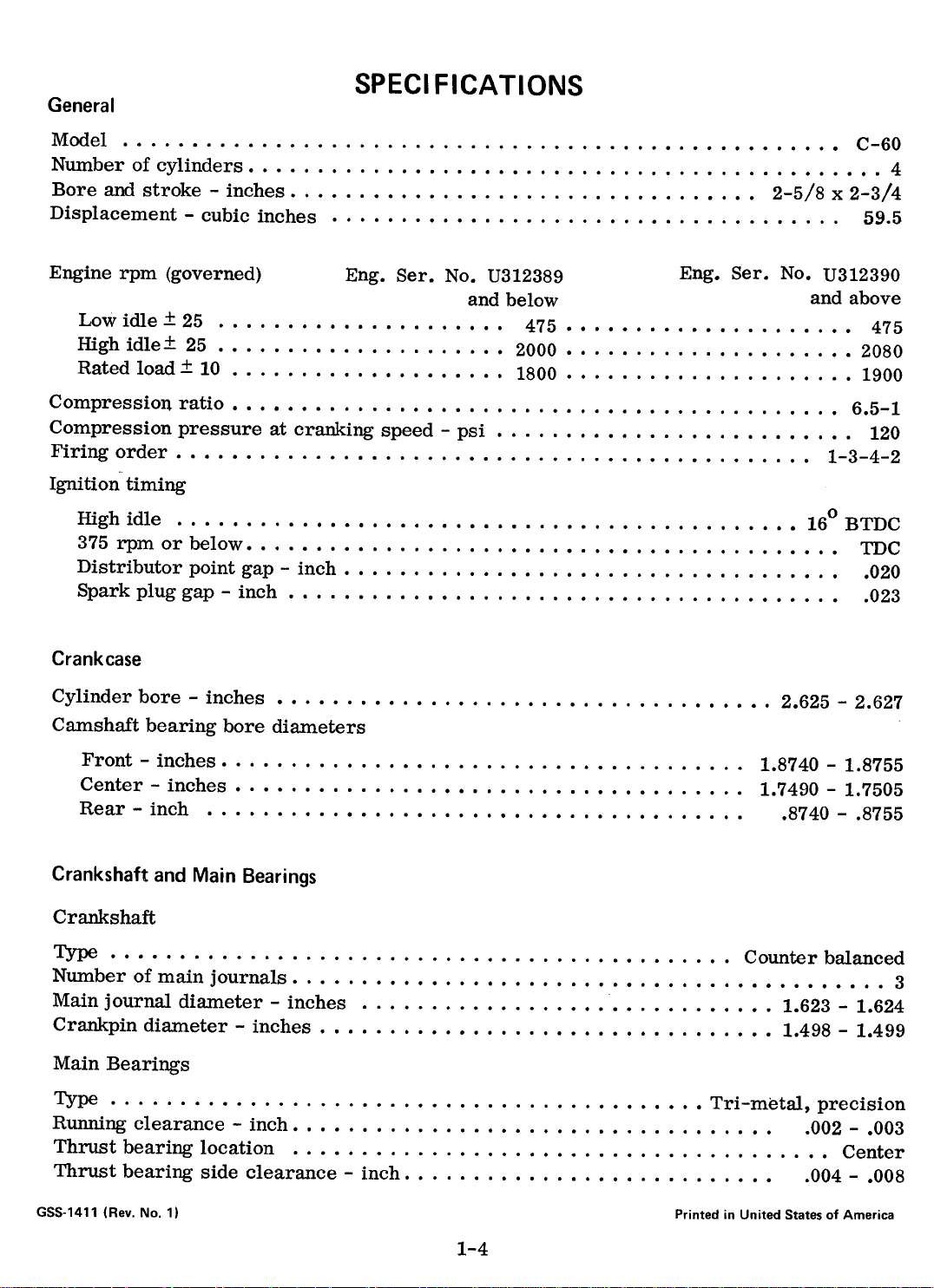
General
Model C-60
Numberofcylinders 4
Bore and stroke -inches. 2-5/8 x 2-3/4Displacement-cubic
inches 59.5
Engine rpm (governed) Eng. Sere No. U312389 Eng. Sere No. U312390
and below and above
Low idle.:t. 25 475 475
Highidle.:t.25 2000 2080
Ratedload.:t.l0 1800 1900
Compression ratio. 6.5-1
Compression pressure at cranking speed -psi. 120
Firing order. 1-3-4-2
Ignition timing
High idle 16oBTDC
.375rpmorbelow mc
Distributor point gap -inch. 020
Sparkpluggap-inch 023
Cylinder bore -inches. 2.625 -2.627
Camshaft bearing bore diameters
Front -inches. Center-inches Rear-inch
1.8740 -1.8755
1.7490 -1.7505
.8740 -.8755
Crankshaft and Main Bearings
Crankshaft
Type Counterbalanced
Number of main journals. 3
Main journal diameter -inches. 1.623 -1.624
Crankpin diameter -inches. 1.498 -1.499
Main Bearings
Type Tri-metal,precision
Running clearance -inch. 002 -.003
Thrust bearing location. Center
Thrust bearing side clearance -inch. 004 -.008
GSS-1411 (Rev. No.1)
SPECI
Crankcase
Printed in United States of America
1-4
Page 5
Bearing aD and spread
Front and rear -inches. 1.777 + .020
Center -inches. 1.777 + .002 to .015
Camshaft
Drive. Helical gear
CaIn lobe lift (total) -inch. 232 :t. .002
Diameter at bearing areas
Front-inches Center-inches Rear-inch
1.871- 1.8721.746
-1.747
.872 -.873
Thrust taken by Thrust plate
Number of bearings. 3 (bored in crankcase)
Bearing running clearance
Front and center -inch. Rear-inch
End clearance -inch.
.002 -.0045
.001 -.0035
.003 -.012
Connecting Rods
Type I-Beam
Side clearance -inch. 005 -.012
Bearing running clearance -inch. 002 -.003
Bearing type
Upper end. Bronze bushing
Lower end. Tri-metal, precision
Bearing OD and spread -inches. 1.625 + .025
Piston pin bushing (installed and bored) ill -inch. 6879 -.6882
Pistons
Type Full skirt
Material Grey iron
Overall length -inches. 2.875
Diameter -inches. 2.6230 -2.6234
* Skirt clearance, bottom -inch. 0016 -.0024
(measured at 900 from pin hole)
Number of rings per piston. 3
Piston pin hole bore -inch. 6877 -.6880
*See "Piston Fit in Bore", page 1-31.
1-5
Page 6
Pistons -Continued
Width of ring groove -inch
Topcompression Second compression. Oilcontrol
Ring clearance in groove -inch
Topcompression .
Second compression. Oilcontrol
Piston Pins
Type Diameter -inch. Length -inches. Clearance between end of pin and retainer ring -inch. Clearance in rod bushing -inch. Clearance in piston -inch.
Piston Rings
.0955 -.0965
.0955 -.0965.1880
-.1890
.0020 -.0035
.0020 -.0040
.0015 -.0030
Full floating
.6875 -.6876
2.185 -2.195
.010 -.030
.0003 -.0007
.0001- .0005
Compression
Number per piston. Type
Second..
Chrome
2
Plain
Width of ring
Top -inch. Second -inch.
.0930 -.0935
.0925 -.0935
gap
Top -inch. Second -inch.
.007 -.017
.007 -.017
Oil Control
Type Chrome, wide slotNumber
per piston. 1
Width -inch. 1860 -.1865
End gap -inch. 007 -.020
Top.
End
1-6
Page 7
Valves
Head diameter
Intake-inches 1.089-1.099
Exhaust-inch 901-.911
Face angle-degrees 45-1/2
Stem diameter
Intake-inch Exhaust-inch
-.3105.3095
-.3105
in guide
Intake-inch Exhaust-inch
Valve Seats
Seat angle -degrees. 45
Seat width
Intake-inch Exhaust-inch
Valve Guides
Length -inches. Inside diameter
Intake-inch Exhaust -inch.
.001 -.003
.0015 -.0035
3/64
3/64
1.34
.3115 -.3125.3120
-.3130
height below crankcase surface -inches.
Valve Springs
length
Intake-inches Exhaust w /0 rotocap -inches. Exhaust w/rotocap -inches.
Test length
Intake -inches. 1-1/4
Exhaust w /0 rotocap -inches. 1-1/4
Exhaust w/rotocap -inches. 1-3/16
.3095
Clearance
Installed
1-3/32
Free
1-31/321-31/32
1-7
1-7/16
Page 8
Valve Springs -Continued
Test load
Intake -pounds. 23
Exhaust w /0 rotocap -pounds. 23
Exhaust w/rotocap -pounds. 14 -16
Valve Tappets
Diameter -inch. 591- .592
Length -inches. 2.370 -2.380
Clearance in crankcase -inch. 0007 -.0032
Valve lash (engine cold) -inch. 015
Valve Timing
Intake opens -degrees. 10 before TDC
Intake closes -degrees. 45 after BDC
Exhaust opens -degrees. 45 before BDC
Exhaust closes -degrees. 5 after TDC
Cylinder Head
Boltdiameter-inch 3/8
Torque-ft.lbs. 45
Gears
Crankshaft pinion. 18 teeth
Camshalft gear. 36 teeth
Idler gear. 36 teeth
GovernQr-ignition gear. 18 teeth
Type of teeth. Helical
Backlasb -inch. 003 -.006
Idler shiaft retainer bolt tension -ft. lbs. 90
LubriC$tion System
Oil pressure at 1800 rpm -psi. 30 -35
Oil pump .
Type Gear
Drive. Direct from camshaft
Gear b;acklash -inch. 003 -.006
Timing
1-8
Numb~r of teeth
Idler gear. 13
Drilvegear 13
Page 9
lubrication System -Continued
Oil pressure valve regulating spring
Free length -inches. 2-31/32
Test length -inches. 2-15/32
Testload-pounds 9-1/2
regulating valve
Valve diameter -inch. Location
.6205 -.6215
In crankcase
Special Torques (foot pounds)
Cylinder head 45
Main bearing. 55
Connecting rod 16
Flywheel. 45
Idler gear retainer bolt. 90
Manifold 20
Spark plugs 30
Pressure
1-9
Page 10
REMOVAL
1. Disconnect the ground cable from the ~
battery, and the wires from the headlights.
2. Remove the headlights. Shut off
fuel at the fuel strainer and disconnect
the fuel line. Remove the hood and fuel
tank assembly.
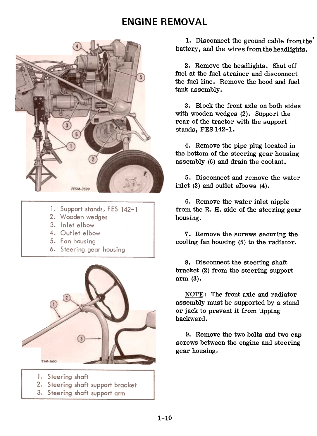
3. Block the front axle on both sides
with wooden wedges (2). Support the
rear of the tractor with the support
standst FES 142-1.
4. Remove the pipe plug located in
the bottom of the steering gear housing
assembly (6) and drain the coolant.
5. Disconnect and reDlove the vvater
inlet (3) and outlet elbovvs (4).
6. Remove the water inlet nipple
from the R. H. side of the steering gear
housing.
'? Remove the screws securing the
cooling fan housing (5) to the radiator.
8. Disconnect the steering shaft
bracket (2) from the steering support
arm (3).
~: The front axle and radiator
assembly must be supported by a stand
or jack to prevent it from tippingbackward.
9. Remove the two bolts and two cap
screws between the engine and steering
gear housing.
ENGINE
1-10
Page 11
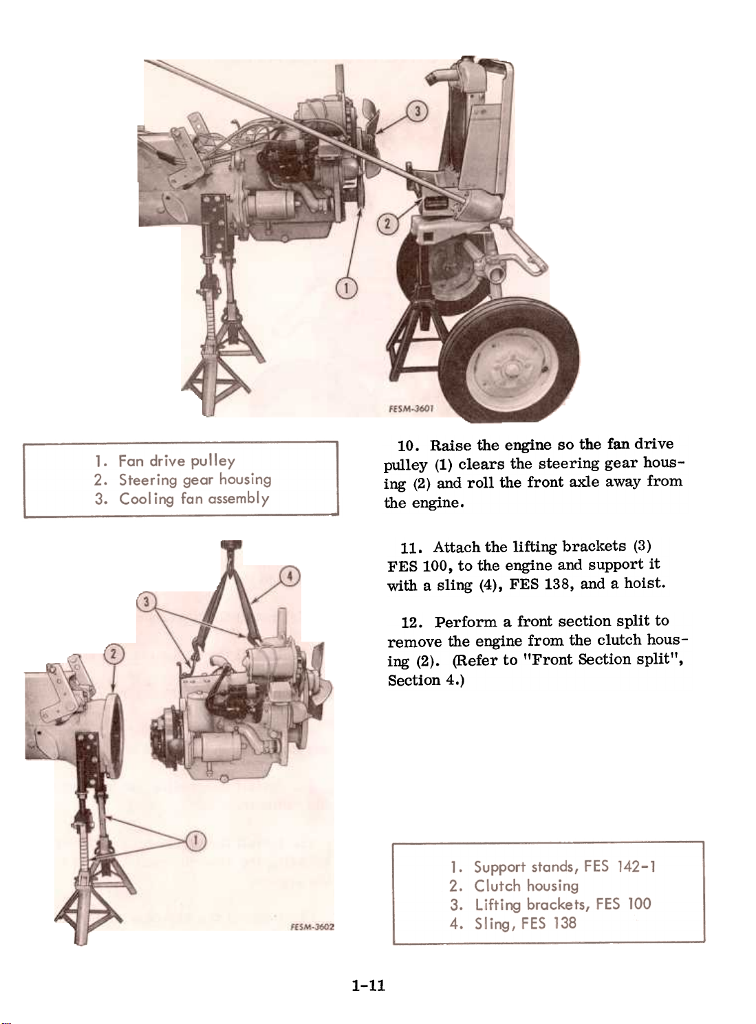
10. Raise the engine so the fan drive
pulley (1) clears the steering gear housing (2) and roll the front axle away from
the engine.
11. Attach the lifting brackets (3)
FES 100, to the engine and support it
with a sling (4), FES 138, and a hoist.
12. Perform a front section split to
remove the engine from the clutch hous-
ing (2). (Refer to "Front Section split",
Section 4.)
1-11
Page 12
ENGINE INSTALLATION
1. If the clutch assembly was removed from the engine, use a pilot shaft
to center the clutch driven disc. (Refer
to clutch "Installation", Section 5.)
2. Support the engine using the lifting
brackets, lifting sling and a hoist, and
position the engine on the clutch housing.
3. Install the two cap screws and the
nuts and bolts in the engine and clutch
housing. Tighten to 55 and 35 ft. lbs.
torque respectively.
4. Install the clutch housing cover and
secure with the nuts and bolts. Install
the clutch housing hand hole cover if it
was removed.
5. Connect the wiring harness wires
to the coil, ground, regulator and lights.
Connect the wire to the starter.
6. Using a new gasket and O-rings,
install the hydraulic manifold tubes to the
pUInp and the cylinder block assembly.
7. Install the governor control rod.
8. Install the choke control rod.
9. Install the exhaust pipe.
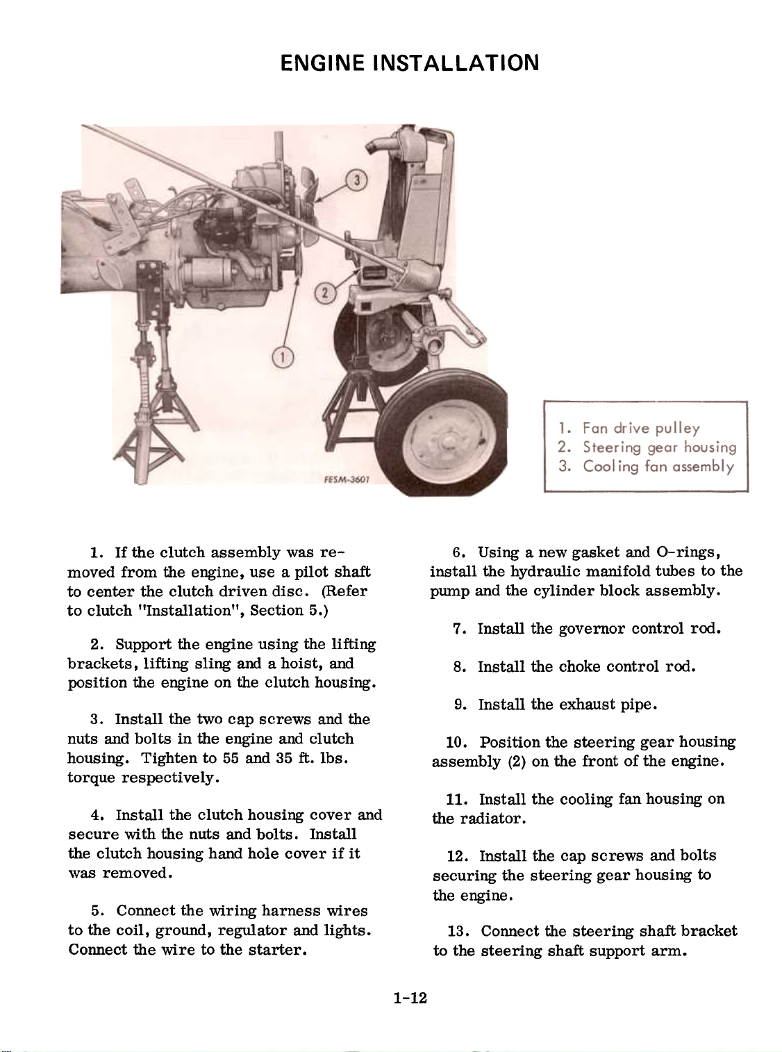
10. Position the steering gear housing
assembly (2) on the front of the engine.
11. Install the cooling fan housing on
the radiator.
12. Install the cap screws and bolts
securing the steering gear housing to
the engine.
13. Connect the steering shaft bracket
to the steering shaft support arm.
1-12
Page 13
14. Install the water inlet nipple in the
steering gear housing.
recommended coolant. (Refer to
Operator's Manual.)
15. Install and connect the water inlet
and outlet elbows and hoses.
16. Install the pipe plug in the steering
gear housing and fill the radiator with the
Removal
1. Remove the pipe plug in the bottom
of the steering gear housing and drain
the coolant.
2. Disconnect and remove the head-
lights.
17. Install the hood and fuel tank as-
sembly. Connect the fuel line to the fuelstrainer.
18. Connect the wires to the lights and
the ground wire to the battery.
HEAD
4. Remove the water outlet elbow
and hose.
Remove the spark plugs.
3. Disconnect the fuel line from the
fuel strainer. Remove the hood and fuel
tank from the tractor.
6. Remove the cylinder head capscrews,
and remove the cylinder head
and gasket from the engine.
1. Check the head and gasket for
"blow-by" or compression leaks.
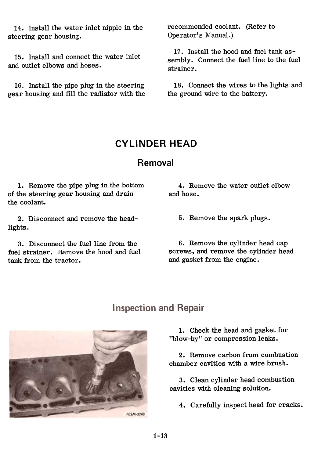
2. Remove carbon from combustion
chamber cavities with a wire brush.
3. Clean cylinder head combustion
cavities with cleaning solution.
Carefully inspect head for cracks.
CYLINDER
5.
4.
1-13
Page 14
Installation
5. Use a straight edge and inspect for
warped head, particularly in any area
which shows "blow-by. II
6. Inspect water jacket in head for an
acc~ation of rust or lime depositwhich
would affect circulation of cooling
water and cause hot spots. Clean ifnecessary.
7. Thoroughly clean the gasket surfaceto
insure proper sealing of the new gasket.
Be sure to use a ~ gasket.
1. Using a new gasket, install the cyl-
inder head on the engine.
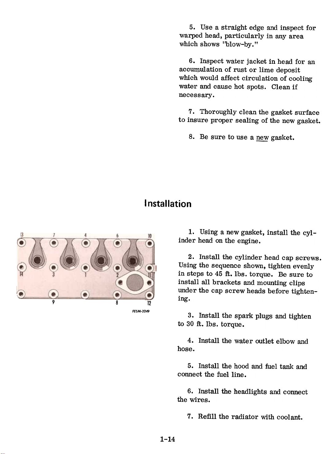
2. Install the cylinder head cap screws.
Using the sequence shown, tighten evenly
in steps to 45 ft. lbs. torque. Be sure to
install all brackets and mounting clips
under the cap screw heads before tighten-
9
8
12
FESM-3249
ing.
3. Install the spark plugs and tighten
to 30 ft. lbs. torque.
4. Install the water outlet elbow andhose.
5. Install the hood and fuel tank and
connect the fuel line.
6. Install the headlights and connectthe
wires.
8.
7.
1-14
Refill the radiator with coolant.
Page 15
Valve lash Adjusting Procedure
Following the simplified procedure in the
chart below, all valves can be adjusted
accurately. Note that the engine does notneed
to be cranked four times to positionthe
piston of each cylinder on T .D.C. All
valves are adjusted by cranking the engine
only twice.
Four valves are adjusted when the No.1
piston is at T .D.C. (compression) and the
remaining four are adjusted when the
No.4 piston is at T .D.C. (compression).
1. Remove the intake and exhaust
manifold assembly. Remove the valve
tappet cover. Clean the gasket mating
areas to insure proper sealing when re-assembled.
2. Check the entire valve assembly
for rust and dirt. Inspect for looseness
in the valve assembly and for worn or
broken valve springs.
3. Remove the spark plugs from No.1
cylinder (nearest the radiator) and No.4
cylinder.
4. Place a thumb over the No.1 spark
plug opening and slowly hand crank the
engine until an outward pressure can be
felt. Pressure indicates the piston is
moving toward top dead center of the
compression stroke.
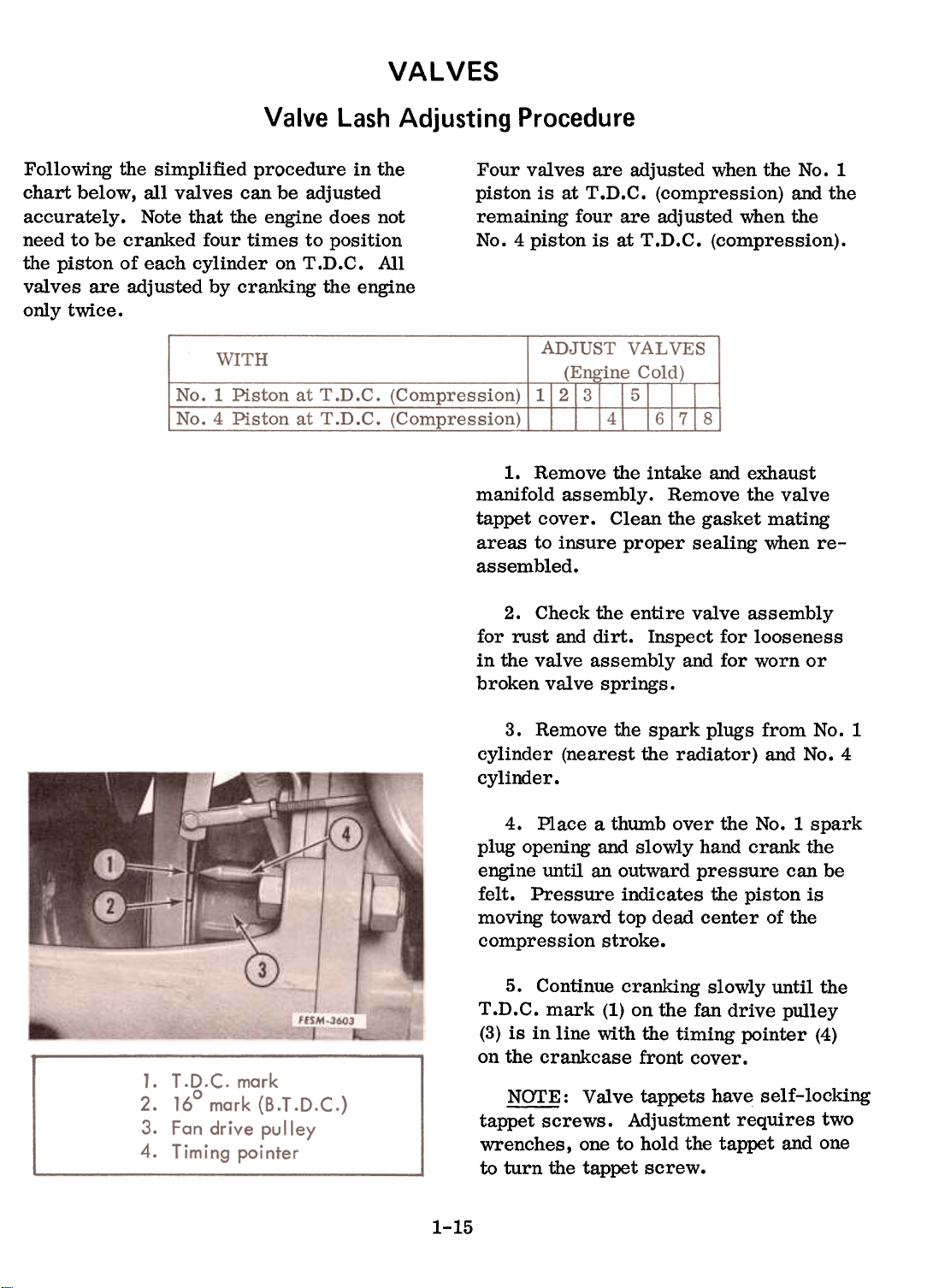
5. Continue cranking slowly until the
T .D.C. mark (1) on the fan drive pulley
(3) is in line with the timing pointer (4)
on the crankcase front cover.
~ : Valve tappets have self-locking
tappet screws. Adjustment requires two
wrenches, one to hold the tappet and one
to turn the tappet screw.
VALVES
1-15
Page 16
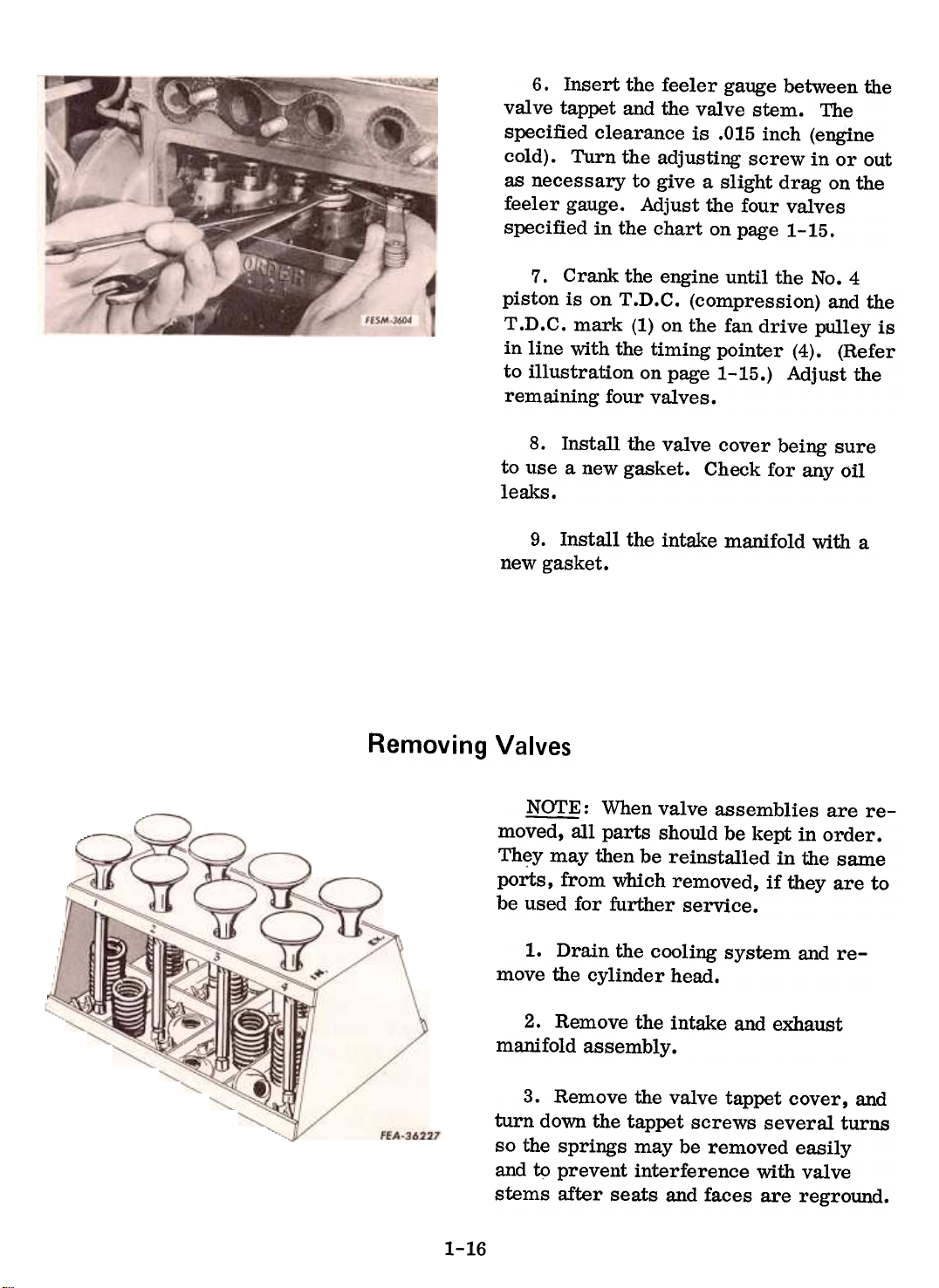
6. Insert the feeler gauge between the
valve tappet and the valve stem. The
specified clearance is .015 inch (engine
cold). Turn the adjusting screw in or out
as necessary to give a slight drag on the
feeler gauge. Adjust the four valves
specified in the chart on page 1-15.
7. Crank the engine until the No.4
piston is on T .D.C. (compression) and the
T .D.C. mark (1) on the fan drive pulley is
in line with the timing pointer (4). (Refer
to illustration on page 1-15.) Adjust the
remaining four valves.
8. Install the valve cover being sure
to use a new gasket. Check for any oilleaks.
9. Install the intake manifold with a
new gasket.
Removing Valves
~: When valve assemblies are re-
moved, all parts should be kept in order.
They may then be reinstalled in the same
ports, from which removed, if they are to
be used for further service.
1. Drain the cooling system and re-
move the cylinder head.
2. Remove the intake and exhaust
manifold assembly.
3. Remove the valve tappet cover, and
turn down the tappet screws several turns
so the springs may be removed easily
and t9 prevent interference with valve
stems after seats and faces are reground.
1-16
Page 17
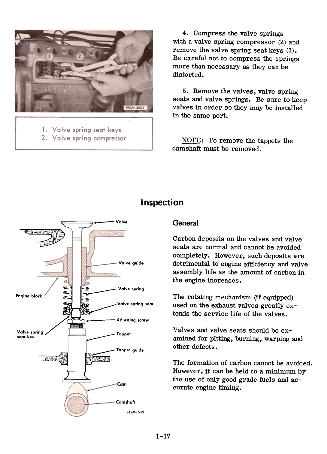
with a valve spring compressor (2) and
remove the valve spring seat keys (1).
Be careful not to compress the springs
more than necessary as they can be
distorted.
seats and valve springs. Be sure to keep
valves in order so they may be installed
in the same port.
camshaft must be removed.
Inspection
4. Compress the valve springs
5. Remove the valves, valve spring
~ : To remove the tappets the
-,~, ~ 7--Valve
':!;i~1ii,\:;~~:::::,',"""."",',':"".
Ql-J ~ Valve spring
Engine block ~ ~
Valve spring
seat key I
..(1.:);;:,;;:[,:'(!,
Valve guide
spring seat
Adjusting screw
Tappet
Tappet guide
Cam
General
Carbon deposits on the valves and valve
seats are normal and cannot be avoided
completely. However, such deposits are
detrimental to engine efficiency and valve
assembly life as the amount of carbon in
the engine increases.
The rotating mechanism (if equipped)
used on the exhaust valves greatly extends the service life of the valves.
Valves and valve seats should be examined for pitting, burning, warping and
other defects.
The formation of carbon cannot be avoided.
However, it can be held to a minimum by
the use of only good grade fuels and ac-
curate engine timing.
.--Valve
1-17
Camshaft
FfSM-32S2
Page 18
Warpage, burning and pitting of valves is
mainly directed against the exhaust valves
which are exposed to the high temperature
flow of exhaust gases. Such defects are
generally caused by valves failing to seat
tightly and evenly, permitting exhaust blowby. This, in turn, can generally be traced
to hard particles of carbon being present
on the slopes of the valve seats. It may,
however, be due to weak springs, insuf-
ficient valve clearance, or warpage and
misali.e;nment of the valve stem or guide.
Warpa~e, chiefly occurs on the valve stem
due to its exposure to heat. Out-of-round
wear occurs when the seat has been pounded
by a valve head which is not in line with its
stem or guide.
Misalignment is a result of wear, warpage,
and distortion. Wear, when accentuated by
insufficient lubrication, will eventually
create sloppy clearances with resultant
misalignment.
cylinder head bolts to the specified footpounds torque and in the sequence recommended. Valve clearances are also affected
in this manner. Thus any abnormal wear,warpage
or distortion affecting a valve
guide will destroy its function as an accurate bearing to maintain the valve head
concentric with its seat, and will prevent
leak-proof seating.
Oil and air sucked past worn intake valve
stems and guides into the combustion
chamber, cause excessive oil consumption,
form excessive carbon, and dilute fuel.
Examine the engine for signs which may
indicate the reason for the need of valve
reconditioning. Dry and rusted valve
springs are an indication that the oil passages to the valve levers may be blocked,
causing wear on the valves and guides, and
resulting in improper valve action. A de-
fective gasket under the valve cover will
permit the entrance of dirt which will
cause undue wear on the valve stems andguides
and damage to the valve springs.
Warpage of the valves, and in known ex-
treme instances, that of the crankcase, can
result from the engine overheating due to a
blocked, dirty or insufficiently filled cool-
ing system.
Most frequE;'!ntly, however, warpage of a
valve stem or a guide is due to uneven temperatures being applied along its length.
The lower part of the guide and stem is
near the combustion heat, and the upper
portions are closer to cylinder head waterpassages.
Valve materials are carefully
chosen to withstand such varying temperatures. However, an engine that is allowed
to operate continually in an overheated con-
dition is definitely open to valve stem and
guide distortion and warpage. Distortion
can also be caused by failure to tighten
Valves
1. Remove all carbon from the valve
head and stem. Valve stems should be
lightly polished with an extremely fine
abrasive cloth sufficiently to remove the
carbon deposits only. Because of the
nature of the valve deposits, solvent cleaning ordinarily will not remove all the deposits from the valves. Wire brushes will
do this job satisfactorily, but only brasswire
brushes should be used since steel
brushes may scratch the surface. Such
scratches are likely to cause localized
stresses in an operating valve and may
eventually result in fatigue fractures of
the valve. For similar reasons the use of
coarse emery paper should be avoided.
1-18
Page 19
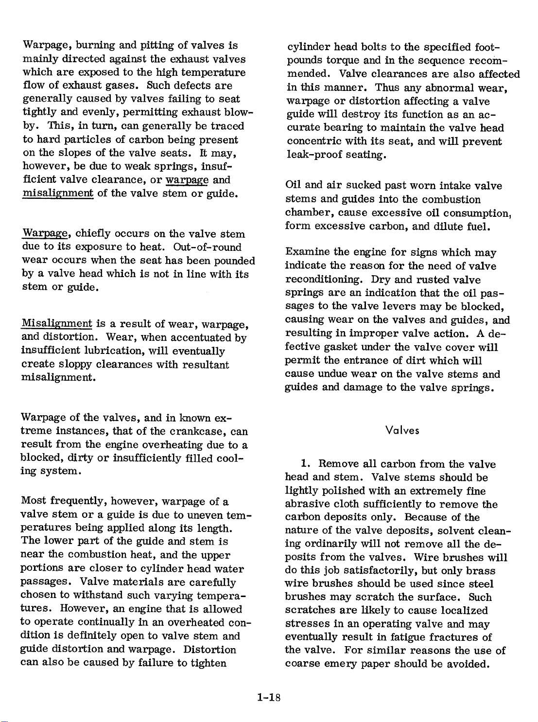
2. Inspect each valve. See that the
stem is not worn excessively and that the
head is not burned or warped. Check the
WRONG
CORRECT
WRONG
FEA-64460
grooves in the stem to see that they have
not lost the shoulders through wear, which
prevents the valve seat retainer keys from
fitting snugly.
3. All valves having bent, worn, warped
or seriously pitted stems should be re-
placed. Replace any valve that cannot be
satisfactorily refaced with a definite mar-
gin maintained. The amount of grinding
necessary to true the valve face is a def-
inite indication of the valve head warpage
from the axis or centerline of its stem.
With excessive warpage, a knife edge will be
ground on part or all of the valve head due
to the considerable amount of metal that
must be removed to completely reface.
Maximum heaviness in a valve head is required for strength and to provide as large
an area as possible for heat dissipation.
Knife edge valves lead to breakage and
warpage.
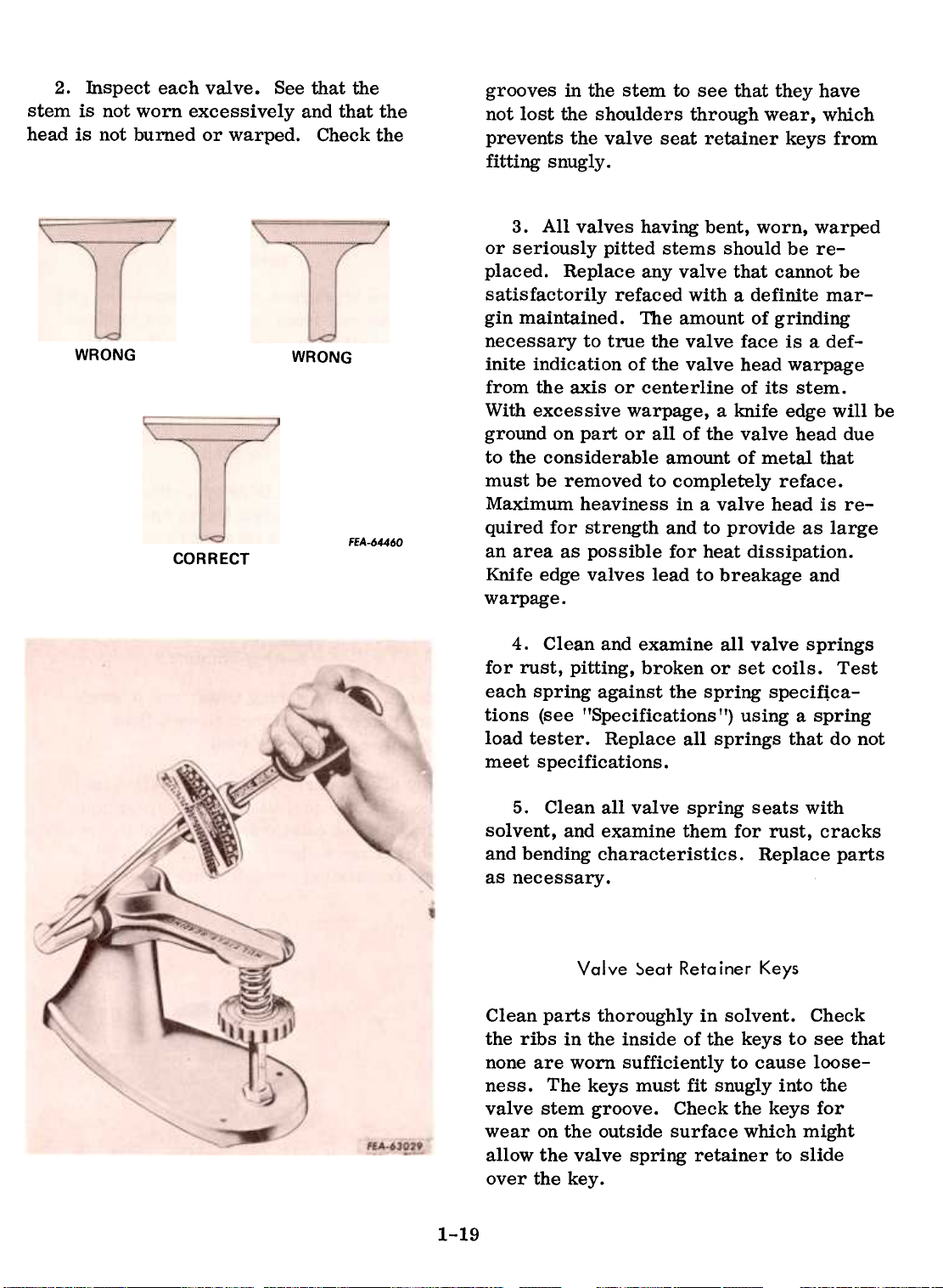
4. Clean and examine all valve springs
for rust, pitting, broken or set coils. Test
each spring against the spring specif\ca-
tions (see "Specifications II) using a spring
load tester. Replace all springs that do not
meet specifications.
5. Clean all valve spring seats with
solvent, and examine them for rust, cracks
and bending characteristics. Replace parts
as necessary.
Valve ::>eat Retainer Keys
Clean parts thoroughly in solvent. Check
the ribs in the inside of the keys to see that
none are worn sufficiently to cause loose-
ness. The keys must fit snugly into the
valve stem groove. Check the keys for
wear on the outside surface which might
allow the valve spring retainer to slide
over the key.
1-19
Page 20
Valve Guides
Clean the bores of the valve guides, using awire
rifle brush and solvent. Blowout all
carbon with compressed air. Position a
light at the bottom of the guide bore, and
examine the walls for burning, cracking and
signs of excessive wear. Check the inside
diameter of the guide bore at several points
around its circumference and along its
length. Replace any guides considered un-
serviceable or that appear close to a
serviceable borderline.
~: All valve reconditioning equip-
ment requires the installation of a pilot in
the valve guide to produce a seat concentric
with the guide bore. For this reason the
guides must be clean and meet the engine
specifications before the valve seats can be
reconditioned.
Valve Seats
Remove all carbon and any remaining gas-
ket material from the crankcase surface.
Inspect all valve seats for cracks. Re-
move the carbon from the valve seat recesses or counterbores.
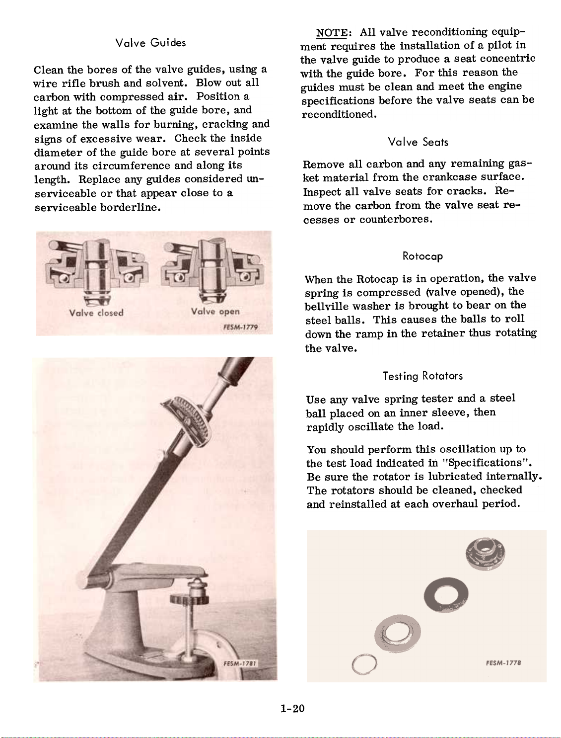
Rotocap
When the Rotocap is in operation, the valve
spring is compressed (valve opened), the
bellville washer is brought to bear on the
steel balls. This causes the balls to roll
down the ramp in the retainer thus rotating
the valve.
Testing Rotators
Use any valve spring tester and a steel
ball placed on an inner sleeve, then
rapidly oscillate the load.
You should perform this oscillation up tothe
test load indicated in "Specifications".
Be sure the rotator is lubricated internally.
The rotators should be cleaned, checked
and reinstalled at each overhaul period.
1-20
Page 21
Observing the operation of the valves prior
to tear-down of the engine is beneficial in
preventing unnecessary checking of worn
rotators. Mark the valves with a pencil as
movement is relatively slight.
Reconditioning
Valve Guides
1. Press the g11ides from the crankcase.
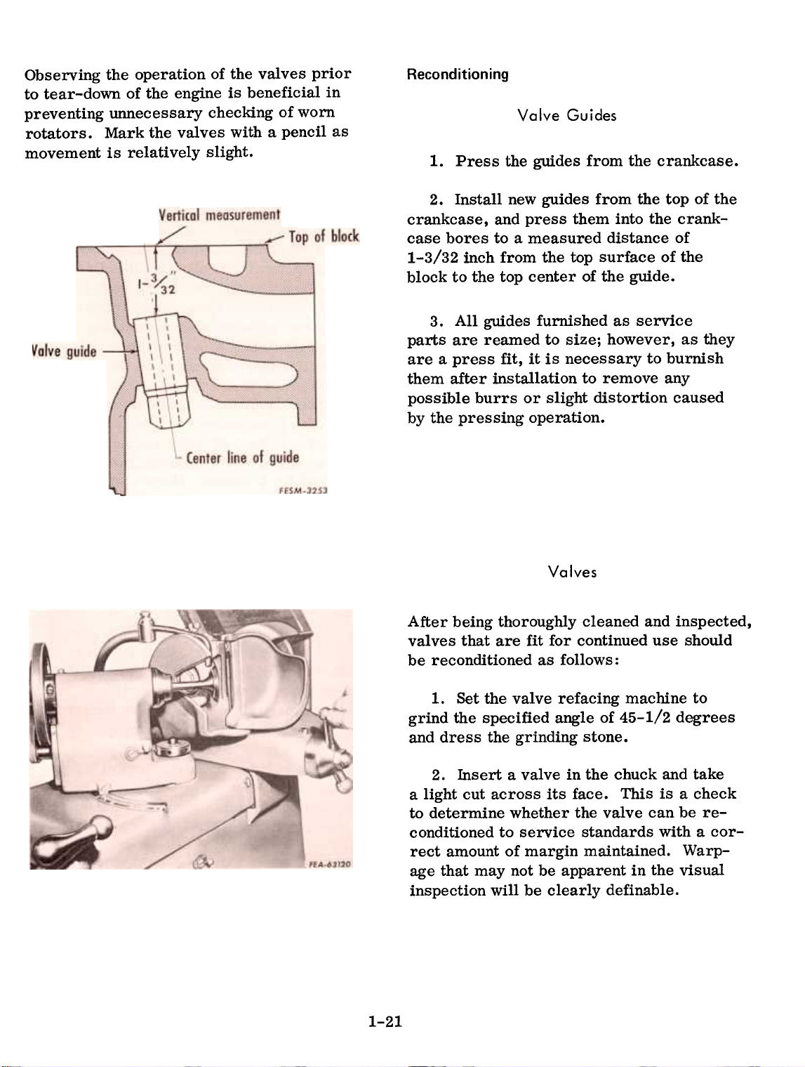
2. Install new guides from the top of the
crankcase, and press them into the crankcase bores to a measured distance of
1-3/32 inch from the top surface of the
block to the top center of the guide.
3. All guides furnished as service
parts are reamed to size; however, as they
are a press fit, it is necessary to burnish
them after installation to remove any
possible burrs or slight distortion caused
by the pressing operation.
Valves
After being thoroughly cleaned and inspected,
valves that are fit for continued use should
be reconditioned as follows:
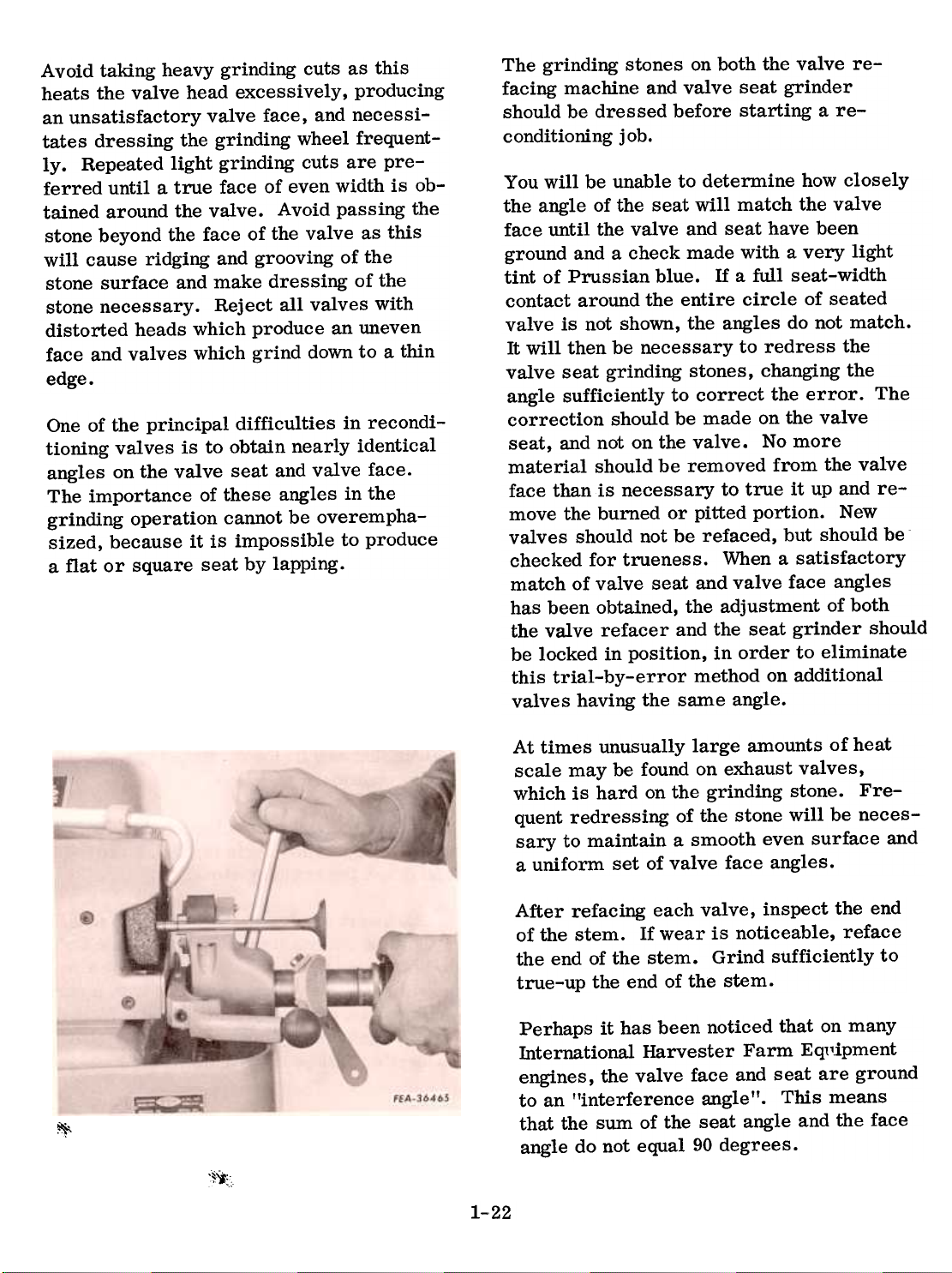
1. Set the valve refacing machine to
grind the specified angle of 45-1/2 degrees
and dress the grinding stone.
2. Insert a valve in the chuck and take
a light cut across its face. This is a check
to determine whether the valve can be reconditioned to service standards with a cor-
rect amount of margin maintained. Warp-
age that may not be apparent in the visual
inspection will be clearly definable.
1-21
Page 22
Avoid taldng heavy grinding cuts as this
heats the valve head excessively, producing
an unsatisfactory valve face, and necessi-
tates dressing the grinding wheel frequent-
ly. Repeated light grinding cuts are preferred until a true face of even width is obtained around the valve. Avoid passing the
stone beyond the face of the valve as this
will cause ridging and grooving of the
stone surface and make dressing of the
stone necessary. Reject all valves with
distorted heads which produce an uneven
face and valves which grind down to a thin
edge.
One of the principal difficulties in recondi-
tioning valves is to obtain nearly identical
angles on the valve seat and valve face.
The importance of these angles in the
grinding operation cannot be overempha-
sized, because it is impossible to produce
a flat or square seat by lapping.
The grinding stones on both the valve re-
facing machine and valve seat grinder
should be dressed before starting a re-
conditioning job.
You will be unable to determine how closely
the angle of the seat will match the valve
face until the valve and seat have been
ground and a check made with a very light
tint of Prussian blue. If a full seat-width
contact around the entire circle of seated
valve is not shown, the angles do not match.
It will then be necessary to redress the
valve seat grinding stones, changing the
angle sufficiently to correct the error. The
correction should be made on the valve
seat, and not on the valve. No more
material should be removed from the valve
face than.is necessary to true it up and remove the burned or pitted portion. New
valves should not be refaced, but should be
checked for trueness. When a satisfactory
match of valve seat and valve face angles
has been obtained, the adjustment of both
the valve refacer and the seat grinder should
be locked in position, in order to eliminate
this trial-by-error method on additional
valves having the same angle.
At times unusually large amounts of heat
scale may be found on exhaust valves,
which is hard on the grinding stone. Fre-
quent redressing of the stone will be neces-
sary to maintain a smooth even surface and
a uniform set of valve face angles.
After refacing each valve, inspect the end
of the stem. If wear is noticeable, reface
the end of the stem. Grind sufficiently to
true-up the end of the stem.
Perhaps it has been noticed that on many
International Harvester Farm Eq11ipment
engines, the valve face and seat are ground
to an "interference angle". This means
that the sum of the seat angle and the face
angle do not equal 90 degrees.
1-22
~;~'i":,
Page 23
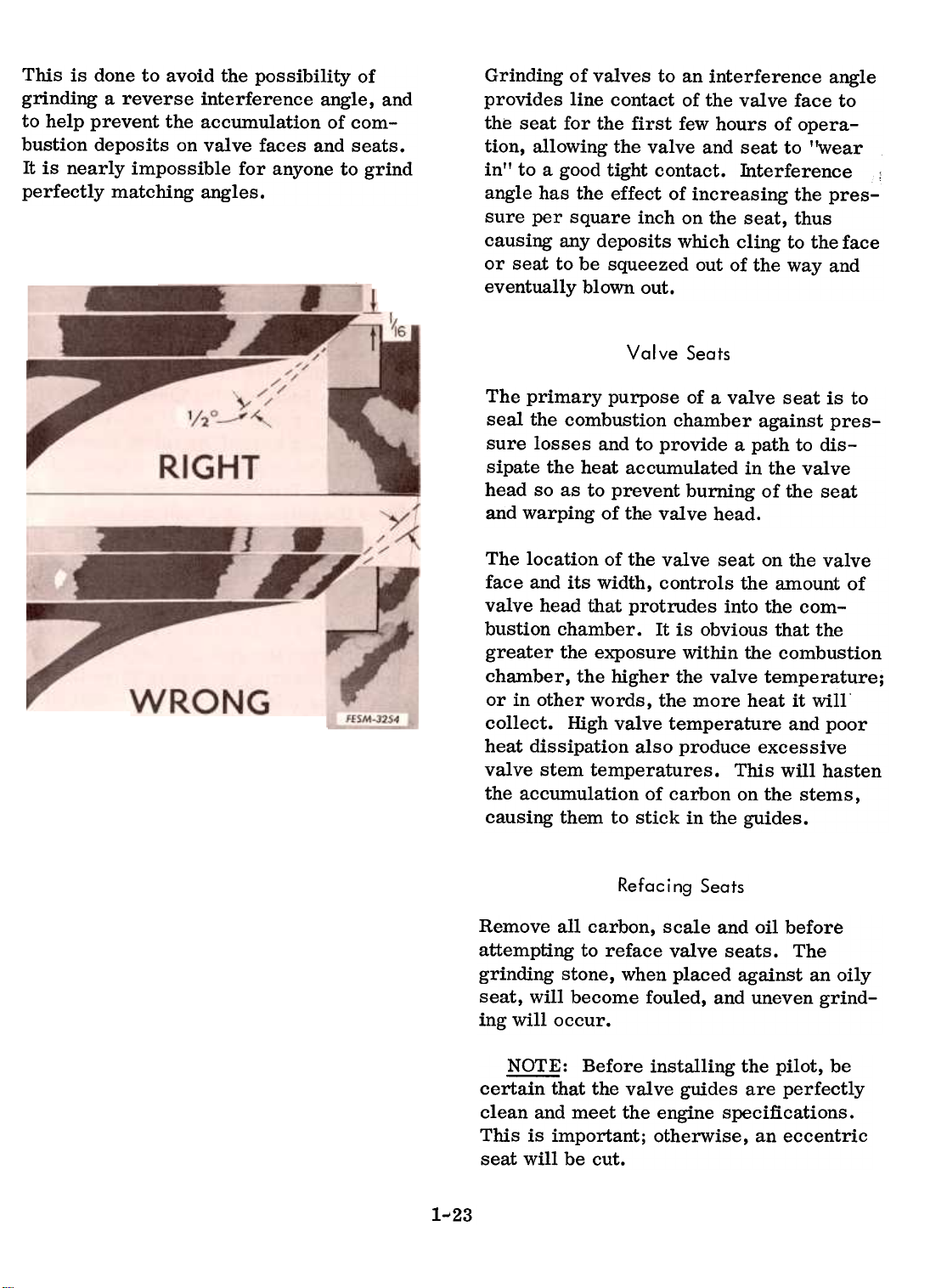
This is done to avoid the possibility of
grinding a reverse interference angle, and
to help prevent the accumulation of combustion deposits on valve faces and seats.
It is nearly impossible for anyone to grind
perfectly matching angles.
Grinding of valves to an interference angle
provides line contact of the valve face to
the seat for the first few hours of operation, allowing the valve and seat to "wear
in" to a good tight contact. Interference
angle has the effect of increasing the pres-
sure per square inch on the seat, thus
causing any deposits which cling to the face
or seat to be squeezed out of the way and
eventually blown out.
Seats
The primary purpose of a valve seat is to
seal the combustion chamber against pres-
sure losses and to provide a path to dis-
sipate the heat accumulated in the valve
head so as to prevent burning of the seat
and warping of the valve head.
The location of the valve seat on the valve
face and its width, controls the amount ofvalve
head that protrudes into the combustion chamber. It is obvious that the
greater the exposure within the combustion
chamber, the higher the valve temperature;
or in other words, the more heat it will'
collect. High valve temperature and poor
heat dissipation also produce excessivevalve
stem temperatures. This will hastenthe
accumulation of carbon on the stems,
causing them to stick in the guides.
Valve
1-'23
Refacing Seats
Remove all carbon, scale and oil before
attempting to reface valve seats. The
grinding stone, when placed against an oily
seat, will become fouled, and uneven grind-
ing will occur.
~: Before installing the pilot, be
certain that the valve guides are perfectly
clean and meet the engine specifications.
This is important; otherwise, an eccentric
seat will be cut.
Page 24

the stone to the correct angle.
Lightly lubricate and install the pilot of the
correct size into the valve guide bore.
to clear away grinding dust. Grind the
seat sufficiently to provide an even,
smooth surface.
Lower the grinder head over the pilot
shank until the stone just clears the valveseat.
Turn on the power and very gently
allow the stone to contact the valve seat.
Very little pressure other than the normal
weight of the stone should be used. Sudden
hard pressure can cause cocking of the
pilot in the guide and result in eccentric
grinding. Raise the stone frequently from
the valve seat to prevent overheating and
Correct Seat
Seat too wide
Check the seat concentricity, roundness
and valve face contact using Prussianblue.
Spread an extremely thin film of
this blue on the valve face and insert the
valve into its guide. With pressure on the
exact center of the valve head, make a
quarter turn rotation in the seat. Remove
the valve and inspect the impression made
upon the seat by the transfer of blueing,
and upon the valve face by the removal of
blueing. Check several times to guarantee
that no error was made. If a full seat-
width contact around the entire circle of
seated valve is not shown, the angles do
not match. It will then be necessary to re-
dress the valve seat grinding stones,
changing the angle sufficiently to correct
the error. The correction should be made
on the valve seat, and not on the valve.
The location of the area of contact between
the valve and the seat is a very important
factor in securing maximum valve life.
Seating the valve with the sharp edge of the
seat not contacting the valve face is un-
desirable. This sharp edge tends to break
off face deposits which may lead to valve
failure.
Dress
Seat too narrow
FEA-63042
FESM-32SS
Similarly, the location of the upper line of
contact well below the top of the valve face,
is also undesirable because a large overhang prevents rapid cooling of the outer
edge of the valve.
After grinding the seats it may be found
that the seats are considerably wider than
the specified width of 3/64 inch. Valve
seats that are too wide may be narrowed
by grinding down the top edge of the seat
with a stone mounted on the grinder head.
The stone must be a smaller angle than
the valve seat (1~ preferably).
1-24
Page 25

Reassembly
1. Coat the valve stems with engine
oil and insert the intake and exhaust
valves into their original positions.
2. Install the valve springs and valve
spring seats. Compress the valve springs
and install the valve seat retainer keys.
Release the springs and remove the valvecompressor.
4. Install the valve tappet cover using
a new gasket.
5. Install the intake and exhaust mani-
fold assembly using a new gasket. Tighten
the nuts evenly in steps to 20 ft. lbs.torque.
6. Install the cylinder head. Refer to
3. Adjust the valve tappets. Refer to
page 1-15.
page 1-14.
7. Refill the radiator with coolant.
CONNECTING RODS, PISTONS AND PISTON RINGS
General
Connecting Rods
The connecting rods serve as the links be-
tween the pistons and the crankshaft. The
surfaces of the rods must be kept free of
scoring and dents because of the high
stresses under which they function. The
rod has a bushing at each end, the one at
the upper end is a bushing for the piston
pin which anchors it to the piston. The
bearing at the crankshaft or lower end is
inserted in two halves which fit around
the crankshaft and are secured by a bear-
ing cap. The bearing cap is furnished
only with its connecting rod.
1-25
The lower bearings used in these engines
are the replaceable insert type and insure correct running clearances when
they are properly installed. This is possible without boring. reaming, scraping
or using shims. The three important
fundamentals on bearings and bearing
fitting are "bearing crush," "bearing
spread," and "bearing clearance." An explanation of these will be covered later.
Page 26

Pistons
The piston is one of the most important
units in the engine, and its condition has
much to do with the performance of the
engine. Its function is to receive the
force of the combustion pressure and
transmit it to the connecting rod and
crankshaft. The escape of combustion
pressure past the piston is prevented by
the piston rings. The fit of the piston and
rings in the sleeve must be close enough
to prevent the escape of combustion gases
but must be free enough to keep friction
to its working minimum.
Piston Rings
The pistons are fitted with three piston
rings. One oil regulating ring is fitted to
each piston. The oil regulating ring pro-
vides an even circulation of lubricating
oil and, therefore, an allover lubricating
and cooling action for the piston and
crankcase cylinder. Excess oil is wiped
by the rings, back down to the crankcase.
The remaining rings are compression
rings. Rings should be installed on a
piston so that the gaps are 90 degrees
from the thrust side of the piston and 180
degrees from one gap to another.
Piston Pins
The piston pin is made of steel and is
cylindrical in shape. Its purpose is to
anchor the piston to the connecting rod.
The pin is retained in the piston by re-
tainer rings that lock into grooves of the
piston pin bore. The pin is allowed to
float in its bushing in the upper end of the
rod. It is usually necessary to heat the
piston in order to remove the pin.
Cylinder
ridge
Worn rings
fit ridge
New ring
interference
Removal
1. Remove the cylinder head. (Refer
to page 1-13.)
2. Remove the drain plug and drain
the engine lubricating oil from the crankcase oil pan. Replace the drain plug.
3. Remove the cap screws securing
the oil pan, and remove the oil pan and
gasket.
IMPORTANT: Before proceeding with
piston and connecting rod removal, the
ridge, existing on the cylinder wall at the
upper end of the ring travel, must be removed by using a ridge reamer. This
prevents damage to the piston ring lands
during removal of pistons, and prevents
damage to new top piston rings after the
installation of new rings.
FESM-3257
1-26
>!~t;Z;-..,
",..~"..
\!:':!:!:
Page 27

4. Remove the oil pump screen and
tube assembly.
5. Remove the connecting rod bearing
cap nuts. Remove the bearing cap. Be
sure that each bearing and cap can be
identified with the connecting rod from
which it was removed. Each connecting
rod should be found numbered on the carn-
shaft side of the rod, indicating its position in the engine.
IMPORTANT: Pistons must be handled
carefully to avoid damage and knocking
out-of-round or alignment. When removing a piston from the crankcase, do
not allow the skirt of the piston to strike
the crankcase or connecting rod. Mark
the pistons so they can be installed in the
same position and cylinder from which
they were removed. The dome of the
piston is stamped with an arrow, indi-
cating its position when properly installed.
6. Push the connecting rod and piston
assembly to the top and lift out from the
crankcase. Replace the cap on the connecting rod to avoid damage.
Disassembly
7. Crank the engine by hand to make
each rod and cap accessible and remove
all pistons and connecting rods in the
same manner.
1. Remove the piston rings with a
piston ring expander. Remove the top
ring first and the remaining rings inorder.
2. Remove the piston pin retainer
rings.
3. Remove the piston pins from the
pistons. As an aid in removing the pin,
heat the piston in hot-to-boiling water
and then remove the pin, being careful
not to damage the piston.
1-27
Page 28

nspection and Repair
1. Wash all parts in a cleaning solvent.
Clean the carbon from the piston ring
grooves with a broken ring or ring groovecleaner.
2. Inspect the connecting rods, caps,
bearing shells and pin bushings as
follows:
(a) All connecting rod bearings and
piston pin bushings should be replaced in
a major overhaul.
(b) Test rods for alignment. Rods
only slightly misaligned can be straightened
using the proper equipment. Badly twisted
or bent rods must be replaced.
3. Inspect the pistons for cracks,
breaks or scores.
4. Measure the piston skirt at right
angles to the pin to determine if it is
worn excessively; replace if necessary.
The specified piston diameter is 2.6230
to 2.6234 inches.
~: On a used piston, it will probably be found that the piston ring side
clearances tend to increase toward the
top of the piston due to the higher operating temperature prevalent at this point.
\Vhen this side clearance becomes excessive, the piston will have to be replaced.
5. Measure the crankcase cylinder
bores for excessive wear. The specified
bore ill is 2.625 to 2.627 inches. Replace-
ment pistons are available in .020 and
.040 inch oversizes.
6. Inspect the piston pins for wear; if
wear is perceptible, replace pins. Replace piston pins showing signs of cor-
rosion or etching. Specified piston pin
diameter is .6875 to .6876 inch.
7. Inspect the connecting rod bushings
for scratches and burrs. Replace ifnecessary.
8. Connecting rod bolts must be
cleaned of all foreign matter including
the anti -rust materials that may be caked
in the threads. This is also true of the
connecting rod bolt nuts.
A good method of checking to determine
thread condition is to turn the connecting
rod bolt (threads lubricated mth a light
engine oil) all the way into a standard nut
mth the fingers. If the bolt runs in relatively free mthout sticking or mthout the
need for applying more than a very light
(2-4 foot-pounds) wrench effort, the bolt
is satisfactory for use.
9. Rings should be checked also for
the specified side clearance by measuring
the clearance between the piston ring and
the piston ring land as shown.
1-28
I
Page 29

10. Inspect the piston rings for damage.
Faulty rings cannot always be detected by
the eye. Engine performance and irregu-
larities such as excessive oil consumption
must be taken into consideration. Where-
ever there is doubt as to the serviceability
of the piston rings, it is advisable to replace such parts.
11. Insert each ring into the cylinder
bore for that piston. Force them squarely
down inside the sleeve or cylinder bore.
Position a feeler gauge between the ends of
the ring, and compare the existing gap
against the specified gap. If it is neces-
sary to remove material from the ring
ends because the end gap is too close,
clamp a mill file in a vise, hold the ring in
proper alignment and dress off the ends
squarely to obtain the desired gap.
12. Inspect the "windows" of the oil
regulating ring and piston for blocked oil-
ways. Failure to keep the oilways clear
will result in uneven lubrication and "hot-
spots" of the piston and cylinder sleeve.
All rings should fit loosely in the piston
grooves without binding.
13. Place connecting rods in an arbor
press and press old piston pin bushings
from the connecting rods.
14. Align the new piston pin bushing on
the connecting rod so that the oil hole in
the bushing will match with the oil hole in
the connecting rod. Press the bushing into
the rod.
15. Press the bushing into place in the
connecting rod and then ream to provide
the specified piston pin clearance of .0003
to .0007 inch.
1-29
Page 30

Reassembly
1. Before assembling the piston and
connecting rod, check the fit of the piston
pin in the piston for proper end clearance
as follows:
(d) Using a feeler gauge, in the gap
between the piston pin and the retainer
ring, check for end clearance. Specified
end clearance is .010 to .030 inch.
(e) Remove the retainer rings and
proceed with the assembly as follows:
(a) Prepare the piston and the pin
for assembly as outlined in Step 2.
(b) Push the pin into the piston and
install a retainer ring at each side of the
piston.
(c) Push one end of the piston pin
until it stops against the retainer ring on
the opposite side of the piston.
Top ring
Inner groove up
Lower ring
Outer groove down
Oil control
ring
~: When assembling the pistons tothe
rods, the front of the piston will be
indicated by an arrow.
2. With the piston pin at room temperature (700) and generously coated with clean
engine lubricating oil, and the piston heated
in hot water to approximately 1500F the piston pin can be entered into one boss of the
piston by pushing with the hand. While the
piston is hot, quickly and correctly position
the connecting rod inside the piston, align
the bushing in the rod bore with the piston
pin holes in the piston and push the piston
pin completely into position. Thoroughly
dry the piston with compressed air.
3. Install a retainer ring in the groove
at each side of the piston to secure the
piston pin.
FESM-326 I
4. Using a piston ring expandert install
the ringst oil control ring firstt into the
grooves of the pistons.
Position the ring gaps 90 degrees from the
thrust side of the piston (in line with the
piston pin bore) and 180 degrees from one
gap to another.
Be sure the compression rings are installed with their grooves positioned as
shown.
1-30
Page 31

Piston Fit in Bore
Specified piston-to-bore clearance is .0016
to .0024 inch and can be determined using
a 1/2 inch wide feeler gauge and a spring-type
tension scale (FES 108).
The thickness of the feeler gauge that canbe
removed with a 2 to 8 pound pull repre-
sents the piston-to-bore clearance as out-lined
in the "Piston Clearance Chart."Clearances
should conform to specifications.
The chart shows the relationship between
the feeler gauge thickness and pounds pull
in measuring piston-to-bore clearance.
Note that with a given feeler gauge thick-
ness the actual clearance is less than the
feeler gauge used when the pound pull is
towards the high side of the pound pull
range. This is especially true with the
thinner feeler gauges.
determine piston-to-bore clearanceproceed
as follows:
1. Select a feeler gauge (free of dents
or burrs) of one of the thicknesses listed
in the chart. Position the feeler gauge inthe
cylinder bore so that it extends theentire
length of the piston 900 from the
piston pin location.
Pull
inLbs.
2
4
6
8
PISTON CLEARANCE CHART
Feeler Gauge Thickness
.00151.002
.003
.00351.004
.0045
Clearance in Inches
.00161.00221.00331.00391.00441.005
.00131.00181.00291.00351.004
.001
.0046
2. Invert the piston and install it in the
bore so that the end of the piston is about
1-1/2 inches below the top of the cylinder
block and the piston pin is parallel to the
crankshaft axis.
3. Hold the piston and slowly pull the
scale in a strai~ht line with the feeler
gauge, noting the pull required to remove
the feeler gauge. Check three times and
record the average of the three readings
obtained. Do not bend or kink the feeler
gauge.
4. Refer to the chart to determine the
actual clearance. The clearance is shownwhere
the horizontal column indicatingpounds
pull and the vertical column indi-cating
the thickness of the feeler gaugeused
intersect.
EXAMPL~: If a .003 inch feeler gaugeis
used and it takes 8 pounds pull to removethe
feeler gauge, the clearance is .0023 inch.
To
.00151.00261.00311.00361.0042
.0008/.00131.0023/.00281.00331.00381-31
Page 32

5. Repeat step 3 with the piston at right
angles to the crankshaft axis. Determine
the clearance as instructed in step 4.
6. Measuring piston-to-bore clearance
with the piston pin parallel and at right
angles to the crankshaft axis will reflect
any "out of round" in the bore.
Bearing Fitting Procedure
C_AUTION: Bearings or bearing caps
must not be filed, lapped or modified in any
manner to reduce journal-to-bearing clearance. Premature bearing failure will re-
sult from attempts to reduce journal-to-
bearing running clearances. While such
methods will make a tighter fit at the top
and bottom of the bearing, it will result in
an out-of-round bore and distortion of the
bearing shell. New bearing shells will
have to be installed eventually and addi-
tional problems will be encountered. Such
modification alters the engineered fit of
the bearing shells in their bores and de-
stroys the desired "crush".
1. When installing precision type bear-
ings, it is important that the bearing shells
fit tightly in the rod or crankcase bore. To
accomplish this, the diameter of the bearing at right angles to the parting line is
slightly larger than the actual diameter of
the bore onto which the bearing will be
assembled. When the bearing cap is drawn
up tight the bearing is compressed, assur-
ing a positive contact between the bearing
back and bore. The increased bearing
diameter is called "bearing crush".
1. Bearing locking tangs
Be certain the bearings are fully seated
and the locking tangs (1) on the bearings
fit into the recesses.
2. To assemble the bearings with the
correct "bearing crush," tighten the clamping bolts alternately and evenly to the
specified torque with a torque wrench.
1-32
Page 33

SOFT MALLET (STRIKE LIGHTLY
AND SQUARELY)
BEARING
FEA.63050
~:;;:;;~~~
WOOD BLOCK
3. Main and connecting rod bearings
are designed with the "spread" (width
across the open ends) slightly greater than
the diameter of the crankcase bore or
connecting rod bore into which they are to
be assembled. For example, the width
across the open ends of the connecting rod
bearing not in place is approximately .025
inch more than when the bearing is in position in the rod. This condition causes the
bearing to fit snugly in the rod bore and the
bearing must be "snapped" or lightly
forced into its seat.
Rough handling in shipment, storage, or
normal use in an engine, may cause the
bearing spread to be increased or decreased from the specified width. Bearing
spread should therefore be carefully meas-
ured and corrected as necessary before
installation in an engine. Bearing spread
can be safely adjusted as follows if care
and judgment are exercised.
(a) EXCESSIVE SPREAD: If meas-
urement of bearing indicates that dimension
"A " is excessive, place bearing on a wood
block and strike the side lightly and square-
ly with a soft mallet. Recheck measurement
and, if necessary, continue until correct
width is obtained.
~
DECREASING SPREAD
(b) INSUFFICIENT SPREAD: If
measurement of bearing indicates insufficient spread, place bearing on a wood
block and strike the back of the bearing
lightly and squarely with a soft mallet.
Recheck measurement and if necessary
continue until correct width is obtained.
1- 33
Page 34

4. BEARING CLEARANCE: When in-
stalling bearings in an engine, the proper
clearance between bearing surface should
be checked closely. Specified bearing
clearance is .002 to .003 inch. To get an
accurate measurement of this clearance,
the IIPlastigage II method, or virgin lead,
(a) Remove bearing cap and wipe
bearing surface and exposed half of crank-
shaft journal free of oil.
(b) Place a piece of "Plastigage" the
full width of bearing insert.
can be used. The following instructions
can be used when measuring with
"Plastigage":
(c) Reinstall the bearing cap and
tighten the self-locking cap screws to 16
foot-pounds torque.
(d) Remove the bearing cap. The
flattened plastic material will be found adhering to either the bearing shell or the
crankshaft.
(e) To determine the bearing clearance, compare the width of the flattened
plastic material at its widest point with
the graduations on the envelope. The number within the graduation on the envelope
indicates the clearance in thousandths of an
inch.
(f) If using virgin lead, carefully remove the flattened lead and measure its
thickness with a micrometer.
~: Do not turn crankshaft duringthe
above procedure.
Should the readings not fall within the specified limits, and the torque wrench is known
to be accurate in its measurement, remove
the bearing from the connecting rod and
replace it with a new one. However, with
the precision bearings used, no difficulty
should be encountered providing the crank-
shaft and/or connecting rod are in proper
condition.
1-34
Page 35

Installation
I. Cyl indor numbor toward camshaft I
NOTE: When reinstalling a piston and
connecting rod assembly, install the assembly in the same cylinder bore and in
the same position from which it was removed. Connecting rods are stamped with
the cylinder number on one side of the rod
and on the same side of the bearing cap,
No.1 starting at the front end of the en-
gine. Be sure to install the numbered
side of both the rod and bearing cap so
both are on the camshaft side of the
engine.
1. Generously coat the piston ring
compressor and bore with lubricating oil.
Install the ring compressor on the piston
and insert the piston and connecting rod
assembly through the top of the crankcase.'
2. Push down on the piston carefully
until it is in the crankcase bore.
3. Wipe clean and oil the crankshaft
journals and fit the connecting rod bearings as outlined in "Bearing Fitting
Procedure."
4. Install all the pistons, connecting
rods and bearings in the same manner.
5. Check the connecting rod side
clearance by inserting a feeler gauge between the bearing cap and lobe of the
crankshaft. The specified side clearance
is .005 to .012 inch.
6. Install the oil pump screen and
tube assembly.
7. Install the crankcase oil pan and
new gasket. Fill the crankcase to the
level on the gauge with the grade of
engine oil specified in Operator's manual.
8. Install the cylinder head and
gasket. (Refer to page 1-14.)
1-35
I
Page 36

Crankcase Cylinder Re-Boring Procedure
This section covers re-boring of the cyl-
inder bore with the engine disassembled.
However, if re-boring is the only service
to be performed on the engine, the crankshaft need not be removed.
When to Re-Bore
Replacement piston ring kits may be used
to extend the life of the piston if cylinder
wear has not been excessive. Inspect cylinder bores for scoring and roughness
which indicate excessive wear. Check cyl-
inder bores for taper and out-of-round by
the use of a cylinder gauge placed at the
top, middle, and bottom of bores, both
parallel and at right angle to the centerline
of crankshaft. To be within safe limits, the
taper from top to bottom of the ring travel
area must not exceed 0.005 in. and the out-
of-round (egg-shape) condition must not
exceed .005 in. in the cylinder bores. If
the bore is worn beyond these limits, a
re-b~ring job is required. It is advisable
to re-bore for the smallest possible oversize pistons and rings. If only one or two
bores require correction, it is not neces-
sary to re-bore all cylinders to the same
oversize.
Preparing the Block
Clean the water jacket with materials that
will remove rust and scale and then flush
thoroughly. Degrease the crankcase so
that the abrasive material from the boring
operation may be completely removed
before reassembly.
Before setting up a boring machine on the
block, the top of block must be carefully
cleaned to remove all foreign materials,
such as carbon, rust, or gasket cement.
Use a 14 in. fine-cut, mill file to draw-file
the block for removal of all burrs and high
spots around the top edge and bolt holes.
This will provide a smooth, true working
surface for the boring operation. This is
very important because the alignment of
the cylinder bores depends entirely on the
tightness of this working surface.
1...36
Page 37

Re-Boring
When re-boring cylinders, all crankshaft
bearing caps must be in place and torqued
to specifications to avoid possible distortion of bores in final assembly. If all bores
require the same correction, to save time
bore the cylinder having the greatest
amount of wear and taper first. If this
cylinder cleans up to the smallest desired
oversize, you can be sure that the remaining, smaller cylinder bores will clean up
to the same size. Oversize pistons furnished for service are .020 in. and .040 in.
oversize. No attempt should be made to
cut down oversize pistons to fit cylinderbores.
Use a good single point boring bar with a
sharp tool and bore all cylinders the same
size, to within .002 to .001 in. of the desired finished oversize to permit finishing
honing operations.
Honing
For best results, hone the cylinders to the
finished size. This operation must remove all boring tool marks. Final finish
should be in the range of 20 to 35 microinches. If you have no means for measuring the finish, the use of about 120 ~rit
stones will produce approximately the
correct finish.
To center the boring machine on each
cylinder, follow closely the instructions of
the boring machine manufacturer.
~: If the crankshaft has not been
removed, be sure the crankshaft is out of
the way of the boring cutter when boring
each cylinder.
Cylinders that are too smooth will retard
run-in and may result in ring scuffing.
When cylinders are too rough, rapid ring
wear will result. A rigid type wet hone is
preferred for the final sizing operation, but
a spring hone of the glaze-breaking type
may be used if the other is not available.
Spring hones should be equipped with 220
grit stones and stock removal should not
exceed 0.003 in. This type of hone should
be dipped into SAE 10 or 20 lubricating oil
before beginning the operation. Dull or
dirty stones cut unevenly and generate excessive heat. Keep honing equipment sharp
and clean. When finished honing, pass the
hone through the entire cylinder bore at a
rate of 60 cycles per minute or as neces-
sary to provide a 30 degree (relative to the
top of the sleeve) cross-hatch pattern on
cylinder walls. This will insure maximum
ring life and minimum oil consumption.
1-37
Page 38

The success of any re-boring job depends
on the accuracy and smoothness of the
finished bores, the amount of piston clear-
ance, and the thoroughness with which you
clean the block and crankcase of all cuttings and abrasive materials resulting
from boring and honing. The best reboring job will be a total loss unless the
crankcase is thoroughly cleaned. Foreign
material which remains causes rapid
wear of pistons, rings, and cylinder walls,
and will seriously damage engine bearings.
Checking Clearance
Refer to "Piston Fit in Bore", page 1-31
For thorough cleaning of the crankcase,
washing in a tank of hot, agitated clean-
ing solution is the recommended proce-
dure. If this cannot be done, use a good
cleaning solution and air pressure blast
followed by careful wiping with clean
cloths and light lubricating oil. Surfaces
should be wiped until a clean cloth shows
no discoloration. Wash and blowout oilpassages.
TIMING GEAR TRAIN AND FRONT COVER
The crankcase front cover encloses the
timing gear train. It is of one piece construction. It also provides mounting for
the governor and ignition drive. The
Removal
1. Support the engine and remove the
radiator, steering gear housing assembly
and front axle from the tractor.
Remove the cooling fan assembly
General
gear train is comprised of the crankshaft
gear, camshaft gear, idler gear and the
ignition l.U1it and governor drive gear.
3. Remove the distributor and dis-
tributor drive.
2.
(3).1-38
Page 39

4. Remove the engine governorassembly.
5. Remove the fan drive pulley
from the crankshaft using removing tools
FES 33-1 and a two jaw puller as shown.
NOTE: If the fan drive pulley has a
wear sleeve installed, inspect the sleeve
for excessive wear or damage. To re-
move the wear sleeve,indent the sleeve
surface li.e;htly with a blunt chisel. This
will expand the sleeve for easy removal.
GSS-1411 (Rev. No.1)
1-39
Printed in United States of America
Page 40

6. Remove the cap screws from the
front cover, and remove the cover and
gasket. Clean the gasket mating areas
to insure proper sealing when re-
assembled.
7. Remove the idler gear shaft bolt
and remove the idler gear.
8. Remove the crankshaft gear with a
puller.
~: Before removing any gears it
is advisable to check the backlash of the
gears to determine which, if any, require
service. Check the backlash with a dial
indicator or feeler gauges. The speci-
fled backlash is .003 to .006 inch.
1. Clean all parts thoroughly in a
cleaning solvent and dry with com-
pressed air.
2. Remove all gasket material from
the crankcase and front cover with a
putty knife so that a clean surface can be
had when the new gaskets are installed.
Reassembly and Installation
9. Using a puller, remove the cam-
shaft gear.
10. Remove the ignition drive seal.
3. Inspect all gears for excessive
wear, chipping or cracks.
4. Inspect all keys and keyways for
wear or damage and replace as
necessary .
5. Be sure to install a new front
cover oil seal and gasket.
1. Install a new ignition drive oil seal
in the crankcase. The seal must be
square in its bore and positioned 23/32
inch from the ignition mounting flange
face.
2. Install the key in the camshaft if
it was removed. Heat the camshaft gear
in boiling water. Install the camshaft
gear on the shaft with the timing marks
facing out.
GSS-1411 (Rev. No.1) Printed in United States of America
1-40
Page 41

l8-tooth
CronKshoft
3. Install the key in the crankshaft if it
was removed. Heat the crankshaft gear
and install the gear, being sure the single
timing mark of the camshaft gear and the
single mark on the crankshaft gear are
aligned.
4. Install the idler gear and shaft.
Tighten the bolt to 90 ft. lbs. torque. The
idler gear is correctly timed by lining up
the double punch mark on the idler gear
with the double punch mark on the crank-
shaft gear.
FESM-3267
~ : Before installing the crank-
case front cover, mark the top surfaces
of the two teeth on each side of the §l!;!g!f:
punch mark on the idler gear with chalk.
5. Install the crankcase front cover
with a new oil seal and gasket. po 1!.QL
tighten the cap screws at this time.
NOTE: If necessary, install a new
wear sleeve onto the fan drive pulleyusing
the FES 33-4 fan drive pulley wear
sleeve installer as shown. Be sure to
apply a sealer onto the pulley O. D. or the
I. D. of the wear sleeve before installing
the wear sleeve onto the pulley.
6. Install the fan drive pulley (1) using
installing tool, FES 33-1 as shown. It
may be necessary to block the flywheelto
prevent the crankshaft from rotating.
7. Tighten the front cover cap screws
to 20 ft. lbs. torque. This permits the
seal and the cover to be centered by the
fan drive pulley hub and insures an even
contact of the seal around the pulley hub.
GSS-1411 (Rev. No.1)
1-41
Printed in United States of America
Page 42

~: Before installing the governor
assembly, mark the front surface of the
ignition drive gear having a single punch
mark with chalk.
8. Install the governor assembly with
a new housing gasket. Time the ignition
drive gear as follows:
With the engine on top dead center of
number 1 firing stroke, mesh the marked
tooth of the ignition drive gear with the
two chalk marked teeth on the idler gear.
9. Position the ignition unit distributor arm and drive shaft lug (A) for firing
number one cylinder. Install the ignition
unit on the engine, meshing distributor
lug (A) and governor drive slots (B).
~: Remove the secondary cables
from No.2, 3 and 4 spark plugs to prevent any chance of accidentally starting
the engine.
1-42
Page 43

10. Place the number one spark plug
cable in a position so that the spark to
ground will be audible when hand crank-
ing the engine. Then advance or retard
the ignition distributor until spark occurs
as the T .D.C. mark (1) on the fan drive
pulley (3) aligns with pointer while ~
cranking engine. Never time the spark
before top dead center.
~ : Final ignition timing must be
made with a timing light. The specified
ignition timing is 16 degrees (2) before
T .D.C. at 2000 engine rpm.
11. Install the cooling fan assembly.
(Refer to page 1-62.)
12. Install the radiator assembly,
steering gear housing assembly and
front axle on the tractor.
CAMSHAFT
The camshaft is a single piece, drop
forged shaft, with three bearing journals.
The journals are supported by the
machined bores in the crankcase. A
helical gear, keyed to the shaft at the
forward end of the camshaft is driven by
the crankshaft.
The camshaft operates at one-half the
engine speed.
General
The camshaft extends through the rear
bearing bore into the oil pump body. This
extended portion of the shaft is smaller in
diameter than the rear bearing journal
and carries a Woodruff key to drive the
oil pump drive gear.
The camshaft has the main function of
operating the intake and exhaust valve
mechanism, by action of the lobes upon
the valve tappets during rotation.
1-43
Page 44

Removal
of the camshaft only, requires
the removal of the engine from the
tractor and removal of head, valves, oilpan,
oil pump, flywheel and crankcase
front cover from the engine.
2. Remove the flywheel, and remove
the oil pump body and gears. Refer to
page 1-55. Remove the key in the rear of
the camshaft.
3. Remove the crankcase front cover.
Refer to page 1-38.
4. Remove the two cap screws in the
camshaft retainer plate through openings
in the cam drive gear.
5. Turn the crankcase upside down so
the tappets (1) will fall away from the
camshaft to provide clearance for re-
moval.
6. Withdraw the camshaft (2) from the
front carefully so the crankcase bores
are not damaged by nicks from the edges
of the cam lobes.
7. If necessary to remove the cam-
shaft gear (3), press the gear off.
8. Remove the thrust plate and key if
the camshaft gear was removed.
1. Remove the valve tappet cover, and
remove the valve assemblies. Refer topage
1-16. Be sure to identify each as-
sembly for proper reassembly.
I nspection and Repair
1. Clean all parts in a cleaning
solvent and dry with compressed air. As
inspection is completed, coat each part
with clean engine oil and store safely
until reassembly.
2. Inspect the camshaft journals for
excessive wear. The specified journal
diameters are 1.871 to 1.872 inches for
9. Lift the valve tappets out of thecrankcase.
Be sure to identify the
tappets so they can be installed in their
original bores.
the front, 1.746 to 1.747 inches for the
center and .872 and .873 inch for the rear
journal. If excessively worn or out-of-
round, the camshaft must be replaced.
Check any run-out on the camshaft using
a dial indicator at the center bearing
journal. Place the shaft in a lathe or be-
tween centering blocks. The total run-
out must not exceed .002 inch.
1-44
Removal
Page 45

3. Check the crankcase bearing bore
inside diameters. The specified ill is
1.8740 to 1.8755 inches for the front, 1.7490to
1.7505 inches for the center and .8740 to
.8755 inch for the rear.
4. fuspect the camshaft lobes for ex-
cessive wear, chipping, scoring and replace if necessary. If the lifting areas of
the cam lobes, when compared with new
camshaft, show amount of wear exceeding
.020 inch, the camshaft must be replaced.
If a new camshaft is not available for comparison, the cam lobe wear can be measured with a micrometer in the following
manner. Take a reading across A-C and
deduct the reading B-D; this will give the
lobe lift. When the cam lobe wear limit
has been reached, this lift will be .020 in.
less than the specified lift of .232 inch.
The camshaft must then be replaced with
a new one.
5. Replace the camshaft gear if the
teeth are excessively worn, chipped or
scored. Small nicks or burrs can be removed with a hone or fine mill file.
6. Check the condition of the thrustflange
and replace if excessively worn.
7. Inspect the tappets. Replace any
that are scratched or worn.
8. Be sure to use new gaskets in re-
assembly.
Installation
1. Install the valve tappets in their
original bores.
2. Place the camshaft thrust plate on the
shaft and install the key in the keyway. Heat
the camshaft gear in boiling water and install
the gear (with the timing mark facing out).
3. Check the end clearance with a
feeler gauge between the camshaft frontjournal
and the thrust plate. Be sure thedrive
gear is in place against the shoulder
on camshaft. The specified end clearanceis
.003 to .012 inch. If the end play is ex-cessive,
replace the thrust plate with a
new one.
1-45
Page 46

4. Coat the camshaft with engine oil
and install the camshaft in the crankcase.
Be sure the camshaft gear (3) is cor-
rectly indexed with the timing mark on
the crankshaft gear (2).
5. Secure the thrust plate to the crankcase and tighten the cap screws to 20 ft.
lbs. torque. Access to each of the two
screws is through the holes in the carn-
shaft gear.
6. Install the front cover and fan drive
pulley. Refer to page 1-40.
7. Install the key in the rear of the
camshaft, and install the oil pump gears
and body. Install the flywheel.
8. Install the valve assemblies andhead.
Refer to page 1-25.
9. Install the oil pan.
10. Install the engine in the tractor.
Refer to page 1-12.
11. Install the steering gear housing
assembly, front axle and the radiator
assembly on the front of the engine.
12. Start the engine and bring up to
operating temperature.
(a) Inspect for oil leaks and check
for correct engine oil pressure.
(b) Check and adjust the ignition
timing .
(c) Check and adjust the valve
clearance if necessary. Refer to
page 1-15.
1-46
Page 47

CRANKSHAFT AND MAIN BEARINGS
The crankshaft is supported in the crankcase by replaceable insert bearings. The
precision-type bearings are not adjust-able.
When running clearances becomeexcessive,
replacement is necessary.
The connecting rods and all crankshaft
journals are rifle-drilled to provide
positive lubrication. Each main bearing
cap, which contains the lower half of the
insert bearings, is numbered consecutively
to correspond with a number stamped on
the camshaft side of the crankcase. The
bearing caps are not interchangeable.
No.1 bearing cap is at the front of the
engine.
CAUTION: Extreme care must be
taken to guarantee cleanliness of the
crankcase, crankshaft and bearings after
service has been completed. Whene.ver
possible, the crankshaft should be removed when new bearings are being installed in order to clean the crankcase
thoroughly. AIl bearing surfaces must
be free of grit and burrs. Small particles
of dust and dirt left between the crank-
shaft and bearings will cause rapid wear
and scoring of the crankshaft journal and
insert. Any foreign material left between
the bearings and the crankcase and bear-
ing caps will cause distortion of the bear-
ing and a reduction in operating bearing
clearance at localized point. The fric-
tional heat thus produced will in turn
cause the bearing material to melt away
from the steel back of the bearing at that
point. Such melted material wiIl create
further hot spots until complete bearing
failure takes place. Anything that inter-
feres with the operating clearance of any
bearing or the proper heat dissipation has
its effect upon bearing life. Cleanliness
cannot be overstressed.
The crankshaft front and rear oil seals
will also be worn and should be replaced.
This cleaning of the crankcase and replacing of oil seals is the best insurance
against early bearing failures through
dirt or foreign material left in the crankcase oil distribution bores or from dirt
entering worn oil seals.
Main bearings are available in standard
production size for new shafts or for used
shafts having little or no wear and .002
inch undersize for shafts slightly worn.
Also available are .010, .020 and .030 inch
undersize for use with regound crank-
shafts. When servicing main bearings,
one defective bearing will require the replacement of all three bearings; otherwise
crankshaft "lay" or alignment cannot be
maintained.
The replacement of crankshaft main bearings without removing the crankshaft
should be done 2!Y.Y. in an emergency.
When these bearings are worn sufficiently
to require replacement or have failed
through lack of lubrication, the entire
crankcase and its oil distribution bores
should be thoroughly cleaned. This can-
not be accomplished without the removal
of the crankshaft.
General
1-47
Page 48

Removal
To completely service the crankshaft and
bearings, the crankcase oil, cooling and
hydraulic systems must be drained and
the engine removed from the tractor.
Refer to page 1-10.
1. Remove the fan drive pulley. (Refer
to page 1-39.)
2. Remove the front cover. (Refer topage
1-38.)
3. Remove the flywheel and the rear
oil seal retainer.
4. Remove the crankcase oil pan, and
remove the oil pump screen and tube.
5. Remove the crankshaft bearing cap
bolts. Tap the caps lightly with a lead
hammer, if necessary, to dislodge them
and remove squarely from position.
6. Remove the lower bearing from
each cap. If they are to be reassembled,
be certain that they are identified as to
their original positions. Wrap them in
clean cloths and store until reassembly.
NaTE: If the crankshaft is to be re-moved
disregard step 7.
7. Remove the upper bearing halves
from between the crankshaft and the
crankcase with a thin piece of flexible
soft sheet metal. Push against the end
of the bearing without the positioning nut,
while turning the crankshaft in the direc-
tion of rotation. The bearing will slide
from position easily.
8. Remove the connecting rod bearing
cap nuts and bolts and remove the caps.
Push the piston and rod assemblies to the
top of their travel.
9. Lift the crankshaft out of the crank-case.
1-48
Page 49

nspection and Repair
1. Clean all parts with cleaning solvent
and dry with compressed air.
2. Inspect the bearings for wear and
evidence of uneven bearing support. Examine the bearing caps and supporting
surfaces of the crankcase for high spots
and burrs.
3. Inspect the crankshaft journals for
scoring and measure the diameter of each
journal with a micrometer. Specified
journal diameter is 1.623 to 1.624 inches.
Measure each journal at two points, one
at right angles to the other, in order to
detect any out-of-roundness.
Move the micrometer over the entire
width of the journal.
4. Check the connecting rod journals
for out-of-round condition. Use a micrometer and take measurements at least
three places around the journals. The
specified rod journal diameter is 1.498
to 1.499 inches.
5. Inspect the crankshaft gear teeth
for excessive wear and chipping. If
necessary to replace it, pull the gear
with a puller.
6. Inspect the crankcase for sludge
and deposits and thoroughly clean it.
7. Replace all seals and gaskets with
new ones.
1-49
I
Page 50

Installation
1. Wipe all surfaces of the crankshaft
bearing bores of crankcase and bearing
caps free of oil, and place bearing halves
in the bore of the crankcase and bearing
caps. Be certain the bearings are fully
seated, oil holes are in alignment, and
locking tangs on the bearings fit into the
recesses.
2. Apply a film of engine oil on the
bearing surfaces and place the crankshaft
into position.
NOTE: \Vhen installing the crankshaft,
be certain to correctly index the timing
marks on the crankshaft gear with the
idler gear and camshaft gear.
3. Install the bearing caps over the
crankshaft journals, being certain to in-
stall the caps in their correct positions
and with the numbered side of the caps tothe
camshaft side of the engine.
4. Check the main bearing clearances
as follows:
(a) Remove the bearing cap and wipe
the bearing surface and exposed half of the
crankshaft journal free of oil.
(b) Place a piece of "Plastigage" or
virgin lead, the full width of the bearing
insert, on the crankshaft journal.
(c) Reinstall the bearing cap and
tighten the cap screws to 55 foot-poundstorque.
1-50
Page 51

(d) Remove the bearing cap. The
flattened section of the virgin lead or
IIPlastigage II represents the clearance
present between the bearing surface and
the crankshaft journal. Measure the thickness with a micrometer or match the
flattened Plastigage at several points
(on either the bearing insert or the crankshaft), with the corresponding graduation
on the Plastigage envelope, which indicates
the clearance in thousandths of an inch.
Running clearance must be .002 to .003 inch.
~: Do not turn the crankshaft dur-
ing the bearing clearance check.
(e) Should the readings not fall
within the specified limits, and the torque
wrench is known to be accurate, remove
the bearing and replace it with a new one.
However, with the precision bearings used,
no difficulty should be encountered provid-
ing the crankshaft and/or crankcase and
caps are in good order.
5. Install the bearing caps to their
original position and tighten the cap screws
to 55 ft. lbs. torque.
~: When installing center main
bearing cap, hold crankshaft against the
rear thrust face of the upper half of the
bearing. Tighten center cap bolts lightly
and tap cap toward the rear before final
tightening of cap bolts. This lines up the
upper and lower thrust surfaces of the bearing halves and prevents binding the shaft on
the thrust surfaces.
6. Check the crankshaft thrust bearing
side clearance with a feeler gauge at the
front side of the center bearing on both
upper and lower thrust faces. Specified
side clearance is .004 to .008 inch.
1-51
While making this check, be sure the
crankshaft is held against the rear thrust
face of the bearing to show total clearance
at front side.
Page 52

7. Install the connecting rod bearings
and caps. Refer to page 1-35.
8. Install the hydraulic oil pump (if soequipped).
11. Install the flY1Wheel and secure
with the cap screws. Tighten the cap
screws to 45 ft. lbs. torque.
12. Install the oil pan.
9. Install ~ front and rear crank-
shaft oil seals in their retainers.
10. Install the rear oil seal retainer.
13. Install the front cover and the fan
drive pulley. Refer to page 1-40.
14. Install the engine in the tractor.
Refer to page 1-12.
1-52
Page 53

Page 54

The engine lubricating oil is taken from
the oil pan through a screened intake pipe
up to the oil pump, where it is discharged
into a gallery running lengthwise in the
left hand side of the crankcase casting.
From this gallery, drilled holes lead off
to the valve tappets, camshaft and cr~shaft main bearings.
Drillings in the crankshaft convey oil
from the main bearings to each connect-
ing rod bearing. Oil thrown from the
connecting rods and main bearings lubricates the pistons, piston pins, and cylinder walls.
Another drilled hole from the main
gallery supplies oil to the timing idler
gear stud, and the pressure reg11lator
The pressure regulator valve and
spring is retained by a hex-head plug on
the right side of the crankcase near the
timing gear end. Oil bypassed by the
regulator valve is returned to the oil pan.
A drilled hole from the main gallery also
delivers oil to the oil filter. Flow of oil
through the filter element is metered by
the outlet orifice in the cover retaining
bolt. Cleaned and filtered oil is re-
turned to the oil pan from the drilled
retaining stud.
The timing gears and governor are
lubricated by oil thrown from the front
bearings of the camshaft and crankshaft,
and from the idler gear stud.
Oil Pump
The gear type oil pump is located at the
rear end of the camshaft outside the
crankcase behind the flywheel. The pump
draws oil through a drilling in the crank-
case and the intake pipe from the oil in-
take screen. Clean this screen each time
the oil pan is removed. The connection
between the oil intake pipe and the crank-
case must be air tight.
A liS-inch pipe plug, located at the rear
left side of the crankcase near the top of
the flywheel housing, gives access to the
pump for priming. This priming should
only be necessary when the pump has been
assembled dry or after long periods of
storage, where the pump may have
drained completely.
The oil pressure indicator shows whether
the oil pump is working, when the system
is correctly filled. At idle speed or above
the indicator needle should register. If
the needle does not register stop the en-
gine and determine the reason.
valve.
1-54
Page 55

Pressure Regulator Valve
Since the normal output of the oil pump is
much greater than the normal requirement of the engine lubricating system,
and all the oil cannot escape through the
engine bearing clearances and metered
passages, a spring-loaded reguaator
valve is employed to release the excess
oil. This valve maintains an operating
oil pressure of 30 -35 lbs. at 1800 rpm.
The piston-type pressure regulator valve
and spring is located behind the hex-head
retaining plug on the right side of the
crankcase, near the timing gear end.
The valve should slide freely in the
crankcase bore and the spring should be
straight so that the valve will not be
cocked in the bore or on its seat.
The free length of the valve spring will
give some indication of its condition.
However, the best test to determine the
spring' s tension is to load it with the
weight specified, and measure its length
at that load. If this tension test is found
below specifications the spring should be
replaced or low oil pressure will con-
tinue.
During a complete engine overhaul, while
the engine is completely disassembled,
all oil passages should be cleaned, using
brass rifle brushes. Also, if crankshaft
or connecting rod bearings have failed
due to abrasives in the lubricating oil,
the engine must be completely disassembled and thoroughly cleaned. Clean all
lubricating oil passages, using rifle
brushes and compressed air. Clean and
inspect the oil pump and pressure
regulator assembly and service them as
required.
CD
1. Plug
2. Spring
3. Valve
Removal and Disassembly
If oil pressure is not within specifica-
CD
fESM-3278
tions, the oil filter regulator valve, intake pipe with screen, and the pump may
be disassembled as follows:
1. Remove filter element and clean
filter case. If filter case is exceptionally
sludgy, install bolt without cover and
flush thoroughly.
2. Remove hex-head regulator valve
retaining plug and remove the spring
and valve.
3. Remove the crankcase oil pan.
Remove the oil intake pipe and screen.
1-55
Page 56

FfSM-3614
4. Remove the engine. Refer to
page 1-10.
Remove the flywheel.
6. Remove the oil pump body and
pump gears.
nspection and Servicing
1. Clean regulator valve assembly
and valve bore.
2. Check condition and tension of
regulator valve spring. If spring is bent
or rusted or the tension is not within
specifications it should be replaced.
3. Check regulator valve to make sure
it slides freely in its bore.
4. Thoroughly clean oil intake pipe
and screen. Check screen and connec-
tions for damage.
5. Check oil pump drive gear shaft
and key for wear or damage.
6. Check pump gears for wear or
damage.
7 .Check pump body for wear ordamage.
Clean crankcase breather.
9. Clean oil passages in crankcase
with a round, bristle type or brass riflebrush.
5.
I
8.
1-56
Page 57

1. Install new filter element along
with cover and drain plug.
2. Install regulator valve, spring and
retainer, using new retainer gasket.
3. Install oil intake pipe and screen.
4. Install crankcase pan, using newgasket.
5. Install oil pump gears.
6. Install pump body, using new
gasket.
7. Install the flywheel and secure
with the four cap screws. Tighten cap
screws to 45"ft. lbs. torque.
8. Install the engine in the tractor.
Refer to page 1-12.
9. Fill crankcase with proper amount
of specified oil.
10. Prime oil pump, start engine and
check oil pressure.
11. Recheck crankcase oil level.
1-57
Page 58

COOLING SYSTEM
Water or an antifreeze solution circulates
through the engine block and radiator by
thermosiphon action. As the water in the
engine becomes heated, it moves upward
and enters the radiator at the top. The
water is cooled by the air blast drawn
between the radiator tubes by the fan.
The cooled water moves to the bottom of
the radiator and back into the engine
block to replace the heated water passing
GSS-1411 tRev.No.1)
out at the top. This creates a circulation
in the system.
The radiator is the flat-tube type and is
enclosed in a grill. The cooling fan is
equipped with a shroud which greatly
increases its efficiency. A drain plug,
located in the bottom of the steering gear
housing base, permits the entire cooling
system to be easily emptied.
A CAUTION: Work should not be
~a done on the cooling system
while the system is hot or near
operating temperature.
NOTE: Effective with tractor chassis
serial number U248125 and above is the
new Rota-Safe pressure cap. The new
pressure cap has a pressure relief twist
top for safer removal when the cooling
system is hot.
Printed in United States of America
1-58
Page 59

Removal of Radiator Assembly
1. Remove the pipe plug located in the
bottom of the steering gear housing and
drain the coolant.
2. Disconnect the ground wire from
the battery and the wires to the headlights.
3. Shut off fuel at the fuel strainer and
disconnect the fuel line. Remove the headlights and the hood and fuel tank assem-
bly.
4. Remove the radiatpr grille ass em-
bly.
5. Disconnect the top hose from the
radiator elbow (1).
6. Remove the screws securing the
fan housing (2) to the radiator.
7. Move the fan housing (2) out of the
way, and remove the cap screws securing
the radiator (5) to the steering gear hous-
ing (4).
8. Remove the radiator side channels
(3) and remove the radiator assembly
from the tractor.
I nspection and Repair
During servicing or repair procedures,
inspection of parts and assemblies in-
volved is always an important responsi-
bility of the serviceman. Generally, in-
spection is performed after disassembly
has been completed, however, in many
cases, time can be saved by inspecting
parts when they are being removed.
Be sure to check the following items and
perform the servicing or repair that is
indicated.
GSS-1411 (Rev- No.1)
1. Inspect the radiator for accumula-
tion of rust or leaks and flush out passages in the engine.
2. Check all hoses and if badly
cracked, or dry and hard, they should bereplaced.
3. Overheating is often caused by bent
or clogged radiator fins. If the spaces
between the fins are clogged, clean them
out with compressed air or water. Avoid
poking into the spaces with any hard
object.
Printed in United States of America
1-59
Page 60

4. If fins are bent, they should be
straightened, but be careful not to damage the tubes or break the bond between
the fins and the tubes. Check carefully
for possible leaks after completing this
work and before completely reassembling
the radiator.
5. Inspect radiator passages for clog-
ging. If this condition is found, the pas-
Installation of Radiator Assembly
sages should be cleaned at a qualified
radiator service station.
CAUTION: Never use chemical mix-
tures to stop radiator leaks except as a
temporary or emergency procedure. It
should then be followed by correct servicing at an early date.
1. Using a new gasket, install the
radiator assembly on the steering gear
housing.
side channels. Tighten the cap screws
to 20 ft. lbs. torque.
3. Install the fan housing on theradiator.
4. Connect the water outlet hose.
Cooling Fan Service
5. Install the radiator grille assembly.
6. Install the hood and fuel tank and
the headlights. Connect the fuel line to
the fuel strainer.2. Install the hold down plates and the
7. Connect the wires to the headlights
and the ground wire to the battery.
8. Install the pipe plug in the bottom
of the steering gear housing, and fill the
radiator with coolant.
Removal and Disassembly
1. Remove the headlights and the hood
and fuel tank.
GSS-1411 (Rev. No.1)
2. Loosen the tension on the generator
drive belt and move the belt out of the
pulleys.
3. Disconnect and remove the water
outlet elbow and hose.
4. Remove the air cleaner assembly
from the engine.
5. Remove the screws securing the
fan housing to the radiator.
Printed in United States of America
1-60
Page 61

6. Loosen the nut securing the
spindle to the crankcase front cover, and
remove the cooling fan assembly from
the tractor.
7. Remove the fan blade from the
fan assembly.
8. Remove the fan bearing cap (6).
9. Remove the lock nut (4) and the
impeller (5) from the spindle. Note the
position of the impeller for proper re-
assembly.
10. Remove the bearing (3) from the
spindle and hub.
11. Remove the spindle (2) from the
hub assembly (1).
I nspection and Repair
1. Check the spindle, bearing and hub
for wear or side play between them.
NOTE: The assembled fan hub assem-
bly should have a ~ amount of end
play on the spindle and should turn freely
without noticeable drag.
2. Check the fan drive pulley which is
a press fit on the engine crankshaft. If
there is looseness, check for wear of the
key and in the hub. Replace parts as
necessary to obtain a tight fit.
3. Inspect the fan drive V-belt and replace it if it is badly oil soaked, if it
tries to run on its side in the pulleys, if
it is badly cracked beyond the cover
layer, or if its sides are so worn that it
will not drive the fan at the correct speed.
GSS-1411 (Rev. No.1)
Printed in United States of America
1-61
Page 62

Reassembly and Installation
1. Using a new fan hub gasket (3), in-stall
the spindle (1) and bearing assembly
(4) in the hub assembly (2).
2. Install the impeller (8) on the
spindle (1) and then install the lock nut
and tighten to 20 ft. lbs. torque.
3. Install the fan bearing cap (7) using
a new gasket(5).
4. Install the fan blade (6) and secure
with the cap screws and double nuts (9).
5. Install the fan assembly and belts
on the crankcase front cover. Do not
tighten the belts at this time.
6. Install the screws securing the fan
housing to the radiator.
7. Install the air cleaner on theengine.
8. Install and connect the water outlet
elbow and hose.
9. Adjust the tension on the fan driveand
generator belts to allow 1/2 to 3/4
inch slack on the fan drive belt and 1/4
inch slack on the generator belt as shown.
GSS-1411 (Rev. No.1)
Printed in United States of America
1-62
Page 63

10. Turn the fan hub so the oil re-
tainer screw is at a right, horizontal
position. Remove the screw and fill the
hub with lubricant. (Refer to Operator's
Manual.)
11. Turn the filler hole to the bottom
position and let excess oil drain out.
This filler hole has a stud on the
inside which controls the level of oil tobe
held in the hub. When oil stops running
out, replace the retaining screw.
12. Install the hood and fuel tank. Connect the fuel line to the fuel strainer.
Install and connect the headlights.
If a specific problem and remedy is not
covered herein, proceed to isolate the
system in which the problem occurs and
then locate the defective component. The
greater the number of symptoms of prob-
lems that can be evaluated the easier will
be the isolation of the defect.
Much can be learned about the condition
of an engine if a good visual inspection is
performed before the actual cleaning operations are begun. Many engine parts
give external evidence of some failure or
defect which can be looked for when the
engine is later disassembled. For example, a heavy accumulation of oil or
grease at some spot might indicate a leak-
ing seal or gasket; or, excessive rust and
other corrosion at another place might
well mean leaks in the cooling system.
SHOOTING
If an engine can be operated, unusual
noises also help determine what defects
to look for. However, before engine dis-
assembly is started, the outer surface
should always be given a thorough cleaning. Methods used will depend on the
facilities available or other local conditions. The dry steam method is recommended since this is both fast and effective. After steam cleaning, the engine
should be wiped dry with a clean cloth to
minimize possible rusting. After cleaning, the exterior of the engine should
once more be inspected carefully and a
note made of any parts such as brackets,
covers, bolts, etc., that are bent, broken,rusted
or missing completely. The crank-
case or cylinder block should be checked
for evidence of freezing aroun~ core plugs
or for actual breaks in the water jacket.
TROUBLE
1-63
Page 64

1. Cranldng motor inoperative or
defective.
Engine Will Not Turn Over
Battery faulty.
Replace Battery.
Cables and terminals faulty. Inspect ground cable and battery-to-
starting switch cable for any faults
which may cause shorting; also in-
spect for incorrect connections.
Replace cables if necessary.
Starting switch defective. Replace starting switch.
5. Internal seizure. Hand crank engine with spark plugs re-
moved and clutch disengaged. If engine
does not turn easily, internal damage is
indicated.
Engine TW'ns But Will Not Start
1. Fuel system faulty
No fuel in tank.
(a)
Fuel strainer bowl screen
(b)
clogged Water in gasoline.
Fill tank with fuel.
Clean bowl and screen.
2. Battery charge low and does not turn
Replace.
2.
3.
4.
3.
(c)
(d) No gasoline at carburetor.
engine fast enough.
Ignition system faulty.
(a) Broken distributor rotor. (b) Moisture in the distributor.
Drain gasoline tank, gasoline strainer and
carburetor. Refill with clean gasoline.
Clean fuel line from tank to carburetor.
Clean fuel inlet screen in carburetor.
Check for clogged vent holes in fuel tankcap.
Charge or replace battery.
Replace rotor.
Remove cap and rotor and dry off. Use
compressed air to remove moisture fromdistributor.
1-64
Page 65

Engine Turns But Will Not Start -Continued
Ignition system faulty -Continued
(c) Condenser shorted or open.
(d) Broken distributor cap. (e) Excessively pitted distributor
cap contact terminals.
Points not properly adjusted. ...
(f)
(g) Short or open circuit in
distributor.
(h) Ignition circuit broken.
(i) Wet or fouled spark plugs.
Cracked or broken spark plug
(j)
insulators. '.
condenser.
cap.
Clean contact terminals with fine sand-
paper. Blow all sand out of cap before
reinstalling.
Readjust points. Refer to "Tune-Up",
page 1-74.
Correct or replace.
Check cable from distributor cap-to-
ignition coil and check spark plugs for
correct wiring or loose connections.
Remove spark plugs, wipe off moisture
and dry plugs. Remove carbon. Reset
plug gap; refer to "Tune-Up", page 1-74.
Replace spark plugs.
(k) Ignition switch inoperative.
Carburetor choked too much.
Place a jumper wire across the two
ignition switch terminals on the back of
the switch. Attempt to start the engine.
If engine starts, the switch is inoperative
and must be replaced.
Open the choke. Wait a few minutesbefore
attempting again to start engine.
Air intake restricted or exhaust
clogged. Service the air cleaner and clean exhaust
system.
3.
Replace
Replace
4.
5.
1-65
Page 66

Missing and Backfiring But Fails to Start
1. Water in gasoline.
Air leaks around intake manifold. ...
Improper firing order
Distributor not correctly timed to
engine.
Moisture in the distributor.
Distributor cap shorting out.
Missing or Cutting Out at High Speed
1. Distributor Breaker Plate not
grounded properly.
Drain fuel tank, fuel bowl and carburetor.Refill
with clean gasoline.
Tighten manifold stud nuts. Replace
gasket if necessary .
Check spark plug cables for correct installation at spark plugs and distributor
cap.
Check and adjust timing. Refer to
"Tune- Up", page 1-74.
cap and rotor and dry thoroughly.
Check for loose contact terminals or
dirt in cracked cap.
Check ground lead wire and screws.
Primary lead not tightened or
partially broken.
Weak point spring tension.
Spark plugs faulty.
Point gap incorrect.
Low voltage to spark plugs caused
by defective coil.
Carburetor
(a) float level set too low. (b) Dirt in main jet.
(c) Restriction in filter.
Check primary lead wire and screws.
Adjust point spring tension or replace
points.
Check plug gap. Refer to "Tune-Up",
page 1- 74 for correct gap. Replaceplugs
if necessary.
Readjust point gap. Refer to "Tune-Up",
page 1-74.
Replace coil.
Check float level. Reset if necessary.
Clean out main jet. Replace if necessary.
Clean out fuel inlet filter in carburetor.
2.
3.
4.
Remove
5.
6.
2.
3.
4.
5.
6.
7.
1-66
Page 67

8. Poor compression:
Missing or Cutting Out at High Speed -Continued
(a) Head gasket leaks. (b) Burned valves.
Worn piston rings.
(c)
Distributor
Point gap incorrect.
Spark oovanced too far.
Fouled spark plugs.
Carburetor
(a) Main metering system too
lean.
head gasket.
Grind valves.
Replace piston rings.
Pinging -Detonation
Readjust point gap. Refer to "Tune-Up",
page 1-74.
Check and adjust timing. Refer to
"Tune-Up", page 1-74.
Clean plugs and reset the gap. Refer to
"Tune-Up", page 1-74.
Adjust carburetor. Refer to "Fuel
System ", Section 2.
Float level set too low.
(b)
Check float level and reset if necessary.
Cylinder head not bolted down
tight. Torque cylinder head bolts. Refer to
page 1-14 for tightening sequence.
Does Not Operate Smoothly
Pitted distributor points.
Clean and readjust points or replacepoints.Replace.
Cracked distributor cap.
Wom or bent distributor shaft.
Worn breaker plate hub.
Replace.
Replace breaker plate assenibly.
Worn distributor carn.
Improper point spring tension.
Adjust point spring tension or replace
points.
Replace
Excessive
1.
2.
3.
Engine
1.
2.
3.
4.
Replace.5.
6.
1-67
Page 68

1. Distributor:
Engine Does Not Develop Full Power
Point gap incorrect.
(b) Ignition timing incorrect.
Low voltage to spark plugs
caused by defective coil.
Fouled spark plugs.
Carburetor:
float level set too low.
(b) Choke plates partially
restricted.
(c) Restricted throttle linkage.
Insufficient air to engine.
Readjust point gap. Refer to "Tune-Up",
page 1-74.
Check and adjust timing. Refer to
"Tune-Up", page 1-74.
Replace coil.
Clean plugs and reset the gap. Refer to
"Tune-Up", page 1-74.
Check float level. Reset if necessary.
Reposition choke controllinkage.
Repair or replace.
Service the air cleaner.
2.
3.
4.
5.
6.
7.
9.
See
Late valve timing.
Air leaks around intake
manifold.
8. Exhaust restricted.
Lack of compression.
10. Governor worn out or out of
adjustment.
Check and adjust timing. Refer to
"Specifications."
Tighten manifold or install new gasket
if necessary.
nemove restriction.
"Lack of Compression" in thischart.
Refer to governor section of "Fuel
System", Section 2.
1-68
Page 69

1. Low lubricating oil level.
Add sufficient oil to bring level up to
specified mark on level gauge.
2. Cloggedoilfilter
Oil leaks.
Engine oil pressure indicator or
line defective.
Worn main, connecting rod or
camshaft bearings.
6. Dirt in oil filter relief valve or
relief valve spring broken.
7.
Oilpumpworn
Oil diluted or not as specified.
Change filter element.
See "Excessive Lubricating Oil Consumption" in this chart.
Replace.
Clean valve or replace spring.
Repair or replace.
Change oil regularly using correct
grade specified in Operator's Manual.
Lack of Compression
Valves sticking.
Worn pistons, rings and cylinder
walls.
Defective cylinder head gasket.
Broken valve f.pring
1. Engine overload.
Incorrect grade lubricating oil.
Clean valve guides and stems. Grindvalves
if needed.
Replace pistons, rings and cylinder
sleeves.
Replace.
Smoky Exhaust
Reduce load.
Use grade of oil specified in Operator's
Manual.
1-69
3.
4.
Replace.5.
8.
1.
2.
3.
Replace.4.
2.
Page 70

Smoky Exhaust -Continued
3. Worn valve guides, valve stems,
pistons and sticky or worn oil
control rings.
Repair or replace.
4. Distributor not properly timed.
5. Choke not fully open.
Excessive Lubricating Oil Consumption
Oil leaks
Worn valve guides, piston rings,
pistons and clogged oil control
rings.
3. Incorrect grade of lubricating oil. ...
Over-heated engine.
Check and adjust timing. Refer to
"Tune-Up", page 1-74.
Open choke fully.
Check and service where necessary;
valve covers, tappet cover plate, crankcase front cover, oil seals at front and
rear of crankshaft, oil pan plug, gasket,
oil filter and oil pressure indicator tube.
Replace worn parts.
Use grade of lubricating oil specified in
Operator's Manual.
Refer to "Engine Overheats" in this chart.
1.
2.
4.
5.
1.
(a)
2.
3.
1-70
Excessive oil poured into crankcase. .
Excessive Fuel Qonsumption
Distributor:
Point gap incorrect.
(b) Ignition timing incorrect.
Low voltage to spark plugs caused
by defective coil.
Worn or fouled spark plugs.
Drain oil. Add amount specified in
Operator's Manual.
Readjust point gap. Refer to "Tune-Up",
page 1-74.
Check and adjust timing. Refer t9
"Tune-Up", page 1-74.
Replace coil.
Clean plugs and reset the gap. Refer to
"Tune-Up", page 1-74 for correct plug
gap setting.
Page 71

Carburetor:
Excessive Fuel Consumption -Continued
(a)
Leaking needle or seat. Repair or replace.
(b)
level set too high.
(c) Choke plate not fully open.
Check float level and reset if necessary.
Reposition choke control linkage.
Restriction in air cleaner. Service the air cleaner.
Noises
Loose piston pin. A sharp rap at
idling speed. The pin at fault can
be found by short circuiting the
spark plugs, one at a time, until
the noise stops
A flat slap, when advancing engine
speed under load, indicates a
loose piston.
A metallic knock when idling and
retarding engine speed, but disappears
under load indicates worn or loose
connecting rod bearings. The bearing at fault can be located by short
circuiting the spark plugs one at a
time. The noise will disappear when
the cylinder with the defective bear-
ing is short circuited.
Repair or replace.
Replace piston.
worn bearings.
1. Lo.w oil pressure.
Lackofoil
Engine runs too hot.
4.
Float
5.
Engine
1.
2.
Replace
3.
2.
3.
1-71
Bearing Failure
Refer to problem "Loss of Oil Pressure."
Maintain proper oil level. Check for
leaks.
Keep engine at normal operatingtemperature.
Page 72

Bearing Failure -Continued
Loose bearings.
Improper lubricating oil.
Foreign materials entering engine. ...
7. Oil lines clogg~d
Connecting ro~ bent.
9. Cr~hafto~of alignment.
1. Valve springs weak or broken.
Gummy deposits from inferior fuel
or oil.
Install new bearings.
Use a suitable oil of non-corrosive type,
correct grade and viscosity.
Use clean oil containers when filling
engine with oil and see that all gaskets
on the engine are in good condition.
Clean all oil passages.
Align or install new connecting rod.
Straighten or install new shaft.
Valves Sticking
Install new springs.
Clean and use proper fuel or oil.
Valve stems scored or carboned.
Insufficient clearance between valve
stem and guide.
Overheating Due to Restricted Air Flow
1. Bent fan blades.
2. Trash between radiator fins.
Bent radiator fins.
Fan housing damaged or missing.
Install new valves if necessary.
Ream guides for proper clearance.
Straighten and correct pitch of fan blades.
Clean out thoroughly between radiator
fins. Use compressed air.
Straighten bent fins.
Repair or install new fan housing.
1-72
4.
5.
6.
8.
2.
3.
Clean.
4.
3.
4.
Page 73

Overheating Due to Poor Condition
1. Restrictions in radiator core or
engine water jacket.
Drain system. Disconnect hoses and
reverse flush the radiator and block.
Low coolant level.
Pressure cap loose -coolant
escaping.
Fan belt slipping or loose.
Overheating Due to External Leakage
1. Defective hoses or connections.
2. Radiator leaks.
Damaged gaskets.
Fill cooling system to proper level.
Check for leaks.
Tighten pressure cap.
Tighten if loose. Replace belt if
greasy, worn or damaged.
Replace defective hoses. Check clamps
for fatigue and replace as re~red.
Remove radiator. Test for leaks and
solder.
Check for leaks around water inlet and
outlet elbows and cylinder head. Replace
defective gaskets.
Cracked or warped cylinder head.
5. Cracked cylinder block.
Defective water inlet or outlet elbow. ..
1. Warped cylinder head.
2. Blown cylinder head gasket.
2.
3.
4.
3.
4.
6.
Replace cylinder head and gasket.
Replace cylinder block.
Replace,
Overheating Due to Internal Leakage
Replace cylinder head and gasket.
Replace gasket. (Check crankcase oil
for presence of water.)
1-73
Page 74

Overheating Due to Internal Leakage -Continued
Cylinder head cap screws not
properly torqued.
Torque head cap screws. Refer to
page 1-14.
4. Cracked cylinder wall.
TUN E-UP
The following steps outline the operations
which should be followed in an enginetune-up.
These steps point out thevarious
parts of the engine to be checked,
cleaned, timed or repaired, as needed.
For detailed information on the repair
and adjustment of the components of the
respective Systems, Fuel and Electrical
refer to "Fuel System" Section 2 and
"Electrical System" Section 9.
Check the throttle control.
cylinder block.
2. Check the clearance on intake and
exhaust valves and make adjustments ifnecessary.
(Refer to "Valve ClearanceAdjustments",
page 1-15.)
3. Check the air cleaner and connec-
tions for possible leaks. Refer to the
Operator's Manual.
4. Replace the lubricating oil filter
element and clean the filter case assembly thoroughly.
(a) Check the operation of the
control.
(b) Check the operation of thesprings
(c) Check the rpm of the engine,
using a tachometer.
3.
Replace
1.
on the governor control rod.
5. Remove the fuel strainer bowl and
clean thoroughly.
6. Flush the radiator with clean
water, then drain and refill with soft
water if available, or anti-freeze solution in cold weather.
1-74
Page 75

7. Check the fan belt for wear and cor-
rect tension. Replace if necessary.
8. Check the distributor points, cap and
condenser. Replace necessary parts and
reset point gap to .020 inch.
9. Check the spark plugs. Replace
broken plugs and clean and reset all plugs
to be reinstalled. Set gap at .023 inch.
12. Check all switches.
13. Remove and clean the carburetor
inlet screen.
14. Remove the fuel bowl and check the
float level. Adjust if necessary.
15. Check the float valve assembly for
leakage.
10. Check the ig11ition coil and the
primary wires and be sure the connections
are clean and tight. A few broken wire
strands on an otherwise sound connection
will still result in difficult starting and
in1proper engjne perforrnance.
11. Check all electrical connections in
both the high and low tension circuits of
the ignition system.
16. Inspect the generator and cranldng
motor commutators and clean.
17. Check the ignition timing and cor-
rect if necessary. Set t[ming at 160 before
T .D.C. at high idle.
18. Check the compression pressures.
Refer to !'Specifications".
1-75
 Loading...