

Page 1

®
Operator’s Manual
&
Illustrated Parts
Walk-Behind Blower
Landscape Maintenance Products
Models
F5
F8
MTD PRODUCTS INC. P.O. BOX 368022 CLEVELAND, OHIO 44136-9722
PRINTED IN U.S.A.
Page 2

INTRODUCTION
The Walk-Behind Blo wer should only be operate d and maintained by thorough ly trained individuals. The machine
can cause serious injury to anyone who misuses it or does not understand its operation. All operator’s and
maintenance personnel are urged to read this entire manual for their personal safety.
Note: Safety goggles and long pants should be worn when operating or maintaining this machine.
This manual presents the safety, operating in structions and parts breakdowns t o keep your Walk-B ehind Blower at
peak efficiency. If properly operated and maintained, your Walk-Behind Blower will give dependable service.
9. When operating, never direct the air stream at
SAFETY PRECAUTIONS
1. Read this manual thoroughly before operating or
maintaining the blower.
2. Always wear safety glasses and long pants when
operating or maintaining this machine. Do not wear
loose-fitting clothing.
3. Always disconnect the spark plug wire before
adjusting or maintaining this machine.
4. When operating, keep your hands and feet away
from the side discharge and your hands and
clothing away from the fan quard.
5. Do not remove any shields, guards or decals. If a
shield, guard or decal is damaged or does not
function, repair or replace it before operating the
blower.
6. Altering this machine in any way may cause injury
to the operator or bystanders.
7. Keep people and pets away from the blower when
in use.
8. When operating, never direct the air stream at walls
or vertical objects which can deflect debris back at
you.
painted objects.
10. If a breakdown occurs, shut off the engine
immediately, disconnect the spark plug wire and do
not connect until repairs have been made.
11. Never run the engine indoors without adequate
ventilation. Exhaust fumes are deadly.
12. To avoid serious burns, do not touch the engine,
exhaust pipe or muffler while the engine is running
or until it has cooled after it has been shut off.
13. Stop the engine and allow it to cool before refilling
the gas tank.
14. Gasoline is extremely dangerous and flammable.
Do not permit open flames or sparks near the
engine at any time.
15. Keep the blower and especially the engine air
screen and cooling fins clean and free of grea se ,
grass and leaves to reduce the chance of fire and
to permit proper cooling.
2
Page 3

PREPARATION
1. Open the packing. Make certain the engine’s
spark plug wire is disconnected.
2. Assemble the upper and lower handles to the
engine plate and the brace to the engine or fan
housing as shown i the parts list.
3. Check and tighten all nuts and bolts as necessary.
4. Check the air pressure in the tires. It should be 1418 psi.
CAUTION:
Do not overinflate.
5. Fill the engine with oil. The oil should be up to but
not over the “Full” mark on the dipstick. Above 32°
F. use SAE 30 oil. Below 32° F. use SAE 5W20 or
SAE 5W30.
6. Fill the gas tank. Use fresh, clean, regular,
unleaded gasoline. Leave 1/4 inch at the top of the
tank for expansion.
OPERATING INSTRUCTIONS
Prior to Each Day’s Use:
1. Disconect the engine’s spark plug wire.
2. Clean the cooling air intake screen and cooling
fins.
3. Clean the air filter paper element by gently tapping
o the flat side. Do not wash or use pressurized air.
4. Position the blower o a level surface and check
the engine oil level.
5. Fill the gas tank.
6. Check and tighten all nuts and bolts as necessary.
To Start the Blower:
1. Connect the engine’s spark plug wire.
2. Open the fuel shutoff valve.
3. Move the engine switch to “ON”. Move the choke
control on the engine to “CHOKE”. Move the
throttle control to halfway between “SLOW” and
“FAST”.
4. Grasp the starter grip and pull slowly until the
starter engages and then pull the cord rapidly to
overcome compression, prevent kickback and
start the engine. Allow the cord to recoil slowly.
Repeat if necessary.
5. Once the engine starts, close the choke control
and when the engine has warmed up, adjust the
throttle to produce the amount of sweeping power
required.
6. Move to the point where you want to begin
sweeping. Move the front door handle at the outlet
of the fan housing to point to the side if you want
to blow forward. The sweeping action is most
effective if, as you move forward, you keep the
front of the machine down and close to the work
surface to blow out holes and crevices.
7. To shut off the machine, move the engine throttle
control to the “OFF” or “SLOW” position, shut off
the engine switch and after the engine has
stopped, disconnect the engine’s spark plug wire
and shut the fuel shutoff valve.
8. After use, thoroughly clean the machine especially
the engine’s air intake screen and cooling fins.
ENGINE MAINTENANCE
Every 25 Hours:
Service the foam air precleaner. Wash in soap and
water, rinse and dry. Re-oil with clean engine oil.
Change the oil. Change the oil mor e frequently under
dusty conditions. See the oil specifications above.
Grease wheels with pneumatic tires. Use No . 0005039
General Purpose Gun Grease.
Every 50 Hours:
Service the fuel filter.
Every 100 Hours:
Replace the air filter paper element. Replace the
paper element more frequently under dusty conditions.
3
Page 4
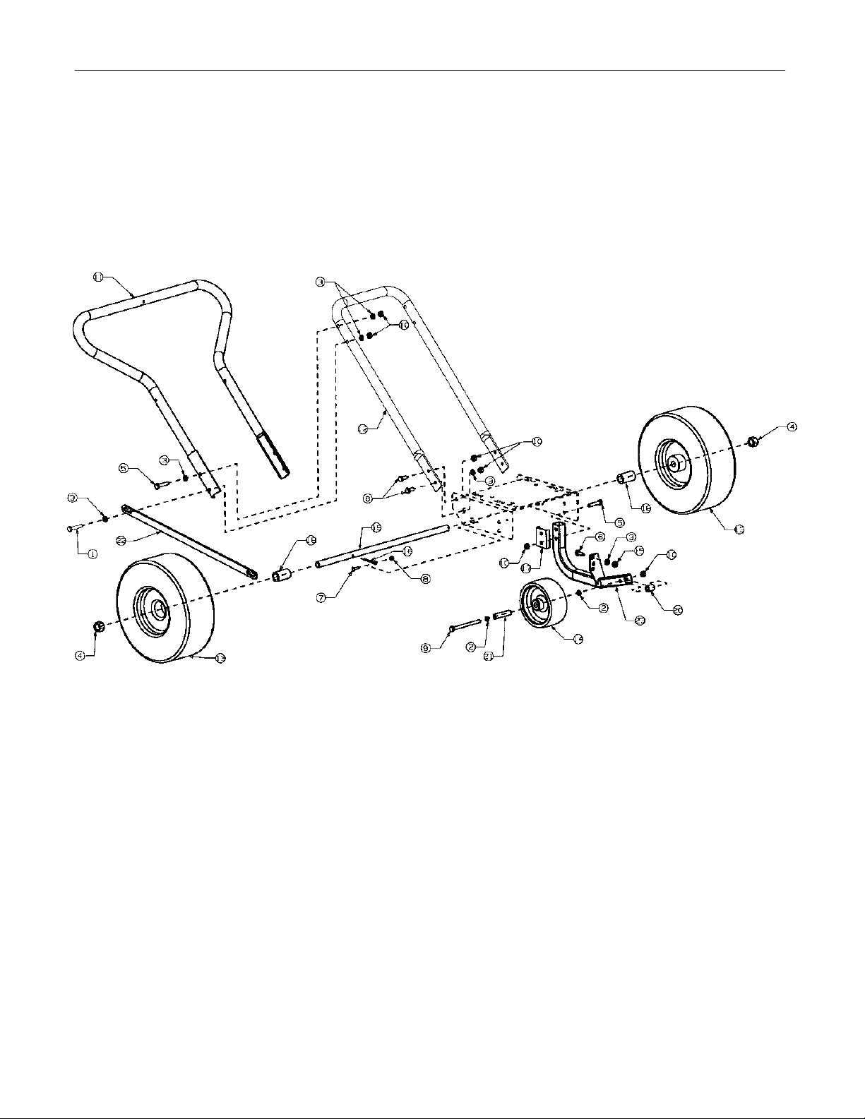
5HP Handle Assembly -
Figure 1
Note:
Use No. 00050539 General Purpose Gun Grease.
4
Page 5

5HP Handle Assembly
Ref.
No. Part No. Description Qty.
1 00006129 HHCS, 5/16-18, 1-3/4 1
2 00011075 Flat Washer, 5/16 USS 2
3 00012169 Flat Washer, SAE 5/16 12
4 00012199 Nut, 5/8-18, Nylock Thin 2
5 00012382 HHCS, Standard, 5/16-18 x 1-1/2 5
6 00013406 HHCS, Standard, 5/16-18 x 3/4 6
7 00030906 Machine Screw, 10-32 x 5/8 1
8 00014608 Nut, Nylon Insert, 10-32 1
9 00022332 HHCS, Standard 5/16-18 x 4 1
10 00022547 Hex Nut Centerlock, 5/16-18 11
11 01001415 Upper Handle 1
12 01001416 Lower Handle 1
13 00031821 Wheel, 11 x 4-4 2
14 00032127 Wheel, 5 x 2 x 1/2 1
15 00034210 Lock Nut, 5/16-18 2
16 00060018 Cotter Pin, 3/16 x 1-1 1
17 01001423 Support Wheel 1
18 01001404 Spacer 2
19 00023094 Axle 1
20 01001405 Spacer Tube Inside 1
21 00030488 Wheel Spacer 1
22 01001414 Brace 1
23 01001418 Frame Assembly 1
- Parts List for Figure 1
Note: Determine which Blower you have purchased from the list below.
Walk-Behind Blower Model No. F5 with 5-H.P. Briggs & Stratton Engine.
Walk-Behind Blower Model No. F8 with 8-H.P. Briggs & Stratton Engine.
5
Page 6

8HP Handle Assembly -
Figure 2
6
Page 7

8HP Handle Assembly
Ref.
No. Part No. Description Qty.
1 00006129 HHCS, 5/16-18, 1-3/4 2
2 00011075 Flat Washer, 5/16 USS 2
3 00012169 Flat Washer, SAE 5/16 12
4 00012199 Nut, 5/8-18, Nylock Thin 2
5 00012382 HHCS, Standard, 5/16-18 x 1-1/2 4
6 00012470 Cable Tie, 3/16 x .05 x 7.4 4
7 00013406 HHCS, Standard, 5/16-18 x 3/4 7
8 00030906 Machine Screw, 10-32 x 5/8 1
9 00014608 Nylon, Lock Nut, 10-32 1
10 00020508 Carriage Bolt, 5/16-18 x 4 1
11 00022332 HHCS, Standard, 5/16-18 x 4 1
12 00022547 Hex Nut, 5/16-18 1
13 00023041 Hex Nut, 1/4-20 Side Lock 1
14 01001415 Upper Handle 1
15 01001416 Lower Handle 1
16 00030472 Control Cable 1
17 00031821 Wheel, 11 x 4 2
18 00032127 Wheel, 5 x 2 x 1/2, Bore 1
19 00034210 Lock Nut, 5/16-18 2
20 00060018 Cotter Pin, 3/16 x 1-1 1
21 00070040 HHCS, Standard, 1/4-20 x 2 1
22 01001423 Support Wheel Frame Plate 1
23 00030489 Throttle Spacer 1
24 01001404 Axle Spacer 2
25 00023094 Axle, Long 1
26 00030492 Spacer, Tube, Inside 1
27 00030488 Spacer Wheel Front 1
28 01001408 Assembly, Frame Wheel 1
29 00030497 Brace, Center Offset 1
30 01001426 Brace, Center Offset 2
- Parts List for Figure 2
7
Page 8

5HP Engine and Blower Assembly -
Figure 3
8
Page 9

5HP Engine and Blower Assembly
Ref.
No. Part No. Description Qty.
1 00006129 HHCS, 5/16-18, 1-3/4 4
2 00010022 Key, Stock, 1/4 x 1 -1/8 1
3 00012134 HHCS, Standard, 1/4-20 x 3/4 1
4 00012168 Lock Washer, 5/16 2
5 00012169 Flat Washer 8
6 00012171 HHCS Standard, 5/16-18 x 3/4 2
7 00012204 Cotter Pin, 3/32 x 3/4 1
8 00013406 HHCS, Standard 5/16-18 x 3/4 2
9 00019919 Capscrew, 5/16-24 x 3/4 2
10 00020508 Carriage Bolt, 5/16-18 x 3/4 1
11 00021682 Screw, Hex, 8-32 x 3/4 2
12 00021683 Nut, Washer w/star 3
13 00022425 Hex Screw, 8-32 x 3/4 1
14 00022547 Nut, Washer w/Star 7
15 00022644 Centerlock Hex Nut, 5/16-18 1
16 00022717 Lock Washer 1
17 00022780 Lock Washer 6
18 00022829 Label, Stop First/Lift 1
19 00023041 Lock Nut, Side 2
20 00023048 Tip, Crutch 1
21 00030268 Label, Danger Fan 2
22 00030468 Label, Safety Procedures 1
23 00030651 Bushing 2
24 00031170 HHCS, Standard, 1/4-20 x 5 1
25 00031193 Spacer, Deflector Assembly 1
26 00022782 Bushing, Nut 1
27 00032673 Lock Washer 1
28 00032678 Hex Head Screw, w/slot 7
29 00034224 Lock Nut, 3/8-16 2
30 00090006 Decal, Made In America 1
31 01001077 Engine Oil, 10W40 by the gallon, not shown .2
32 01001399 Deflector 1
33 01001400 Bracket Assembly 1
34 01001401 Plate Deflector Inside 1
35 01001402 Engine Base 1
36 01001403 Plate Deflector Outside 1
37 01001409 Engine Plate Rise 2
38 00032181 Handle Door Front 1
39 00031395 Latch Front Deflector 1
40 01001412 Assembly Housing 1
41 01001413 Support Center 1
42 01002109 Decal, MTD Pro Tornado 1
43 01001421 Guard Front 1
44 01003705 Compound, Locking Thread, not shown .1
45 00032136 Hub Body 1
46 01004598 Hex Cap Screw, 7/16-20, 3.25 1
47 01000393 Flat Washer, .469 ID, .875 OD, .105 1
- Parts List For Figure 3
9
Page 10

8HP Engine and Blower Assembly -
Figure 3
10
Page 11

8HP Engine and Blower Assembly
Ref.
No. Part No. Description Qty.
1 00006129 HHCS, 5/16-18, 1-3/4 4
2 00010022 Key, Stock, 1/4 x 1 -1/8 1
3 00010980 HHCS, 3/8-16, 2.00 2
4 00012134 HHCS, Standard, 1/4-20 x 3/4 1
5 00012157 Lock Washer, 3/8 2
6 00012169 Flat Washer 7
7 00012204 Cotter Pin, 3/32 x 3/4 1
8 00013406 HHCS, Standard 5/16-18 x 3/4 2
9 00021682 Hex Screw, 8-32 x 3/4 2
10 00021683 Nut, Washer w/Star 3
11 00022547 Centerlock Hex Nut, 5/16-18 6
12 00022780 Lock Washer 6
13 00022784 Fan Casting, 14-1/4 1
14 00022829 Label, Stop First/Lift 1
15 00023041 Lock Nut, Side, 1/4-NC 2
16 00023048 Tip, Crutch 1
17 00025740 Engine, Briggs & Stratton (not shown) 1
18 00030268 Label, Danger Fan 2
19 00030468 Label, Safety Procedures 1
20 00030651 Bushing 2
21 00031170 HHCS, Standard, 1/4-20 x 5 1
22 00031193 Spacer, Deflector Assembly 1
23 00032658 Strap, Lock Housing 1
24 00022782 Bushing, Nut 1
25 00032673 Lock Washer 1
26 00032678 Hex Head Screw, w/slot 7
27 00083192 Washer, Idler 2
28 00090006 Decal, Made in America, not shown 1
29 01001399 Deflector 1
30 01001400 Bracket Assembly 1
31 01001401 Plate Deflector Inside 1
32 01001402 Engine Base 1
33 01001403 Plate Deflector Outside 1
34 00032136 Hub Body 2
35 00032181 Handle Door Front 1
36 00031395 Latch Front Deflector 1
37 01001427 Assembly Housing 1
38 01002110 Decal, MTD Pro Tornado F8 1
39 01001433 Assembly, Guard and Ring 1
40 01003705 Compound, Locking Thread, not shown .1
41 01003720 Spacer, 1.00 ID x 1.25 x 1.50 1
42 01004597 Hex Cap Screw, 3/8-24, 2.50 1
43 00006168 Flat Washer, 3/8 1
- Parts List For Figure 4
11
Page 12

EQUIPMENT ONE-YEAR LIMITED WARRANTY
This warranty is specific for the product manual to which it is attached.
For a complete list of products and warranties contact your dealer.
Proper maintenance of your equipme nt is the ow ner’s res ponsibili ty.
ual for correct lubricants and mainte nance sch edule . Your deal er carrie s a comple te line of quality lu brican ts and fi lters
for your equipment’s engine, transmission, chassis and attachments.
What Is Covered By This Warranty.
1.
Pro equipment for one year from the date of purchase for the first user purchaser. MTD Pro will replace or repair any part
or parts without charge through your authorized MTD Pro dealer. Batteries, belts and tires will be covered for a period of
ninety (90) days from date of purchase. Engine warranties beyond listed coverage, if available, is handled directly with the
engine manufacturer.
What Is Not Covered By This Warranty.
2.
filters (oil, fuel, air and hydraulic), cleaning, tune-ups, brake or clutch inspection, adjustments made as part of normal
maintenance, blade sharpening, setup and normal wear. (b) incidental costs such as transporting equipment to and from
the dealer, telephone charges or renting a product temporarily to replace a warranted product. (c) damage caused by use
of the equipment for purposes other than those for which it was designed; (d) damage caused by accident or disasters
such as fire, flood, wind and lightning; (e) damage caused by unauthorized attachments or modification; or (f) any other
abuse or misuse of the equipment. There is no other express warranty.
Exclusive Warranty.
3.
oral or implied. Any and all implied warranties of merchantability, fitness for a particular purpose, course of dealing or
usage of trade are hereby expressly disclaimed and excluded.
Limitation of Remedies.
4.
liable for any loss or damage, direct or indirect, special, incidental or consequential arising out of the use or inability to use
this equipment including but not limited to any claim for loss of profits, loss of savings or revenue, loss of use of the
equipment or any associated equipment, facilities or service, downtime, the claims or costs of third parties including
customers, and injury to property.
exclusion or limitation of incidental or consequential damages, so the above limitations or exclusion may not apply to you.
This warranty gives you specific legal rights, and you may also have other rights which vary from state to state.
Future Changes:
5.
or any component part or parts thereof without incurring the obligations to make such changes or modifications in present
equipment.
How to Obtain Service:
6.
replacement parts. If you need further assistance in finding an authorized servicing dealer, contact:
The foregoing warranty is exclusive and in lieu of all other warranties or remedies, whether written,
Under no circumstances, except to the extent prohibited by applicable law, shall MTD Pro be
MTD Pro reserves the right to r eserve, ch ange or modi fy the const ruction and desig n of its Equi pment
Contact the authorized MTD Pro dealer who sold you your equipment to obtain service or
This limi ted warra nty covers any defec t in mat erials or w orkmanshi p in your MTD
MTD Pro does not warrant (a) routine maintenance items such as lubricants,
Some states do not allow limitations on how long an implied warranty lasts or the
Follow the instructi ons in y our ow ner’s man-
Form No. 01003864 Rev 99-3
MTD Pro
P.O. Box 361131
Cleveland, Ohio 44136
 Loading...