

Page 1

Safe Operation Practices • Set-Up • Operation • Maintenance • Service • Troubleshooting • Warranty
L
Self Propelled Mower m Model E18J
MTD LLC, P.O. BOX 361131 CLEVELAND, OHiO 44136-0019
PrintedIn USA FormNo.769-05753
(December15,2009)
Page 2
ToTheOwner
ThankYou
Thank you for purchasing a Lawn Mower manufactured by MTD.
It was carefully engineered to provide excellent performance
when properly operated and maintained.
Please read this entire manual prior to operating the equipment.
It instructs you how to safely and easily set up, operate and
maintain your machine. Please be sure that you, and any other
persons who will operate the machine, carefully follow the
recommended safety practices at all times. Failure to do so could
result in personal injury or property damage.
All information in this manual is relative to the most recent
product information available at the time of printing. Review
this manual frequently to familiarize yourself with the machine,
its features and operation. Please be aware that this Operator's
Tableof Contents
1
Manual may cover a range of product specifications for various
models. Characteristics and features discussed and/or illustrated
in this manual may not be applicable to all models. We reserve
the right to change product specifications, designs and
equipment without notice and without incurring obligation.
If you have any problems or questions concerning the machine,
phone your local authorized MTD service dealer or contact us
directly. MTD's Customer Support telephone numbers, website
address and mailing address can be found on this page. We want
to ensure your complete satisfaction at all times.
Throughout this manual, all references to right and left side of the
machine are observed from the operating position.
Safe Operation Practices ........................................ 3
Assembly & Set-Up .................................................. 9
Controls & Features ................................................ 12
Operation ................................................................ 13
Maintenance &Adjustment. ................................. 14
Service ..................................................................... 16
RecordProductinformation
Before setting up and operating your new equipment, please
locate the model plate on the equipment and record the
information in the provided area to the right. You can locate the
model plate by standing at the operator's position and looking
down at the rear of the deck. This information will be necessary,
should you seek technical support via our web site, Customer
Support Department, or with a local authorized service dealer.
Troubleshooting ..................................................... 19
Engine Operation ................................................... 21
Engine Maintenance ............................................. 23
Replacement Parts ................................................ 28
Warranty ................................................................ 32
Spanish ................................................................... 33
MODEL NUMBER
[3131313131313131313D
SERIAL NUMBER
DflDflDflDflDflD
CustomerSupport
Please do NOT return the machine to the retailer or dealer without first contacting our Customer Support Department.
If you have difficulty assembling this product or have any questions regarding the controls, operation, or maintenance of
this machine, you can seek help from the experts. Choose from the options below:
0 Visit us on the web at www.mtdproducts.com
0 Call a Customer Support Representative at (800) 800-7310 or (330) 220-4683
0 Write us at MTD LLC • EO. Box 361131 • Cleveland, OH • 44136-0019
Page 3
importantSafeOperationPractices
WARNING: This symbol points out important safety instructions which, if not followed,
could endanger the personal safety and/or property of yourself and others. Read and follow
all instructions in this manual before attempting to operate this machine. Failure to comply
with these instructions may result in personal injury.
When you see this symbol. HEED ITS WARNING!
CALIFORNIA PROPOSITION 65
WARNING: Engine Exhaust, some of its constituents, and certain vehicle components
contain or emit chemicals known to State of California to cause cancer and birth defects
or other reproductive harm.
WARNING: Battery posts, terminals, and related accessories contain lead and lead
,A
compounds, chemicals known to the State of California to cause cancer and reproductive
harm. Wash hands after handling.
DANGER: This machine was built to be operated according to the safe operation practices in
this manual. As with any type of power equipment, carelessness or error on the part of the
operator can result in serious injury. This machine is capable of amputating fingers, hands,
toes and feet and throwing objects. Failure to observe the following safety instructions could
result in serious injury or death.
2
GeneralOperation
1. Read this operator's manual carefully in its entirety before
attempting to assemble this machine. Read, understand,
and follow all instructions on the machine and in the
manual(s) before operation. Keep this manual in a safe
place for future and regular reference and for ordering
replacement parts.
2. Be completely familiar with the controls and the proper use
of this machine before operating it.
3. This machine is a precision piece of power equipment,
not a plaything. Therefore, exercise extreme caution at all
times. This machine has been designed to perform one job:
to mow grass. Do not use it for any other purpose.
4. Never allow children under 14 years of age to operate this
machine. Children 14 and over should read and understand
the instructions and safe operation practices in this manual
and on the machine and should be trained and supervised
by an adult.
5. Only responsible individuals who are familiar with these
rules of safe operation should be allowed to use this
machine.
6. Thoroughly inspect the area where the equipment is to be
used. Remove all stones, sticks, wire, bones, toys and other
foreign objects, which could be tripped over or picked up
and thrown by the blade. Thrown objects can cause serious
personal injury.
7. Plan your mowing pattern to avoid discharge of material
toward roads, sidewalks, bystanders and the like. Also,
avoid discharging material against a wall or obstruction,
which may cause discharged material to ricochet back
toward the operator.
8. To help avoid blade contact or a thrown object injury,
stay in operator zone behind handles and keep children,
bystanders, helpers and pets at least 75 feet from mower
while it is in operation. Stop machine if anyone enters area.
9. Always wear safety glasses or safety goggles during
operation and while performing an adjustment or repair
to protect your eyes. Thrown objects which ricochet can
cause serious injury to the eyes.
10. Wear sturdy, rough-soled work shoes and close-fitting
slacks and shirts. Shirts and pants that cover the arms
and legs and steel-toed shoes are recommended. Never
operate this machine in bare feet, sandals, slippery or light-
weight (e.g. canvas) shoes.
11. Do not put hands or feet near rotating parts or under the
cutting deck. Contact with blade can amputate fingers,
hands, toes and feet.
Page 4
12. Amissingordamageddischargecovercancauseblade 27.
contactorthrownobjectinjuries.
13. Manyinjuriesoccurasaresultofthemowerbeingpulled
overthefootduringafallcausedbyslippingortripping.
Donotholdontothemowerifyouarefalling;releasethe
handleimmediately. 28.
14. Neverpullthemowerbacktowardyouwhileyouare
walking.Ifyoumustbackthemowerawayfromawallor
obstructionfirstlookdownandbehindtoavoidtripping
andthenfollowthesesteps:
a. Stepbackfrommowertofullyextendyourarms.
b. Besureyouarewellbalancedwithsurefooting.
c. Pullthemowerbackslowly,nomorethanhalfway
towardyou.
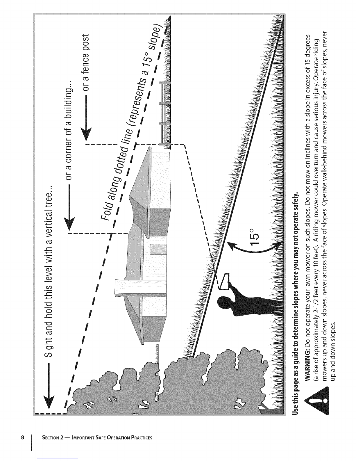
Slope Operation
Slopes are a major factor related to slip and fall accidents, which
can result in severe injury. Operation on slopes requires extra
caution. If you feel uneasy on a slope, do not mow it. For your
safety, use the slope gauge included as part of this manual to
measure slopes before operating this machine on a sloped or
hilly area. If the slope is greater than 15 degrees, do not mow it.
d. Repeatthesestepsasneeded.
15. Do not operate the mower while under the influence of
alcohol or drugs. 1.
16. Do not engage the self-propelled mechanism on machines
so equipped while starting engine. 2.
17. The blade control is a safety device. Never attempt to
bypass its operation. Doing so makes the safety device
inoperative and may result in personal injury through 3.
contact with the rotating blade. The blade control must
operate easily in both directions and automatically return
to the disengaged position when released.
18. Never operate the mower in wet grass. Always be sure of Do Not:
your footing. A slip and fall can cause serious personal
injury. If you feel you are losing your footing, release the
blade control handle immediately and the blade will stop
rotating within three seconds.
19.
Mow only in daylight or good artificial light. Walk, never
run.
20.
Stop the blade when crossing gravel drives, walks or roads.
21.
If the equipment should start to vibrate abnormally, stop
the engine and check immediately for the cause. Vibration
is generally a warning of trouble.
22.
Shut the engine off and wait until the blade comes to
acomplete stop before removing the grasscatcher or
unclogging the chute. The cutting blade continues to
rotate for afew seconds after the blade control is released.
Never place any part of the body in the blade area until you
are sure the blade hasstopped rotating.
23.
Never operate mower without proper trail shield,
discharge cover, grasscatcher, blade control or other safety
protective devices in place and working. Never operate
mower with damaged safety devices. Failure to do socan
result in personal injury.
24.
Muffler and engine become hot and can causea burn. Do
not touch.
25.
Never attempt to make a wheel or cutting height
adjustment while the engine is running.
26.
Only use parts and accessories made for this machine by
the manufacturer. Failure to do so can result in personal
injury.
Do:
1. Do not mow near drop-offs, ditches or embankments, you
2. Do not mow slopes greater than 15degrees as shown on
3. Do not mow on wet grass.Unstable footing could cause
Children
Tragic accidents can occur if the operator is not alert to the
presence of children. Children are often attracted to the mower
and the mowing activity. They do not understand the dangers.
Never assume that children will remain where you last saw them.
1.
2.
3.
4.
5.
6.
When starting engine, pull cord slowly until resistance
is felt, then pull rapidly. Rapid retraction of starter cord
(kickback) will pull hand and arm toward engine faster than
you can let go. Broken bones, fractures, bruises or sprains
could result.
If situations occur which are not covered in this manual,
use care and good judgement. Contact Customer Support
for assistance or the name of the nearest service dealer.
Mow across the face of slopes; never up and down. Exercise
extreme caution when changing direction on slopes.
Watch for holes, ruts, rocks, hidden objects, or bumps
which can cause you to slip or trip. Tall grass can hide
obstacles.
Always be sure of your footing. A slip and fall can cause
serious personal injury. If you feel you are losing your
balance, release the blade control handle immediately and
the blade will stop rotating within three (3) seconds.
could lose your footing or balance.
the slope gauge.
slipping.
Keep children out of the mowing area and under watchful
care of a responsible adult other than the operator.
Be alert and turn mower off if a child enters the area.
Before and while moving backwards, look behind and
down for small children.
Use extreme care when approaching blind corners,
doorways, shrubs, trees, or other objects that may obscure
your vision of a child who may run into the mower.
Keep children away from hot or running engines. They can
suffer burns from a hot muffler.
Never allow children under 14 years of age to operate this
machine. Children 14 and over should read and understand
the instructions and safe operation practices in this manual
and on the machine and be trained and supervised by an
adult.
4 I SECTION 2 -- IMPORTANT SAFE OPERATION PRACTICES
Page 5
Service
SafeHandling OfGas01ine:
I. To avoid personal injury or property damage use extreme
care in handling gasoline. Gasoline is extremely flammable
and the vapors are explosive. Serious personal injury can
occur when gasoline is spilled on yourself or your clothes,
which can ignite. Wash your skin and change clothes
immediately.
2. Use only an approved gasoline container.
3. Never fill containers inside a vehicle or on a truck or trailer
bed with a plastic liner. Always place containers on the
ground away from your vehicle before filling.
4. Remove gas-powered equipment from the truck or
trailer and refuel it on the ground. If this is not possible,
then refuel such equipment on a trailer with a portable
container, rather than from a gasoline dispenser nozzle.
5. Keep the nozzle in contact with the rim of the fuel tank or
container opening at all times until fueling is complete. Do
not use a nozzle lock-open device.
6.
Extinguish all cigarettes, cigars, pipes and other sources
of ignition.
7.
Never fuel machine indoors because flammable vapors will
accumulate in the area.
8.
Never remove gas cap or add fuel while engine is hot or
running. Allow engine to cool at least two minutes before
refueling.
9. Never overfill fuel tank. Filltankto no more than I inch
below bottom of filler neck to provide for fuel expansion.
I0. Replace gasoline cap and tighten securely.
1I. If gasoline is spilled, wipe it off the engine and equipment.
Move machine to another area. Wait 5 minutes before
starting engine.
12. Never store the machine or fuel container near an open
flame, spark or pilot light as on a water heater, space
heater, furnace, clothes dryer or other gas appliances.
13. To reduce fire hazard, keep machine free of grass, leaves,
or other debris build-up. Clean up oil or fuel spillage and
remove any fuel soaked debris.
14. Allow machine to cool at least 5 minutes before storing.
GeneralService:
I. Never run an engine indoors or in a poorly ventilated area.
Engine exhaust contains carbon monoxide, an odorless
and deadly gas.
2. Before cleaning, repairing, or inspecting, make certain the
blade and all moving parts have stopped. Disconnect the
spark plug wire and ground against the engine to prevent
unintended starting.
3. Check the blade and engine mounting bolts at frequent
intervals for proper tightness. Also, visually inspect blade
for damage (e.g., bent, cracked, worn) Replace blade with
the original equipment manufacture's (O.E.M.) blade only,
listed in this manual. "Use of parts which do not meet the
original equipment specifications may lead to improper
performance and compromise safety!"
4. Mower blades are sharp and can cut. Wrap the blade or
wear gloves, and use extra caution when servicing them.
5. Keep all nuts, bolts, and screws tight to be sure the
equipment is in safe working condition.
6. Never tamper with safety devices. Check their proper
operation regularly.
7. After striking a foreign object, stop the engine, disconnect
the spark plug wire and ground against the engine.
Thoroughly inspect the mower for any damage. Repair the
damage before starting and operating the mower.
8. Never attempt to make a wheel or cutting height
adjustment while the engine is running.
9. Grass catcher components, discharge cover, and trail shield
are subject to wear and damage which could expose
moving parts or allow objects to be thrown. For safety
protection, frequently check components and replace
immediately with original equipment manufacturer's
(O.E.M.) parts only, listed in this manual. "Use of parts
which do not meet the original equipment specifications
may lead to improper performance and compromise
safety!"
10. Do not change the engine's governor setting or over-speed
the engine. The governor controls the maximum safe
operating speed of the engine.
11. Check fuel line, tank, cap, and fittings frequently for cracks
or leaks. Replace if necessary.
12. Do not crank engine with spark plug removed.
13. Maintain or replace safety and instruction labels, as
necessary.
14. Observe proper disposal laws and regulations. Improper
disposal of fluids and materials can harm the environment.
15. According to the Consumer Products Safety Commission
(CPSC) and the U.S. Environmental Protection Agency (EPA),
this product has an Average Useful Life of seven (7) years,
or 140 hours of operation. At the end of the Average Useful
Life have the machine inspected annually by an authorized
service dealer to ensure that all mechanical and safety
systems are working properly and not worn excessively.
Failure to do so can result in accidents, injuries or death.
Donot modify engine
To avoid serious injury or death, do not modify engine in any
way. Tampering with the governor setting can lead to a runaway
engine and cause it to operate at unsafe speeds. Never tamper
with factory setting of engine governor.
SECTION 2 -- IMPORTANT SAFE OPERATION PRACTICES S
Page 6
Notice Regarding Emissions
Engines which are certified to comply with California and federal
EPA emission regulations for SORE (Small Off Road Equipment)
are certified to operate on regular unleaded gasoline, and
may include the following emission control systems: Engine
Modification (EM), Oxidizing Catalyst (OC), Secondary Air
Injection (SAI) and Three Way Catalyst (TWC) if so equipped.
SparkArrestor
i_ll WARNING: This machine is equipped with an
Ira spark arrester is used, it should be maintained in effective
working order by the operator. In the State of California the
above is required by law (Section 4442 of the California Public
Resources Code). Other states may have similar laws. Federal laws
apply on federal lands.
A spark attester for the muffler is available through your
nearest engine authorized service dealer or contact the service
department, RO. Box 361131 Cleveland, Ohio 44136-0019.
internal combustion engine and should not be used
on or near any unimproved forest-covered, brush
covered or grass-covered land unless the engine's
exhaust system is equipped with a spark arrester
meeting applicable local or state laws (if any).
6 I SECTION 2 -- IMPORTANT SAFE OPERATION PRACTICES
Page 7
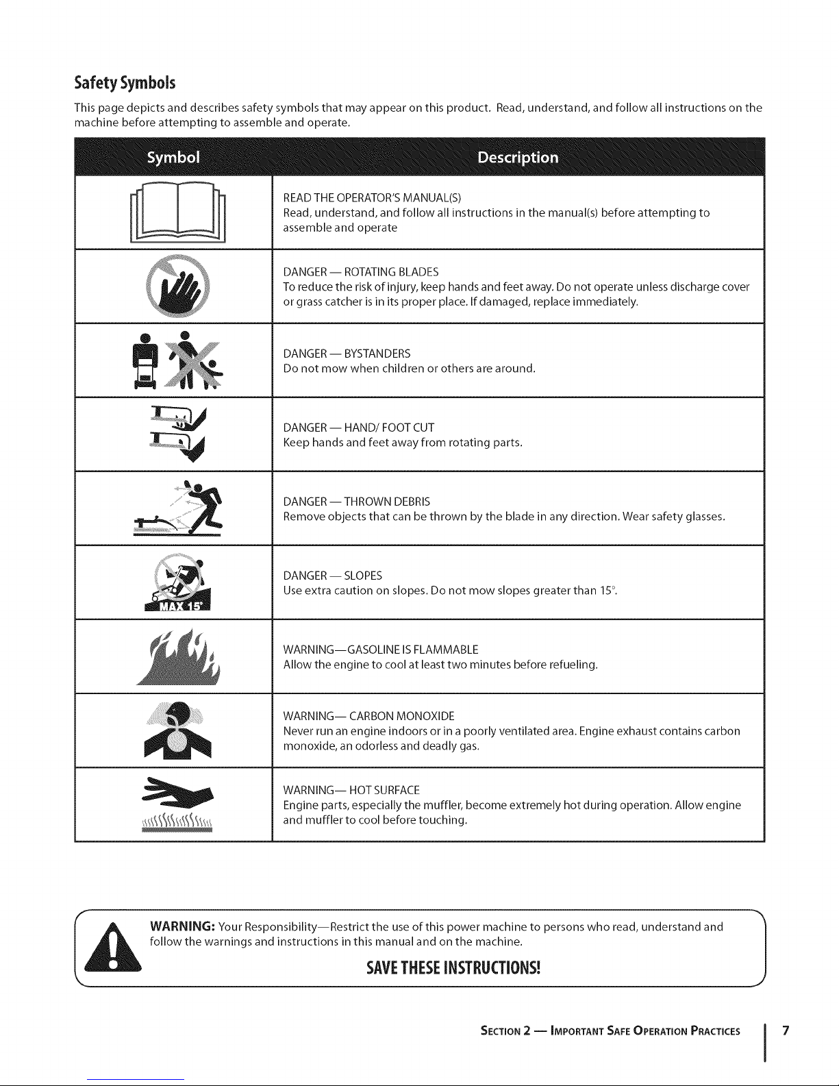
Safety Symbols
This page depicts and describes safety symbols that may appear on this product. Read, understand, and follow all instructions on the
machine before attempting to assemble and operate.
READ THE OPERATOR'S MANUAL(S)
Read, understand, and follow all instructions in the manual(s) before attempting to
assemble and operate
DANGER -- ROTATING BLADES
To reduce the risk of injury, keep hands and feet away. Do not operate unless discharge cover
or grass catcher is in its proper place. If damaged, replace immediately.
®
i|1_
Do not mow when children or others are around.
IRFS
_1_ DANGER-- HAND/FOOT CUT
Keep hands and feet away from rotating parts.
DANGER -- THROWN DEBRIS
Remove objects that can be thrown by the blade in any direction. Wear safety glasses.
DANGER -- SLOPES
Use extra caution on slopes. Do not mow slopes greater than 15°.
,_ _ WARNING--GASOLINEIS FLAMMABLE
__\_%._ and muffler to cool before touching.
Allow the engine to cool at least two minutes before refueling.
WARNING-- CARBON MONOXIDE
Never run an engine indoors or in a poorly ventilated area. Engine exhaust contains carbon
monoxide, an odorless and deadly gas.
WARNING-- HOT SURFACE
Engine parts, especially the muffler, become extremely hot during operation. Allow engine
follow the warnings and instructions in this manual and on the machine.
Ii_ WARNING: Your Responsibility--Restrict the use of this power machine to persons who read, understand and |
SAVETHESEINSTRUCTIONS!
SECTION 2 -- IMPORTANT SAFE OPERATION PRACTICES 7
J
Page 8
C
o _
oo
0
_D
0
C
c_
0
co
co
o I
qo
c_
0
oO
0
C
0
0
0
=
mm I
I
I
I
I
I
I
I
I
l
l
l
l
l
l
l
l
l
0
I
I
I
I
I
I
/
/
oO
I
I
I
SECTION 2 -- IMPORTANT SAFE OPERATION PRACTICES
Page 9
Assembly& Set-Up
Contents of Carton
3
One Lawn Mower
One Lawn Mower Operator's Manual
One Grass Catcher
One Side Discharge Chute
Assembly
NOTE:This unit is shipped without gasoline or oil in the engine.
Fill up gasoline and oil asinstructed in the Engine Operation
section of this manual BEFOREoperating your mower.
Handle
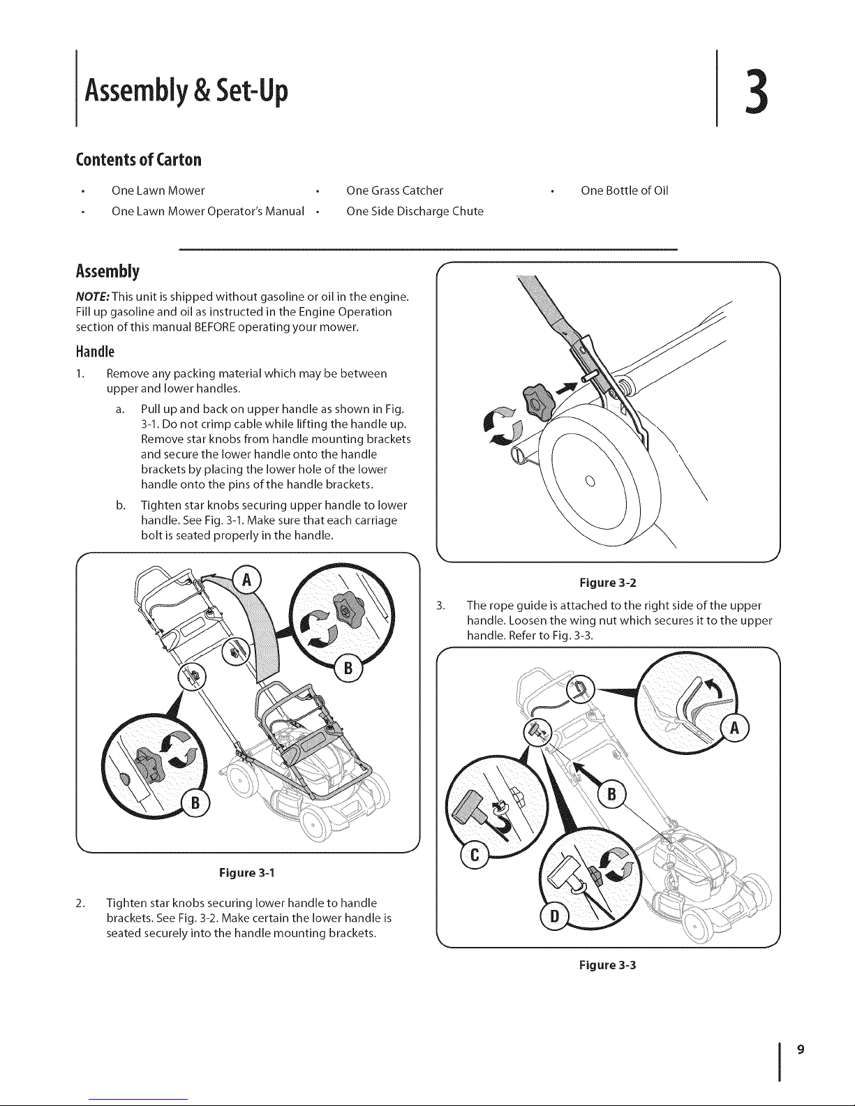
1.
Remove any packing material which may be between
upper and lower handles.
a. Pull up and back on upper handle as shown in Fig.
3-1. Do not crimp cable while lifting the handle up.
Remove star knobs from handle mounting brackets
and secure the lower handle onto the handle
brackets by placing the lower hole of the lower
handle onto the pins of the handle brackets.
b. Tighten star knobs securing upper handle to lower
handle. See Fig. 3-1. Make sure that each carriage
bolt is seated properly in the handle.
One Bottle of Oil
Figure 3-2
3.
The rope guide is attached to the right side of the upper
handle. Loosen the wing nut which secures it to the upper
handle. Refer to Fig. 3-3.
J
Figure 3-1
2. Tighten star knobs securing lower handle to handle
brackets. See Fig. 3-2. Make certain the lower handle is
seated securely into the handle mounting brackets.
Figure 3-3
Page 10
a. Hold blade control against upper handle.
b. Pull starter rope out of the engine. Release blade
control handle.
c. Slip starter rope into rope guide.
d. Tighten wing nut.
4.
Insert post on cable ties into holes provided on the lower
handle. Pull cable tie tight and trim excess.
GrassCatcher
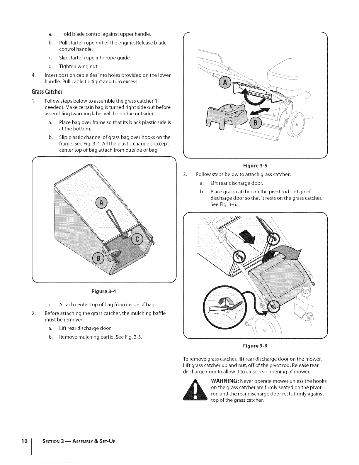
1.
Follow steps below to assemble the grass catcher (if
needed). Make certain bag is turned right side out before
assembling (warning label will be on the outside).
a. Place bag over fra me so that its black plastic side is
at the bottom.
b.
Slip plastic channel of grass bag over hooks on the
frame. See Fig. 3-4. All the plastic channels except
center top of bag attach from outside of bag.
f
Figure 3=5
3. Follow steps below to attach grass catcher:
a. Lift rear discharge door.
b. Place grass catcher on the pivot rod. Let go of
discharge door so that it rests on the grass catcher.
See Fig. 3-6.
Figure 3-4
c. Attach center top of bag from inside of bag.
2.
Before attaching the grass catcher, the mulching baffle
must be removed.
a. Lift rear discharge door.
b. Remove mulching baffle. See Fig. 3-5.
SECTION 3 -- ASSEMBLY& SET-UP
'°1
J
Figure 3-6
To remove grass catcher, lift rear discharge door on the mower.
Lift grass catcher up and out, off of the pivot rod. Release rear
discharge door to allow it to close rear opening of mower.
WARNING: Never operate mower unless the hooks
on the grass catcher are firmly seated on the pivot
rod and the rear discharge door rests firmly against
top of the grass catcher.
Page 11
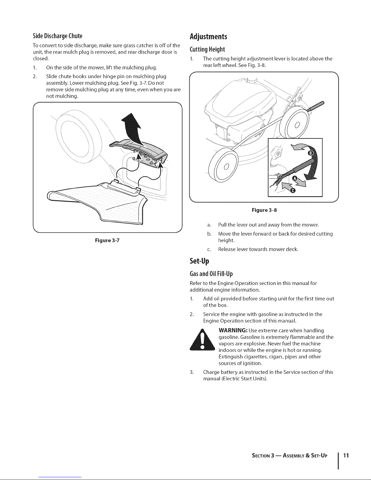
SideDischargeChute
To convert to side discharge, make sure grass catcher is off of the
unit, the rear mulch plug is removed, and rear discharge door is
closed.
On the side of the mower lift the mulching plug.
2.
Slide chute hooks under hinge pin on mulching plug
assembly. Lower mulching plug. See Fig. 3-7. Do not
remove side mulching plug at any time, even when you are
not mulching.
Adjustments
CuttingHeight
1. The cutting height adjustment lever is located above the
rear left wheel. See Fig. 3-8.
f
// //
Figure 3-8
Figure 3-7
a. Pull the lever out and away from the mower.
b. Move the lever forward or back for desired cutting
height.
c. Release lever towards mower deck.
Set-Lip
(;asand OilFill-Up
Refer to the Engine Operation section in this manual for
additional engine information.
1. Add oil provided before starting unit for the first time out
of the box.
2. Service the engine with gasoline as instructed in the
Engine Operation section of this manual.
WARNING: Use extreme care when handling
gasoline. Gasoline is extremely flammable and the
vapors are explosive. Never fuel the machine
indoors or while the engine is hot or running.
Extinguish cigarettes, cigars, pipes and other
sources of ignition.
3. Charge battery as instructed in the Service section of this
manual (Electric Start Units).
SECTION3 -- ASSEMBLY& SET-UP 11
Page 12
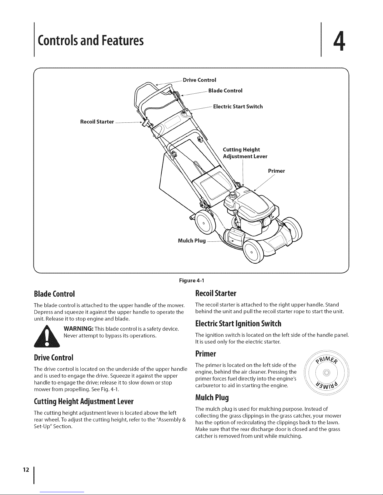
ControlsandFeatures
Recoil Starter ...............
4
Switch
Cutting Height
\ \\ Adjustment Lever
Mulch Plug
Figure 4-1
BladeControl
The blade control is attached to the upper handle of the mower.
Depress and squeeze it against the upper handle to operate the
unit. Release it to stop engine and blade.
_ ARNING: This blade control is a safety device.
Never attempt to bypass its operations.
DriveControl
The drive control is located on the underside of the upper handle
and is used to engage the drive. Squeeze it against the upper
handle to engage the drive; release it to slow down or stop
mower from propelling. See Fig.4-1.
Cutting HeightAdjustmentLever
The cutting height adjustment lever is located above the left
rear wheel. To adjust the cutting height, refer to the "Assembly &
Set-Up" Section.
J
gecoUStarter
The recoil starter is attached to the right upper handle. Stand
behind the unit and pull the recoil starter rope to start the unit.
ElectricStartIgnition Switch
The ignition switch is located on the left side of the handle panel.
It is used only for the electric starter.
Primer
The primer is located on the left side of the
engine, behind the air cleaner.Pressing the
primer forces fuel directly into the engine's
carburetor to aid in starting the engine.
MulchPlug
The mulch plug is used for mulching purpose. Instead of
collecting the grassclippingsin the grasscatcher,your mower
has the option of recirculating the clippingsback to the lawn.
Make sure that the rear discharge door is closedand the grass
catcheris removed from unit while mulching.
Page 13
Operation
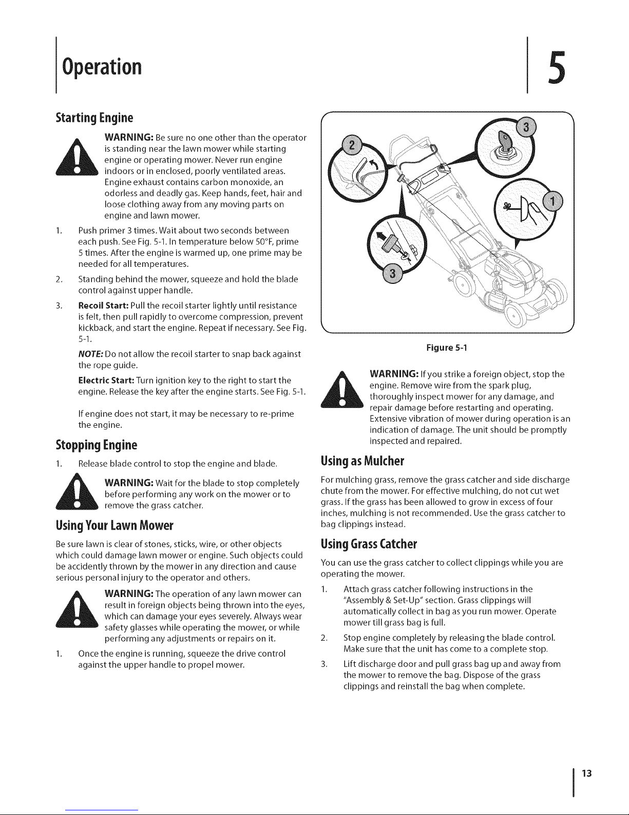
Starting Engine
WARNING: Be sure no one other than the operator
isstanding near the lawn mower while starting
engine or operating mower. Never run engine
indoors or in enclosed, poorly ventilated areas.
Engine exhaust contains carbon monoxide, an
odorless and deadly gas. Keep hands, feet, hair and
loose clothing away from any moving parts on
engine and lawn mower.
Push primer 3times. Wait about two seconds between
each push. See Fig. 5-1. Intemperature below 50°F, prime
5times. After the engine iswarmed up, one prime may be
needed for all temperatures.
2_
Standing behind the mower, squeeze and hold the blade
control against upper handle.
3.
Recoil Start: Pull the recoil starter lightly until resistance
isfelt, then pull rapidly to overcome compression, prevent
kickback, and start the engine. Repeat if necessary. See Fig.
5-1.
NOTE: Do not allow the recoil starter to snap back against
the rope guide.
Electric Start: Turn ignition key to the right to start the
engine. Release the key after the engine starts. See Fig. 5-1.
If engine does not start, it may be necessary to re-prime
the engine.
Stopping Engine
1. Releaseblade control to stop the engine and blade.
i_ WARNING: Wait for the blade to stop completely
UsingYourlawn Mower
Be sure lawn is clear of stones, sticks, wire, or other objects
which could damage lawn mower or engine. Such objects could
be accidently thrown by the mower in any direction and cause
serious personal injury to the operator and others.
i_ WARNING: The operation of any lawn mower can
1. Once the engine is running, squeeze the drive control
before performing any work on the mower or to
remove the grasscatcher.
result in foreign objects being thrown into the eyes,
which can damage your eyes severely. Always wear
safety glasses while operating the mower, or while
performing any adjustments or repairs on it.
against the upper handle to propel mower.
Figure 5-1
WARNING: If you strike a foreign object, stop the
engine. Remove wire from the spark plug,
thoroughly inspect mower for any damage, and
repair damage before restarting and operating.
Extensive vibration of mower during operation isan
indication of damage. The unit should be promptly
inspected and repaired.
UsingasMulcher
For mulching grass, remove the grass catcher and side discharge
chute from the mower. For effective mulching, do not cut wet
grass. If the grass has been allowed to grow in excess of four
inches, mulching is not recommended. Use the grass catcher to
bag clippings instead.
UsingGrassCatcher
You can use the grass catcher to collect clippings while you are
operating the mower.
1. Attach grass catcher following instructions in the
"Assembly & Set-Up" section. Grass clippings will
automatically collect in bag as you run mower. Operate
mower till grass bag is full.
2. Stop engine completely by releasing the blade control.
Make sure that the unit has come to a complete stop.
3. Lift discharge door and pull grass bag up and away from
the mower to remove the bag. Dispose of the grass
clippings and reinstall the bag when complete.
13
Page 14
Maintenance&Adjustments
Maintenance
GeneralRecommendations
Always observe safety rules when performing any
maintenance.
The warranty on this lawn mower does not cover items that
have been subjected to operator abuse or negligence. To
receive full value from warranty, operator must maintain
the lawn mower as instructed here.
Changing of engine-governed speed will void engine
wa rra nty.
All adjustments should be checked at least once each
season.
Periodically check all fasteners and make sure these are
tight.
i,_l_l_liL WARNING: Always stop engine, disconnect spark
Lubrication
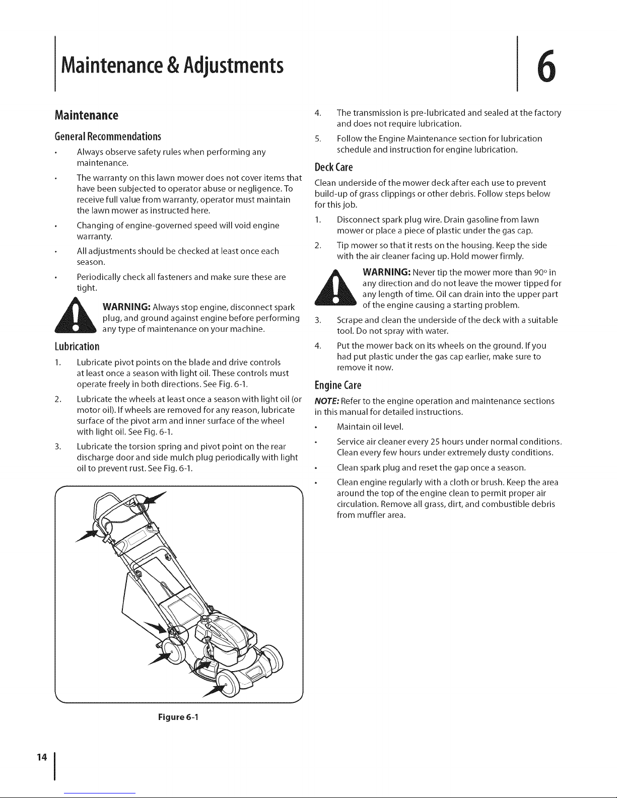
1. Lubricate pivot points on the blade and drive controls
2. Lubricate the wheels at least once a season with light oil (or
3. Lubricate the torsion spring and pivot point on the rear
plug, and ground against engine before performing
any type of maintenance on your machine.
at least once a season with light oil. These controls must
operate freely in both directions. See Fig. 6-1.
motor oil). If wheels are removed for any reason, lubricate
surface of the pivot arm and inner surface of the wheel
with light oil. See Fig. 6-1.
discharge door and side mulch plug periodically with light
oil to prevent rust. See Fig. 6-1.
4. The transmission is pre-lubricated and sealed at the factory
and does not require lubrication.
5. Follow the Engine Maintenance section for lubrication
schedule and instruction for engine lubrication.
DeckCare
Clean underside of the mower deck after each use to prevent
build-up of grass clippings or other debris. Follow steps below
for this job.
1. Disconnect spark plug wire. Drain gasoline from lawn
mower or place a piece of plastic under the gas cap.
2. Tip mower so that it rests on the housing. Keep the side
with the air cleaner facing up. Hold mower firmly.
any direction and do not leave the mower tipped for
_I_ WARNING: Never tip the mower more than 90° in
3. Scrape and clean the underside of the deck with a suitable
4. Put the mower back on its wheels on the ground. Ifyou
any length of time. Oil can drain into the upper part
of the engine causing a starting problem.
tool. Do not spray with water.
had put plastic under the gas cap earlier, make sure to
remove it now.
EngineCare
NOTE: Refer to the engine operation and maintenance sections
in this manual for detailed instructions.
Maintain oil level.
Service air cleaner every 25 hours under normal conditions.
Clean every few hours under extremely dusty conditions.
Clean spark plug and reset the gap once a season.
Clean engine regularly with a cloth or brush. Keep the area
around the top of the engine clean to permit proper air
circulation. Remove all grass, dirt, and combustible debris
from muffler area.
Figure 6-1
Page 15
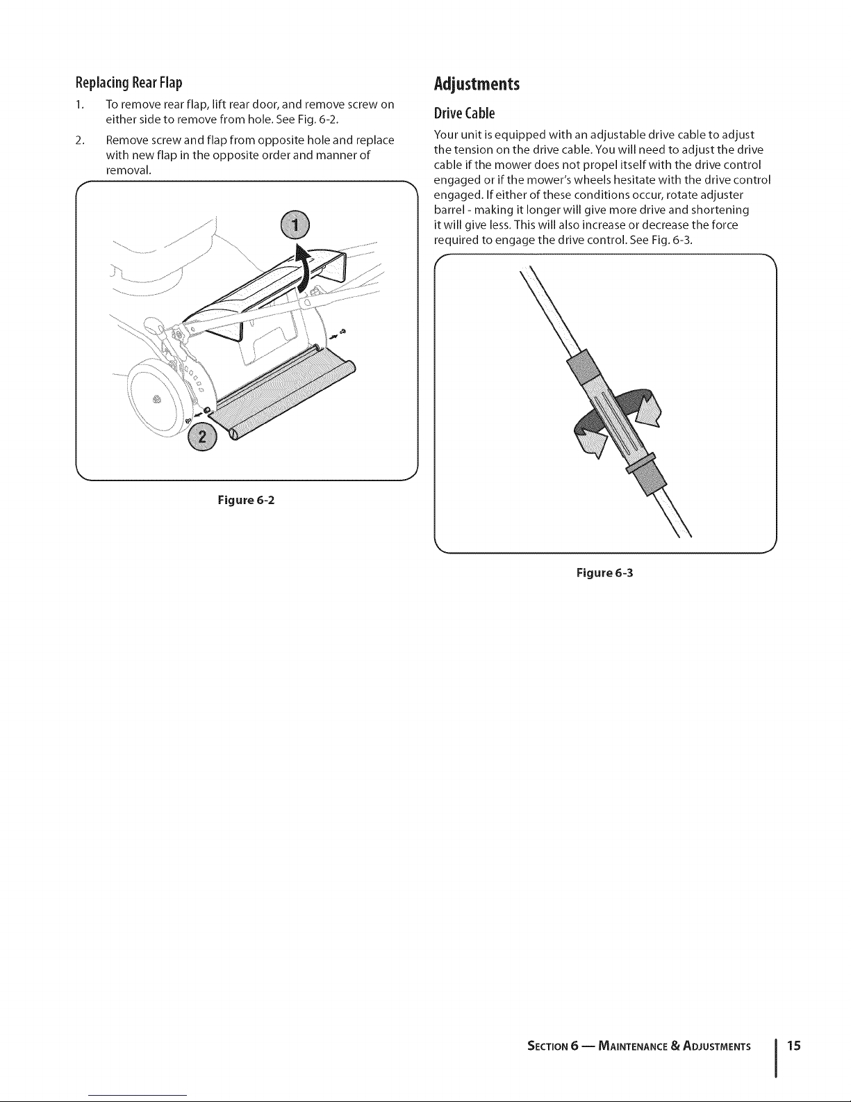
ReplacingRearHap
1. To remove rear flap, lift rear door, and remove screw on
either side to remove from hole. See Fig. 6-2.
2. Remove screw and flap from opposite hole and replace
with new flap in the opposite order and manner of
removal.
s _¸¸i
Adjustments
Drive(:able
Your unit is equipped with an adjustable drive cable to adjust
the tension on the drive cable. You will need to adjust the drive
cable if the mower does not propel itself with the drive control
engaged or if the mower's wheels hesitate with the drive control
engaged. If either of these conditions occur, rotate adjuster
barrel - making it longer will give more drive and shortening
it will give less. This will also increase or decrease the force
required to engage the drive control. See Fig. 6-3.
Figure 6=2
Figure 6=3
SECTION 6 -- MAINTENANCE & ADJUSTMENTS 15
Page 16
Service
7
BladeCare
WARNING: When removing the cutting blade for
sharpening or replacement, protect your hands with
a pair of heavy gloves or use a heavy rag to hold the
blade.
Periodically inspect the blade adapter for cracks, especially if you
strike a foreign object. Replace when necessary. Follow the steps
below for blade service.
1.
Disconnect spark plug boot from spark plug. Turn mower
on its side making sure that the air filter and the carburetor
are facing up.
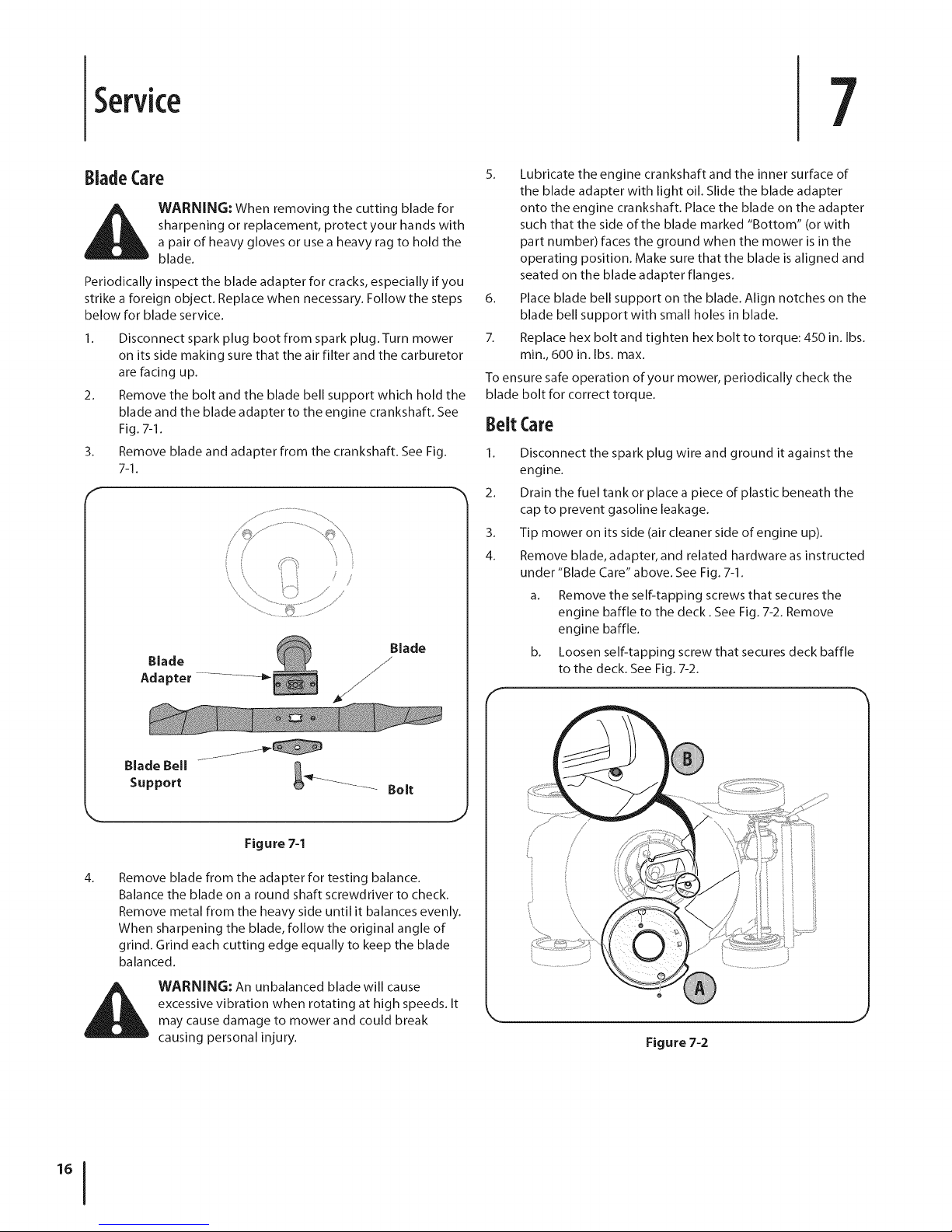
2.
Remove the bolt and the blade bell support which hold the
blade and the blade adapter to the engine crankshaft. See
Fig. 7-1.
3.
Remove blade and adapter from the crankshaft. See Fig.
7-1.
Blade
Blade
J
Adapter ....................
Y
5. Lubricate the engine crankshaft and the inner surface of
the blade adapter with light oil. Slide the blade adapter
onto the engine crankshaft. Place the blade on the adapter
such that the side of the blade marked "Bottom" (or with
part number) faces the ground when the mower is in the
operating position. Make sure that the blade is aligned and
seated on the blade adapter flanges.
6. Place blade bell support on the blade. Align notches on the
blade bell support with small holes in blade.
7. Replace hex bolt and tighten hex bolt to torque: 450 in. Ibs.
rain., 600 in. Ibs. max.
To ensure safe operation of your mower, periodically check the
blade bolt for correct torque.
Belt Care
1.
Disconnect the spark plug wire and ground it against the
engine.
2.
Drain the fuel tank or place a piece of plastic beneath the
cap to prevent gasoline leakage.
3.
Tip mower on its side (air cleaner side of engine up).
4.
Remove blade, adapter, and related hardware as instructed
under "Blade Care" above. See Fig. 7-1.
a. Remove the self-tapping screws that secures the
engine baffle to the deck. See Fig. 7-2. Remove
engine baffle.
b. Loosen self-tapping screw that secures deck baffle
to the deck. See Fig. 7-2.
F
Blade Bell
Support
Figure 7-1
4.
Remove blade from the adapter for testing balance.
Balance the blade on a round shaft screwdriver to check.
Remove metal from the heavy side until it balances evenly.
When sharpening the blade, follow the original angle of
grind. Grind each cutting edge equally to keep the blade
balanced.
WARNING: An unbalanced blade will cause
excessive vibration when rotating at high speeds. It
may cause damage to mower and could break
causing personal injury.
Bolt
Figure 7-2
Page 17

c. Working from the rear of the mower, carefully
remove belt from transmission pulley. See Fig. 7-3.
d. Once belt is off transmission pulley, push down on
deck baffle to access engine pulley and slide belt off
this pulley and out from under the deck. See Fig. 7-3.
Figure 7-3
5_
Replace with new belt, working it between the deck and
baffle, first around the transmission pulley and then the
engine pulley.
NOTE:Make certain that belt is seated correctly and that it
is riding smoothly on the engine pulley and is not pinched
between the lower and upper pulley halves.
6_
Tighten self-tapping screw securing deck baffle loosened
earlier.
7.
Replace engine baffle and secure with self tapping screws.
8.
Replace blade, blade adapter, and associated hardware.
Follow instructions in Blade Care section for proper
assembly.
9_
Tip mower back onto its wheels and remove piece of
plastic from under gas cap (if applicable).
F
Figure 7-4
3_
Open battery cover, remove positive and negative leads
from battery, remove and replace with new battery.
Connect the positive lead to the positive side of the battery
pack, then connect the negative side.
NOTE:The battery you have may differ slightly from the
one shown in Fig. 7-5. Refer to the Parts List.
F
÷
Positive
Terminal
Negative
Terminal
ReplacingBattery
WARNING: Batteries contain sulfuric acid which
may cause burns. Do not short circuit or mutilate
batteries in any way. Do not put batteries in fire as
these may burst or release toxic materials.
Loosen star knobs securing upper and lower handles and
carefully fold the upper handle down toward the lower
handle as shown in Fig. 7-4.
2_
Remove the two screws securing battery cover to battery
housing and place them to the side. See Fig. 7-4.
\
Figure 7-5
IMPORTANT:When replacing battery pack in handle panel,
battery pack must be positioned with the positive terminal
to the left side and the negative terminal to the right side
of panel (Positive terminal is closest to the key switch).
See Fig. 7-5. Replacing battery pack incorrectly will cause
serious damage.
4_
Reattach battery cover to battery housing by securing with
the two screws removed earlier, making sure to snap the
wire conduit on the left into place on the housing.
SECTION7 -- SERVICE 17
Page 18

5. Fold handles back up and tighten star knobs.
Charging
WARNING: The battery contains corrosive fluid
and toxic material; handle with care and keep away
from children. Do not puncture, disassemble,
mutilate or incinerate the battery. Explosive gases
could be vented during charging or discharging. Use
in a well ventilated area, away from sources of
ignition.
NOTE:The special designed plug on the charger will only fit into
the plug on the battery box.
1. Plug the battery charger into the port on the underside of
the battery housing. See Fig. 7-6.
Open the battery cover as described in Replacing Battery.
See Fig. 7-4.
2.
Remove fuse from socket and inspect as shown in Fig. 7-7.
If it is burned out, replace with standard automotive 40
ampere fuse.
Figure 7-7
Figure 7-6
2_
Insert the battery charger plug into a standard 120 volt
household outlet. Charge battery for 8 to 10 hours before
initial use. Do not charge longer than 12 hours,
NOTE: For optimal engine starting performance and
battery life, charge the battery after every use for 8 to 10
hours or until the green LED light illuminates (If equipped).
Do not charge longer than 12 hours.
3_
After charging, disconnect charger plug from outlet first,
then disconnect charger lead from battery.
IMPORTANT: Do not remove the battery pack from
the electric starter housing for any reason other than
replacement.
IMPORTANT: Always plug charger lead into battery pack
lead first, and then insert battery charger plug into 120
volt standard household outlet. Follow this order of action
every time you charge the battery.
ReplacingFuse
The electric starter circuit and battery are protected by a 40
ampere fuse. If the fuse burns out, the electric starter will not
operate. If the unit fails to start with the electric starter, perform
the following steps to check the fuse inside the battery housing:
3_
Carefully place wiring back into housing, close battery
cover, and fold upper handle back into place.
NOTE:The engine can be started manually if the fuse burns
out.
Off-SeasonStorage
The following steps should be taken to prepare your lawn mower
for storage.
Clean and lubricate mower thoroughly as described in the
lubrication instructions.
Do not use a pressure washer or garden hose to clean your
unit.
Coat mower's cutting blade with chassis grease to prevent
rusting.
Store mower in a dry, clean area. Do not store next to
corrosive materials, such as fertilizer.
When storing any type of power equipment in a poorly
ventilated or metal storage shed, care should be taken to
rust-proof the equipment. Using a light oil or silicone, coat the
equipment, especially cables and all moving parts of your lawn
mower before storage.
Battery
The battery must be stored with a full charge. Extended storage
of a discharged battery will reduce life and capacity of the
battery.
SECTION7-- SERVICE
Page 19

Troubleshooting
Problem Cause i Remedy
Engine runs erratic
Occasional skips
(hesitates) at
high speed
Excessive Vibration
1. Spark plug boot loose.
2. Blocked fuel line or stale fuel.
3. Ventin gas cap plugged.
4. Water or dirt in fuel system.
5. Dirty air cleaner.
6. Unit running with CHOKE (if equipped)
applied.
1. Spark plug gap too close.
1. Cutting blade loose or unbalanced.
2. Bent cutting blade.
1. Connectand tighten spark plug boot.
2. Clean fuel line; fill tank with clean, fresh
gasoline.
3. Clear vent.
4. Drain fuel tank. Refill with fresh fuel.
5. Refertoengine manual.
6. Push CHOKE knob in.
1. Adjust gap to .030".
1. Tighten blade and adapter. Balance blade.
2. See an authorized service dealer.
Continued on next page
19
Page 20
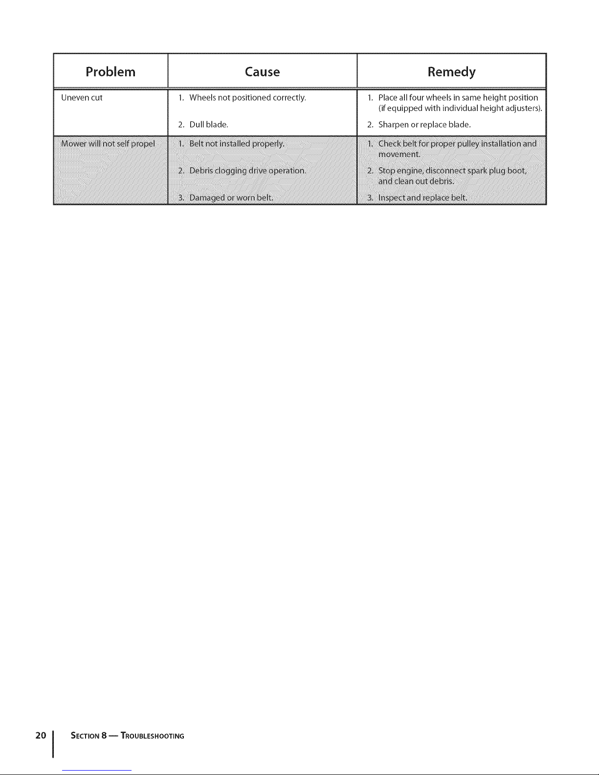
Problem
Uneven cut 1. Wheels not positioned correctly. 1. Place all four wheels in same height position
2. Dull blade. 2. Sharpen or replace blade.
Cause Remedy
(if equipped with individual height adjusters).
i : ifo iii iJi
SECTION 8 -- TROUBLESHOOTING
Page 21

EngineOperation
Fuel Cap
Starter-
Grip
OUFill
Cap
\
\
\
9
Air Cleaner
Spark Plug
Mumer
Figure 9-1
Pre-0perationCheck
Oil Recommendations
NOTE:This engine is shipped without gasoline or oil in the
engine. Running the engine with insufficient oil can cause
serious engine damage and void the engine warranty.
Before starting engine, fill with oil. Do not over-fill. Oil
capacity is about 20 oz.
Use a 4-stroke, or an equivalent high detergent, premium
quality motor oil certified to meet or exceed U.S. automobile
manufacturer's requirements for service classification SG/SF.
Motor oils classified SG/SF will show this designation on the
container.
SAE 10W-30 is recommended for general, all temperature use. If
single viscosity oil is used, select the appropriate viscosity for the
average temperature in your area from the chart to the right.
_ 20w
__ 20
mlmlllmIilmllm
m,3o
2ow4o, _ow5o_____
I
15w40, O_____m/b.
Q lOW40 Iilmmmmlll ml_lmmlmmmmmm
lOw30_____u
(°C)-300 -200 -I0 ° 0° I0 ° 200 300 400
(°F)-20o 0° 200 400 600 800 1000
Ambient Temperature
1. Single Viscosity
2. Multi Viscosity
NOTE: Using non detergent oil or 2-stroke engine oil could
shorten the engine's service life.
21
Page 22

Check0il Level
NOTE: Be sure to check the engine on a level surface with the
engine stopped.
1. Remove the oil filler cap and wipe the dipstick clean. See
Fig. 9-2.
CheckFuelLevel
1. Clean around fuel fill before removing cap to fuel.
2. Fill tank to approximately 1-inch below lowest portion of
neck to allow for fuel expansion. Be careful not to overfill.
NOTE: Before refueling, allow engine to cool 2 minutes.
Starting TheEngine
Oil Fill Cap/
Dipstick
Figure 9-2
2.
Insert the dipstick into the oil filler neck, but do not screw
itin.
3.
If the level is low, slowly add oil to the upper limit on the
dipstick. See Fig. 9-2 inset.
4.
Tighten dipstick firmly before starting engine.
NOTE: Do not overfill. Overfilling with oil may cause
smoking, hard starting, spark plug fouling, or oil saturation
of air cleaner.
FuelRecommendations
Use automotive gasoline (unleaded or low leaded to minimize
combustion chamber deposits) with a minimum of 87 octane,
Gasoline with up to 10% ethanol or 15 _ MTBE (Methyl Tertiary 3.
Butyl Ether) can be used. Never use an oil/gasoline mixture, dirty
gasoline, or gasoline over 30 days old. Avoid getting dirt, dust, or
water in the fuel tank. DO NOT USE E85 GASOLINE.
WARNING: Gasoline is extremely flammable and is
explosive under certain conditions. Refuel in a well-
ventilated area with the engine stopped. Do not
smoke or allow flames or sparks in the area where
the engine is refueled or where gasoline is stored.
Avoid repeated or prolonged contact with skin or
breathing of va pot.
WARNING: Do not overfill the fuel tank (there
should be no fuel in the filler neck). After refueling,
make sure the tank cap is closed properly and
securely. Be careful not to spill fuel when refueling.
Spilled fuel or fuel vapor may ignite. If any fuel is
spilled, make sure the area is dry before starting the
engine.
o
_b ARNING: Always keep hands and feet clear of
1. Push primer 3 times. Wait about two seconds between
2.
equipment moving parts. Do not use a pressurized
starting fluid. Vapors are flammable.
each push. See Fig. 9-3. In temperature below 50°F, prime
5 times. After the engine is warmed up, one prime may be
needed for all temperatures.
Figure 9-3
Standing behind the mower, squeeze and hold the blade
control against upper handle.
Recoil Start: Pull the recoil starter lightly until resistance
is felt, then pull rapidly to overcome compression, prevent
kickback, and start the engine. Repeat if necessary. See Fig.
9-3.
NOTE: Do not allow the recoil starter to snap back against
the rope guide.
Electric Start: Turn ignition key to the right to start the
engine. Release the key after the engine starts. See Fig. 9-3.
If engine does not start, it may be necessary to re-prime
the engine.
StoppingTheEngine
1. Release the blade control.
SECTION 9 -- ENGINE OPERATION
Page 23

EngineMaintenance
_ ARNING: Shut offthe engine before performing
IMPORTANT: If engine must be tipped to transport equipment
or to inspect or remove grass, keep spark plug side of engine
up. Transporting or tipping engine spark plug down may cause
smoking, hard starting, spark plug fouling, or oil saturation of air
cleaner.
MaintenanceSchedule
any maintenance. To prevent accidental start-up,
disconnect the spark plug boot.
1
Periodic inspection and adjustment of the engine is essential
if high level performance is to be maintained. Regular
maintenance will also ensure a long service life. The required
service intervals and the kind of maintenance to be performed
are described in the table below. Follow the hourly or calendar
intervals, whichever occur first. More frequent service is required
when operating in adverse conditions.
_1 WARNING: If the engine has been running, the
muffler will be very hot. Be careful not to touch the
muffler.
FirstSHours
CheckEngineOilLevel
ChangeEngineOilff _/ _/
CheckAirCleaner M/
ServiceAirCleanerf M/
CheckSparkPlug V/
ReplaceSparkPlug V/
CleanEngineShroud V/
Cleanaroundmuffler V/
ReplaceFuelFilter M/
f Service more frequently when used in dusty areas.
ff Every season or 25 hours if operating under heavy load or high ambient temperature.
EachUseor
EveryS Hrs.
,/
EverySeason
or25 Hours
EverySeason
or SOHours
EverySeason
or 100Hours
Service
Dates
23
Page 24

OilService
AirCleanerService
Check oil level regularly.
Be sure correct oil level is maintained. Check every five
hours or daily before starting engine. See oil checking
procedure in the Operation section.
OilChange
IMPORTANT: Be sure to check engine on a level surface with the
engine stopped. Drain the oil while the engine is still warm to
assure rapid and complete draining.
1. Remove all fuel from tank by running engine until it stops
from lack of fuel.
2. Remove drain plug and allow oil to drain into a suitable
container. See Fig. 10-1.
Oil Fill Cap
Paper filters cannot be cleaned and must be replaced once a year
or every 100 operating hours; more often if used in extremely
dusty conditions.
_ WARNING: Never use gasoline or low flash point
IMPORTANT: Never run the engine without the air cleaner. Rapid
engine wear will result.
1. Remove the wing bolt and the air cleaner cover. Remove
solvents for cleaning the air cleaner element. A fire
or explosion could result.
the elements and separate them. See Fig. 10-2. Replace
paper element when dirty or damaged. Clean foam
element or replace when damaged.
f
Figure 10-1
i_ WARNING: Before tipping engine or equipment to
3. Reinstall the drain plug and tighten it securely.
4. Refill with the recommended oil (see Operation section)
5. Reinstall the oil fill cap securely.
IMPORTANT: Used motor oil may cause skin cancer if repeatedly
left in contact with the skin for prolonged periods. Although this
is unlikely unless you handle used oil on a daily basis, it is still
advisable to thoroughly wash your hands with soap and water as
soon as possible after handling used oil.
NOTE: Please dispose of used motor oil in a manner that is
compatible with the environment. We suggest you take it in a
sealed container to your local service station for reclamation. Do
not throw it in the trash or pour it on the ground.
drain oil, drain fuel from tank by running engine
until fuel tank is empty.
and check the oil level. See Fig. 10-1.
Foam Element
Figure 10=2
2. To clean foam element, separate it from the paper element
and wash in liquid detergent and water. Allow to dry
thoroughly before using. Do not oil the foam element.
SECTION10-- ENGINEMAINTENANCE
Page 25

SparkPlugService
_ WARNING: DO NOT check for spark with spark
To ensure proper engine operation, the spark plug must be
properly gapped and free of deposits.
1. Remove the spark plug boot and use a spark plug wrench
i_ WARNING: If the engine has been running, the
2. Visually inspect the spark plug. Discard the spark plug
plug removed. DO NOT crank engine with spark
plug removed.
to remove the plug. See Fig. 10-3.
Spark Plug
Figure 10=3
muffler will be very hot. Be careful not to touch the
muffler.
if there is apparent wear, or if the insulator is cracked or
chipped. Clean the spark plug with a wire brush if it is to be
reused.
3_
Measure the plug gap with a feeler gauge. Correct as
necessary by bending side electrode. See Fig. 10-4. The gap
should be set to 0.030 in.
Electrode
Figure 10-4
4_
Check that the spark plug washer is in good condition
and thread the spark plug in by hand to prevent cross-
threading.
5_
After the spark plug is seated, tighten with a spark plug
wrench to compress the washer.
NOTE:When installing a new spark plug, tighten 1/2 turn
after the spark plug seats to compress the washer. When
reinstalling a used spark plug, tighten 1/8-1/4 turn after the
spark plug seats to compress the washer.
IMPORTANT:The spark plug must be securely tightened.
An improperly tightened spark plug can become very hot
and may damage the engine.
SECTION10 -- ENGINE MAINTENANCE 2S
Page 26

FuelFilter Service
The fuel filter cannot be cleaned and must be replaced once a
year or every 100 operating hours; more often if run with old
gasoline.
1. Remove all fuel from tank by running engine until it stops
from lack of fuel.
2. Remove c-clamp from fuel line and remove fuel line from
tank outlet. See Fig. 10-5.
Storage
Engines stored between 30 and 90 days need to be treated with
a gasoline stabilizer and engines stored over 90 days need to be
drained of fuel to prevent deterioration and gum from forming
in fuel system or on essential carburetor parts. If the gasoline in
your engine deteriorates during storage, you may need to have
the carburetor, and other fuel system components, serviced or
replaced.
1. Remove all fuel from tank by running engine until it stops
from lack of fuel.
Figure 10-5
3. Pull out old fuel filter from tank outlet. Replace when dirty
or damaged.
4. Grasp new fuel filter from shouldered end and insert it
completely to the shoulder into the tank outlet. See Fig.
10-5 inset.
5. Replace fuel line and c-clamp.
CleanEngine
If the engine has been running, allow it to cool for at least half
an hour before cleaning. Periodically remove dirt build-up from
engine. Clean finger guard and around muffler. Clean with a
brush or compressed air.
IMPORTANT'. Do not spray engine with water to clean because
water could contaminate fuel. Using a garden hose or pressure
washing equipment can also force water into the air cleaner or
muffler opening. Water in the air cleaner will soak the paper
element, and water that passes through the element or muffler
can enter the cylinder, causing damage.
_i ARNING: Never leave engine unattended while
2.
3.
4.
5. Store in a clean, dry and well ventilated area away from any
6. If possible, also avoid storage areas with high humidity,
7. Keep the engine level in storage. Tilting can cause fuel or
running.
Change oil. See Oil Change section.
Remove spark plug and pour about 1/2 an ounce of engine
oil into cylinder. Replace spark plug and crank slowly to
distribute oil.
Clean debris from around engine, under finger guard, and
under, around and behind muffler. Touch upany damaged
paint, and coat other areas that may rust with a light film
of oil.
appliance that operates with a flame or pilot light, such
as a furnace, water heater, or clothes dryer. Also avoid any
area with a spark producing electric motor, or where power
tools are operated.
because that promotes rust and corrosion.
oil leakage.
Removing FromStorage
1.
Check your engine as described in the Pre-Operation Check
section of this manual.
2.
If the fuel was drained during storage preparation, fill the
tank with fresh gasoline. If you keep a container of gasoline
for refueling, make certain it contains only fresh fuel.
Gasoline oxidizes and deteriorates over time, causing hard
starting.
3.
If the cylinder was coated with oil during storage
preparation, the engine will smoke briefly at startup. This
is normal.
i_lk WARNING: Accumulation of debris around muffler
could cause a fire. Inspect and clean before every
use.
SECTION10-- ENGINE MAINTENANCE
Page 27

The EZ Start Promise
Provisions of Your Limited Warranty
Inaddition to the other terms and conditions of the Limited Warranty
applicable to your new mower, MTD LLC("MTD") hereby warrants
that your mower's engine will start on the first or second attempt by
an able-bodied adult (subject to the limitations described below) for
the duration of the manufacturer's limited warranty applicable to your .
product. Ifthe engine on your mower fails to conform to this limited
warranty, MTD will cover the cost of parts and labor associated with
any adjustments and/or repairs necessary to return your engine
to its warranted condition. In order to make aclaim under these
provisions of your warranty, you must bring the product and proof of
purchase to an authorized MTD service provider. In many cases,the
retailer who sold you your mower is not equipped to provide warranty
service, so please locate the authorized service dealer nearest you by
either calling the phone number provided in your Operators Manual or
looking up an authorized service dealer on-line at www.mtdproducts.
com.
Items and Conditions Not Covered
The EZStart Promise does not cover and/or apply to the following:
• Cost of regular maintenance service or parts, such asfilters, fuel,
lubricants, oil changes, spark plugs, air filter, bladesharpening,
worn blades, cable/linkage adjustments, or brake and clutch
adjustments
= Transportation costs to and from an authorized MTD service
provider
= Any engine used for commercial, rental, institutional, governmen-
tal, or non-residential applications
= Any product or part that has beenaltered or misused or required
replacement or repair dueto misuse, accidents, or lack of proper
maintenance
• Repairs necessary dueto improper battery care, electrical supply
irregularities, or failure to properly prepare the mower prior to any
period of non-use over three months
= Pickup and/or delivery charges
• Operational misuse, neglect, accidents, unauthorized repairs or
attempted repairs of the engine or its components by anyone other
than an authorized MTD service provider.
Repairs or adjustments to correct starting difficulties dueto any
of the following: failure to follow proper maintenance procedures
-- rotary mower blade striking an object -- contaminants in the
fuel system --improper fuel or fuel/oil mixture (consult your
Operator's Manual if in doubt) -- failure to drain the fuel system
prior to any period of non-use over three months.
Any starting problem which results from the use of inappropriate
fuels, lubricants, or additives.
e
Special conditions or circumstances that normally require more
than two pulls to start, specifically: 1) First start-up following your
initial purchase, 2) first time starts after extended period(s) of
non-use over one month or seasonal storage, 3) cool temperature
starts such as those found in early spring and lateautumn, and 4)
difficult starting that results from the operator's failure to follow
the proper starting procedures identified in the Operator's Manual.
If you arehaving difficulty starting your unit, please check the
Operator's Manual to ensure that you areusing the correct starting
procedures. This can savean unnecessary visit to a Service
Dealer.
Owner Responsibilities
You must maintain your mower (including its engine) byfollowing the
maintenance procedures and starting instructions described in the
Operator's Manual. Such routine maintenance, whether performed by
adealer or by you, is at your expense. In addition, please retain your
proof of purchase and service receipts as these may be requiredto
validate a claim.
General Conditions
An authorized MTD service provider using approved replacement
parts must perform all repairs covered bythe EZ Start Promise.
Repair by an MTD authorized service dealer is your sole remedy
under this warranty. MTD is not liable for indirect, incidental, or
consequential damages in connection with the use of the products
covered by these warranties, including any cost or expense of
providing substitute equipment or service during reasonable periods
of malfunction or non-use pending completion of repairs under this
warranty.
Some states do not allow exclusions of incidental or consequential
damages, or limitations on how long an implied warranty lasts, so
certain exclusions and limitations may not apply to you.
GDO0-100163 Rev.B
Page 28

ReplacementParts
Component _ Part Number and Description
11
1-
951-10292 Spark Plug
951-10298 Air Cleaner Kit
®
0
951-10300
951-10358 Fuel Filter
734-1988 Wheel (Front)
634-04363 Wheel (Rear)
731-04177
\\
\\
964-04134 Grass Bag
Fuel Cap Assembly
Side Discharge Chute
Phone (800) 800-7310 or (330) 220-4683 to order replacement parts or a complete Parts Manual (have your full model number and
serial number ready). Parts Manual downloads are also available free of charge at www.mtdproducts.com
Page 29

Component l Part Number and Description
942-0739 Mulching Blade
954-04158 V-Belt
725-04329 Battery Charger
925-04323 Battery
925-0201 Key
Phone (800) 800-7310 or (330) 220-4683 to order replacement parts or a complete Parts Manual (have your full model number and
serial number ready). Parts Manual downloads are also available free of charge at www.mtdproducts.com
SECTION11 -- REPLACEMENT PARTS 29
Page 30

FEDERALand/orCALIFORNIAEMISSIONCONTROLWARRANTY STATEMENT
YOUR WARRANTY RIGHTS AND OBLIGATIONS
MTDConsumerGroupInc,the UnitedStatesEnvironmentalProtectionAgency (EPA),and,forthoseproductscertifiedforsale in thestateofCalifornia,the
CaliforniaAirResourcesBoard(CARB)are pleasedto explaintheemission(evaporativeand/orexhaust)controlsystem(ECS) warrantyonyouroutdoor2006
andlater smalloff-roadspark-ignitedengineandequipment(outdoorequipmentengine)InCalifornia,new outdoorequipmentenginesmustbe designed,builtand
equippedtomeetthe State'sstringentanti-smogstandards(inotherstates, 1997andlater modelyear equipmentmustbedesigned,built,and equippedto meet
theU.S.EPAsmalloff-road,sparkignitionengineregulations.MTDConsumerGroupIncmustwarrantthe ECSonyouroutdoorequipmentengineforthe periodof
timelistedbelowprovidedtherehasbeen noabuse,neglector impropermaintenanceofoutdoorequipmentengine.
YourECSmayincludepartssuchas thecarburetor,fuel-injectionsystem,the ignitionsystem,catalyticconverter,fueltanks,fuel lines,fuelcaps,valves,canisters,
filters,vaporhoses,clamps,connectors,andotherassociatedemission-relatedcomponents.
Wherea warrantableconditionexists,MTDConsumerGroupIncwill repairyouroutdoorequipmentengineat nocostto youincludingdiagnosis,partsand labor.
MAN UFACTURER'S WARRANTY COVERAGE:
Thisemissioncontrolsystemiswarrantedfortwo years.Ifanyemission-relatedpart onyouroutdoorequipmentengineisdefective,the partwill berepairedor
replacedby MTDCONSUMERGROUPINC.
OWNER'S WARRANTY RESPONSIBILITIES:
Asthe outdoorequipmentengineowner,youareresponsiblefor performanceofthe requiredmaintenancelistedinyourowner'smanual.MTDConsumerGroup
Increcommendsthat youretainallreceiptscoveringmaintenanceonyouroutdoorequipmentengine,butMTDConsumerGroupInc cannotdenywarrantysolely
forthe lackof receipts.
Asthe outdoorequipmentengineowner,youshouldhoweverbe awarethat MTDConsumerGroupIncmaydenyyouwarrantycoverageifyour outdoorequipment
engineor aparthasfailedduetoabuse,neglect,orimpropermaintenanceorunapprovedmodifications.
Youare responsiblefor presentingyouroutdoorequipmentenginetoMTDConsumerGroupInc'sdistributioncenterorservicecenteras soon asthe problem
exists.Thewarrantyrepairsshouldbecompletedin areasonableamountoftime, nottoexceed30 days.Ifyouhaveaquestionregardingyourwarrantycoverage,
youshouldcontacttheMTDConsumerGroupIncService Departmentat 1-800-800-7310orvia emailathttp://support.mtdproducts.com
GENERAL EMISSIONS WARRANTY COVERAGE:
MTDConsumerGroupIncwarrantstothe ultimatepurchaserandeachsubsequentpurchaserthattheoutdoorequipmentengineis: Designed,built andequipped
soasto conformwithall applicableregulations;andfreefromdefectsin materialsandworkmanshipthatcausethefailureofa warrantedpartto be identicalinall
materialrespectstothat partas describedin MTDConsumerGroupInc'sapplicationforcertification.
Thewarrantyperiodbeginsonthedatetheoutdoorequipmentengineis deliveredto anultimatepurchaserorfirst placedintoservice.Thewarrantyperiodistwo
years.
Subjecttocertainconditionsand exclusionsasstated below,thewarrantyonemission-relatedpartsis asfollows:
1. Anywarrantedpartthat isnotscheduledfor replacementasrequiredmaintenanceinthewritteninstructionssupplied,is warrantedforthe warrantyperiod
statedabove.Ifthepart failsduringtheperiodofwarrantycoverage,thepart willberepairedor replacedbyMTDConsumerGroupIncaccordingto subsection
(4)below.Anysuchpart repairedorreplacedunderwarrantywillbewarrantedfortheremainderof the period.
2. Anywarrantedpartthat isscheduledonlyforregularinspectioninthe writteninstructionssuppliedis warrantedforthewarrantyperiodstatedabove.Anysuch
partrepairedor replacedunderwarrantywill bewarrantedforthe remainingwarrantyperiod.
3. Anywarrantedpartthat isscheduledforreplacementasrequiredmaintenanceinthewritteninstructionssuppliediswarrantedfortheperiodof timebeforethe
firstscheduledreplacementdatefor thatpart.If the partfails beforethefirst scheduledreplacement,the partwill berepairedorreplacedbyMTDConsumer
GroupIncaccordingto subsection(4)below.Anysuchpartrepairedor replacedunderwarrantywill bewarrantedforthe remainderof theperiodpriorto the
firstscheduledreplacementpointfor thepart.
4. Repairorreplacementofanywarrantedpart underthewarrantyprovisionshereinmustbeperformedat a warrantystationatno chargetothe owner.
5. Notwithstandingthe provisionsherein,warrantyservicesor repairswillbeprovidedatallof ourdistributioncentersthatarefranchisedtoservicethesubject
enginesor equipment.
6. Theoutdoorequipmentengineownerwill notbe chargedfor diagnosticlaborthatis directlyassociatedwithdiagnosisof a defective,emission-relatedwar-
rantedpart, providedthatsuchdiagnosticworkis performedata warrantystation.
7. MTDConsumerGroupIncisliablefordamagesto otherengineorequipmentcomponentsproximatelycausedby afailure underwarrantyof anywarranted
part.
8. Throughouttheoff-roadengineandequipmentwarrantyperiodstatedabove,MTDConsumerGroupInc willmaintaina supplyofwarrantedpartssufficientto
meetthe expecteddemandforsuchparts.
9. Anyreplacementpartmaybe usedinthe performanceofanywarrantymaintenanceorrepairsand mustbe providedwithoutchargetothe owner.Suchusewill
notreducethe warrantyobligationsof MTDConsumerGroupInc.
10.Add-onor modifiedpartsthatare notexemptedbythe AirResourcesBoardmaynot beused.Theuseofany non-exemptedadd-onor modifiedpartsby the
ultimatepurchaserwillbegroundsfor disallowingawarrantyclaims.MTDConsumerGroup Incwill notbeliable towarrantfailuresof warrantedpartscaused
bythe useof a non-exemptedadd-onormodifiedpart.
Page 31

WARRANTED PARTS:
Therepairorreplacementofanywarrantedpart otherwiseeligiblefor warrantycoveragemaybeexcludedfromsuchwarrantycoverageif MTDConsumerGroup
Incdemonstratesthatthe outdoorequipmentenginehasbeenabused,neglected,orimproperlymaintained,and thatsuchabuse,neglect,or impropermainte-
nancewasthe directcauseof the needfor repairorreplacementofthe part.Thatnotwithstanding,anyadjustmentof a componentthat hasa factoryinstalled,
andproperlyoperating,adjustmentlimitingdeviceisstill eligibleforwarrantycoverage.Further,the coverageunderthis warrantyextendsonly to partsthat were
presentonthe off-roadengineandequipmentpurchased.
Thefollowingemissionwarrantypartsarecovered(ifapplicable):
(1)FuelMeteringSystem
• Cold startenrichmentsystem(softchoke)
• Carburetorand internalparts(orfuel injectionsystem)
• Fuelpump
• Fueltank
(2)Air InductionSystem
• Aircleaner
• Intakemanifold
(3) IgnitionSystem
• Sparkplug(s)
• Magnetoignitionsystem
(4) ExhaustSystem
• Catalyticconverter
• SAI(Reed valve)
(5) MiscellaneousItemsUsedin AboveSystem
• Vacuum,temperature,position,timesensitivevalvesandswitches
• Connectorsandassemblies
(6) EvaporativeControl
• Fuelhose
• Fuelhoseclamps
• Tetheredfuelcap
• Carboncanister
• Vapor lines
GDOC-100223
Page 32

MANUFACTURER'S LiMiTED WARRANTY FOR
The limited warranty set forth below is given by MTD LLC with
respect to new merchandise purchased andused in the United States
and/or its territories and possessions, and by MTD Products Limited
with respect to new merchandise purchased and used in Canadaand/
or its territories and possessions (either entity respectively, "MTD").
"MTD" warrants this product (excluding its Normal WearParts and
Attachments as described below) against defects in material and
workmanship for a period of two (2) years commencing onthe date
of original purchase and will, at its option, repair or replace,free of
charge, any part found to be defective in materials or workmanship.
This limited warranty shall only apply if this product has been
operated and maintained in accordance with the Operator's Manual
furnished with the product, and has not beensubject to misuse,
abuse, commercial use, neglect, accident, improper maintenance,
alteration, vandalism, theft, fire, water, or damage because of other
peril or natural disaster. Damageresulting from the installation or use
of any part, accessory or attachment not approved by MTD for use
with the product(s) covered bythis manual will void your warranty as
to any resulting damage.
Normal WearParts arewarranted to befree from defects in material
andworkmanship for a period of thirty (30) days from the date of
purchase. Normal wear parts include, but are not limited to items
such as: batteries, belts, blades, blade adapters, tines, grass bags,
wheels, rider deck wheels, seats, snow thrower skid shoes, friction
wheels, shaveplates, auger spiral rubber, engine oil, air filters, spark
plugs andtires.
Attachments-- MTD warrants attachments for this product against
defects in material and workmanship for a period of one (1) year,
commencing on the date of the attachment's original purchase or
lease.Attachments include, but are not limited to items such as:
grass collectors and mulch kits.
HOWTO OBTAINSERVICE:Warranty service is available, WITH
PROOFOFPURCHASE,through your local authorized service dealer.
Tolocatethe dealer in your area:
In the U.S.A.
Checkyour Yellow Pages,or contact MTD LLC at RO. Box 361131,
Cleveland, Ohio 44136-0019, or call 1-800-800-7310, 1-330-220-
4683 or log on to our Web site at www.mtdproducts.com.
In Canada
Contact MTD Products Limited, Kitchener, ON N2G4J1, or call 1-800-
668-1238 or log on to our Web site atwww.mtdcanada.com.
This limited warranty does not provide coverage in the following
cases:
a.
Log splitter pumps, valves, and cylinders havea separate one-
yearwarranty.
b.
Routine maintenance items such as lubricants, filters, blade
sharpening, tune-ups, brake adjustments, clutch adjustments,
deck adjustments, and normal deterioration of the exterior finish
dueto use or exposure.
c. Service completed by someone other than an authorized service
dealer.
d. MTD does not extend any warranty for products sold or exported
outside of the United States and/or Canada,andtheir respective
possessions and territories, except those sold through MTD's
authorized channels of export distribution.
e. Replacement parts that are not genuine MTD parts.
f. Transportation charges and service calls.
g. MTD does not warrant this product for commercial use.
No implied warranty, includingany implied warranty of
merchantability of fitness for a particular purpose, applies after
the applicable periodof express written warranty above as to the
parts as identified. No other express warranty, whether written or
oral, except as mentioned above, given by any personor entity,
includinga dealer or retailer, with respect to any product,shall
bind MTD. Duringthe period of the warranty, the exclusive remedy
is repair or replacement of the productas set forth above.
The provisionsas set forth inthis warranty providethe sole and
exclusive remedy arising from the sale. MTDshall not be liable
for incidental orconsequential loss or damage including, without
limitation, expenses incurred for substitute or replacement lawn
careservices or for rental expenses to temporarily replace a
warranted product.
Some states do not allow the exclusion or limitation of incidental
or consequential damages, or limitations on how long an implied
warranty lasts, so the above exclusions or limitations may not apply
to you.
In no event shall recovery of any kind begreater than the amount of
the purchase price of the product sold. Alteration of safety features of
the product shall void this warranty. You assume the risk and liability
for loss, damage, or injury to you and your property and/or to others
andtheir property arising out of the misuse or inability to use the
product.
This limited warranty shall not extend to anyone other than the
original purchaser or to the person for whom it was purchased as a
gift.
HOWSTATELAW RELATESTOTHISWARRANTY: This limited
warranty givesyou specific legal rights, and you may also have other
rights which vary from state to state.
IMPORTANT:Owner must present Original Proof of Purchase to
obtain warranty coverage.
MTD LLC, P.O. BOX 361131 CLEVELAND, OHIO 44136=0019; Phone: 1=800=800=7310, 1=330=220=4683
MTD Canada Limited =KITCHENER, ON N2G 4J1; Phone 1=800=668=1238
GDOC-100016REV. B
Page 33

Medidas importantes de seguridad • Configuraci6n • Funcionarniento • Mantenirniento •Servicio •
Soluci6n de problemas • Garantia
L L
Podadora tipo abonadora autopropulsada m Modelo E18J
MTD LLC, P.O. BOX 361131 CLEVELAND, OHiO 44136-0019
ImpresoenEstadosUnidosdeAmerica
FormularioNo.769-05753
(Diciembre15,2009)
Page 34

A!propietario
Gracias
Gracias por comprar una m_iquina podadora fabricada por
MTD. La misma ha sido diseflada cuidadosamente para brindar
excelente rendimiento si se la opera y mantiene correctamente.
Por favor lea todo este manual antes de operar el equipo.
Le indica c6mo configurar, operar y mantener la m_iquina
con seguridad y flicilmente. Pot favor aseg0rese de seguir
cuidadosamente yen todo momento las pr_icticas de seguridad
recomendadas, y hac_rselas seguir a cualquier otra persona que
opere la m_iquina. En caso de no hacerlo podrian producirse
lesiones personales o dafios materiales.
Toda la informaci6n contenida en este manual hace referencia
a la m_is reciente informaci6n de producto disponible en el
momento de la impresi6n. Revise el manual frecuentemente
para familiarizarse con la unidad, sus caracteristicas y
funcionamiento. Por favor tenga en cuenta que este Manual
del Operador puede cubrir una gama de especificaciones de
productos de diferentes modelos. Las caracteristicas y funciones
indite
1
incluidas y/o ilustradas en este manual pueden no set aplicables
a todos los modelos. MTD se reserva el derecho de modificar
las especificaciones de los productos, los diseffos y el equipo
est_indar sin previo aviso y sin generar responsabilidad por
obligaciones de ning0n tipo.
Este producto cumple con las estrictas normas de seguridad
del Outdoor Power Equipment Institute y de un laboratorio
de pruebas independiente. Si tiene algun problema o duda
respecto a la unidad, Ilame a un distribuidor de servicio MTD
autorizado o p6ngase en contacto directamente con nosotros.
Los numeros de tel_fono, direcci6n del sitio web y direcci6n
postal de la Asistencia al Cliente de MTD se encuentran en esta
p_igina. Queremos garantizar su entera satisfacci6n en todo
momento.
En este manual, las referencias al lado derecho o izquierdo de la
m_iquina se observan desde la posici6n del operador.
/mportante Medidas importantes de seguridad.. 3
Ensamblado y Configuraddn ................................. 9
Controles y Caractefisticas .................................... 12
Funcionamiento ..................................................... 13
Mantenimiento y Ajustes ....................................... 14
Registrodeinformad6ndeproducto
Antes de configura r y operar su equipo nuevo, pot favor Iocalice
la placa del modelo en el equipo y registre la informaci6n en
el _irea situada a la derecha. Para encontrar la placa de modelo,
col6quese detr_is de la unidad en la posici6n del operador y mire
hacia la parte inferior de la secci6n trasera del chasis. Si tiene
que solicitar soporte t6cnico a trav6s de nuestro sitio web, el
Departamento de Asistencia al Cliente, o de un distribuidor de
servicio autorizado local, necesitar_i esta informaci6n.
Servido .................................................................... 16
So/uddn de Problemas ......................................... 20
Fundonamlento de Motor. ................................... 22
Mantenimiento de Motor ..................................... 24
Piezas de Reemp/azo ................. 28 (Manual ingles)
_OMERO DE MODELO
rqDDDDDDDDDD
NOMERO DE SERIE
DDDDDDDDDDD
AsistenciaalCliente
Por favor, NO devuelva la unidad al minorista o distribuidor sin ponerse en contacto primero con el Departamento de
Asistencia al Cliente.
En caso de tener problemas para montar este producto o de tenet dudas con respecto a los controles, fundonamiento o
mantenimiento del mismo, puede solicitar la ayuda de expertos. Elija entre las opciones que se presentan a continuaci6n:
0 Visite nuestro sitioweb en www.mtdproducts.com
0 Llame a un representante de Asistencia al Cliente al (800) 800-7310 6 (330) 220-4683
0 Escribanos a MTD LLC • RO. Box 361131 • Cleveland, OH • 44136-0019
Page 35

Medidasimportantesdeseguridad
ADVERTENCIA: La presencia de este s[mbolo indica que se trata de instrucciones
importantes de seguridad que se deben respetar para evitar poner en peligro su seguridad
personal y/o material y la de otras personas. Lea y siga todas las instrucciones de este manual
antes de poner en funcionamiento esta m_quina. Si no respeta estas instrucciones puede
provocar lesiones personales.
Cuando vea este s[mbolo - iTENGA EN CUENTA LAS ADVERTENCIAS!
PROPOSICION 65 DE CALIFORNIA
ADVERTENCIA: El escape del motor de este producto, algunos de sus componentes y
algunos componentes del vehiculo contienen o liberan sustancias qu[micas que el estado
de California considera que pueden producir c_ncer, defectos de nacimiento u otros
problemas reproductivos.
2
_IL ADVERTENCIA: Los postes de bater[a, los terminales, y los accesorios relacionados
contienen plomo y compuestos de plomo, productos qu[micos conocidos al Estado de
California causar el c_ncer y el dar3o reproductivo. Lave manos despu_s del manejo.
PELIGRO: Esta m_quina est_ diser3ada para set utilizada respetando las normas de seguridad
contenidas en este manual. AI igual que con cualquier tipo de equipo motorizado, un
descuido o error por parte del operador puede producir lesiones graves. Esta m_quina es
capaz de amputar dedos, manos y pies y de arrojar objetos extrarqos con gran fuerza. De no
respetar las instrucciones de seguridad siguientes se pueden producir lesiones graves o la
muerte.
Fundonarniento
Fundonamientogeneral:
1. Lea y siga todas las instrucciones contenidas en este
manual antes de intentar ensamblar esta m_quina. Lea,
comprenda y siga todas las instrucciones que figuran en la
m_quina y en el o los manuales antes de intentar operarla.
Familiaricese completamente con los controles y con el
uso apropiado de esta m_quina antes de operarla. Guarde
este manual en un lugar seguro para referencias futuras y
regulates y para solicitar repuestos.
2. Esta m_quina es una pieza de equipo de precisi6n, no
un juguete. Por tanto, tenga la m_xima precauci6n en
todo momento. Su unidad ha sido dise_ada para realizar
una tarea: cortar el c_sped. No la utilice con ningOn otto
prop6sito.
3. No permita nunca que los ni_os menores de 14a_os
operen esta m_quina. Los ni_os de 14 ahosy m_s deben
leery comprender las instrucciones contenidas en este
manual y deben ser capacitados y supervisados pot uno de
los padres. 0nicamente los individuos responsables que se
hayan familiarizado con estas reglas de seguridad para la
operaci6n deber_n usar esta m_quina.
4. Inspeccione minuciosamente el _rea en donde utilizar_
el equipo. Saque todas las piedras, palos, cables, huesos,
juguetes y otros objetos extra_os con los que podria
tropezar o que podrian set arrojados pot la cuchilla. Los
objetos arrojados pot la m_quina pueden producir lesiones
graves. Planifique el patr6n en el que va air descargando
el recorte para evitar que la descarga de material se
realice hacia los caminos, las veredas, los observadores,
etc. Evite adem_s descargar material contra las paredes
y obstrucciones que podrian provocar que el material
descargado rebote contra el operador.
5_
Para ayudar a evitar el contacto con la cuchilla o una
lesi6n pot un objeto arrojado, mant6ngase en la zona del
operador detr_s de las manijas y mantenga a los ni_os,
observadores, ayudantes y mascotas apartados al menos
25 metros de la podadora mientras est_ en operaci6n.
Detenga la m_quina si alguien entra en la zona.
6_
Para protegerse los ojos utilice siempre anteojos o
antiparras de seguridad mientras opera la m_quina o
mientras la ajusta o repara. Los objetos arrojados que
rebotan pueden lesionar gravemente la vista.
7_
Utilice zapatos de trabajo resistentes, de suela fuerte y
pantalones y camisas ajustados. Se recomienda utilizar
camisas y pantalones que cubran los brazos y las piernas,
asi como calzado con puntas reforzadas en acero. Nunca
opere esta m_quina con los pies desnudos, sandalias, o
con zapatos ligeros o con los que se pueda resbalar (pot
ejemplo, calzado de Iona).
Page 36

8. Nopongalasmanosolospiescercadelaspiezasrotatorias
oenlatolvadelacortadora.Elcontactoconlascuchillas
puedeproducirlaamputaci6ndemanosypies.
9. Unacubiertadedescargafaltanteodahadapuede
provocarelcontactoconlacuchillaolesionesporobjetos
arrojados.
10. Muchaslesionesocurrencomoresultadodepasarla
cortadorasobrelospiesduranteunacaidaprovocadapor
derrapesotropiezos.Nosesostengadelapodadorasise
est_cayendo,sueltelamanijainmediatamente.
11. Nuncatirehaciaustedlapodadoramientrascamina.
Sideberetrocederlapodadoraparaevitarunapared
uobst_culo,mireprimeroabajoyatr_sparaevitar
tropezarseyluegosigaestospasos:
a. Retrocedadelapodadorahastaestirar
completamentesusbrazos.
b. Aseg0resequeest_bienequilibradoybienparado.
c. Tiredelapodadoralentamentehaciausted,no
m&sall&delamitaddeladistanciaentreustedyla
podadora.
d. Repitaestospasoscomoserequiera.
12. Noopereestam&quinaestandobajolosefectosdel
alcoholodedrogas.
13. Noembragueelmecanismodeautopropulsi6nen
unidadesconesteequipomientrasarrancaelmotor.
14. Elmecanismodecontroldelacuchillaesundispositivode
seguridad.Nuncaintentedesviarsedesufuncionamiento.
Dehacerlonofuncionarianlosdispositivosdeseguridady
podrianproducirselesionespersonalesporelcontactocon
lascuchillasgiratorias.Lasmanijasdecontroldelacuchilla
debenfuncionarbienenambasdireccionesyregresar
autom_ticamentealaposici6ndedesengranecuandose
lassuelta.
15.
Nunca opere la podadora en c6sped humedo. Siempre est6
seguro de su equilibrio. Si tropieza y cae puede lesionarse
gravemente. Si siente que pierde el equilibrio, suelte 2.
inmediatamente la manija de control de la cuchilla y la
cuchilla dejar_ de girar en tres segundos.
16.
Corte el c_sped solamente con luz de dia o con una buena 3.
luz artificial. Camine, nunca corra.
17.
Detenga la cuchilla cuando cruce caminos de gravilla,
pasos o andadores.
18.
Si la m_quina comenzara a vibrar de manera anormal,
detenga el motor, y busque inmediatamente la causa.
La vibraci6n por Io general es una advertencia de alg0n
problema.
19.
Apague el motor y espere hasta que la cuchilla se detenga
completamente antes de retirar la guarda para el recorte
de c_sped o desatorar la tolva. La cuchilla continua girando
por unos cuantos segundos despu_s que el motor se ha
apagado. Nunca coloque ninguna parte del cuerpo en el
_rea de la cuchilla hasta que est_ seguro que la cuchilla ha
detenido su movimiento rotatorio.
20. Nuncaoperelacortadorasinlasguardasapropiadas,
cubiertadedescarga,guardapararecorte,manijade
controldelacuchillayotrosdispositivosdeseguridad
yprotecci6nensulugaryfuncionando.Nuncaoperela
cortadorasilosdispositivosdeseguridadest&ndahados.Si
noIohace,estopuedetenercomoresultadolesiones.
21. Elsilenciadoryelmotorsecalientanypuedenproducir
quemaduras.Nolostoque.
22. Utilicesolamentepartesyaccesoriosfabricados
especialmenteparaestam_quina,originalesdelfabricante
(OEM).SinoIohace,esto puede tener como resultado
lesiones personales.
23. Para encender el motor, jale de la cuerda lentamente hasta
que sienta resistencia, luego jale r_pidamente. El repliegue
r&pido de la cuerda de arranque (tensi6n de retroceso) le
jalar_ la mano y el brazo hacia el motor m&s r_pido de Io
que usted puede soltar. El resultado pueden ser huesos
rotos, fracturas, hematomas o esguinces.
24. Si se presentan situaciones que no est&n previstas en este
manual sea cuidadoso y use el sentido com0n. Marque
para contactar el departamento de atenci6n al cliente y
obtener el nombre de su distribuidor m_s cercano.
Funcionamientoenpendientes
Las pendientes son un factor importante que se relaciona con
los accidentes producidos por derrapes y caidas y que pueden
producir lesiones graves. La operaci6n en pendientes requiere
mayor precaucidn. Si no se siente seguro en una pendiente, no
la pode. Para seguridad, use el medidor de pendientes que se
incluye como parte de este manual para medir la pendiente
antes de operar la unidad en una zona inclinada. Si la pendiente
supera los 15 grados, no la pode.
I0siguiente:
Mueva la podadora a trav_s de las caras de la pendiente,
nunca hacia arriba y abajo. Tenga cuidado cuando cambie
de direcci6n cuando opere la m_quina en pendientes.
Est_ atento a los agujeros, raices, rocas, objetos ocultos o
abultamientos que puedan provocar que se derrape o se
tropiece. El c_sped alto puede ocultar obst_culos.
Siempre est_ seguro de su equilibrio. Si tropieza y cae
puede lesionarse gravemente. Si siente que pierde el
equilibrio, suelte inmediatamente la manija de control de
la cuchilla y la cuchilla dejar_ de girar en tres (3) segundos.
Nohaga I0siguiente:
I. No corte el c_sped cerca de pozos, hundimientos, bancos,
podria perder el equilibrio.
2. No pode pendientes mayores de 15 grados como Io indica
el medidor de pendientes.
3. No pode el c_sped h0medo. Si no est_ firmemente parado,
puede resbalarse.
4 I SECCION 2 -- IV_EDIDAS IMPORTANTES DE SEGURIDAD
Page 37

Ni os
Pueden ocurrir accidentes tr_igicos si el operador no est,1 atento
a la presencia de niflos. Por Io general a los niflos les atraen las
podadoras y la actividad de podar el c_sped. No entienden
los riesgos ni los peligros. Nunca d_ por sentado que los niflos
permanecer_in en el mismo lugar donde los vio por Oltima vez.
1. Mantenga a los niflos fuera del _fireade trabajo y bajo
estricta vigilancia de un adulto responsable adem_is del
operador.
2. Est_ alerta y apague la podadora si un niflo ingresa al _irea.
3. Antes y mientras se est,1 moviendo hacia atr_is, mire hacia
atr_is y cuide que no haya niflos.
4. Tenga extrema precauci6n cuando se aproxime a esquinas
ciegas, entradas de puertas, _irboles u otros objetos que
puedan obstaculizarle la vista de un niflo que pudiese
correr hacia la podadora.
5. Mantenga alejados a los niflos de los motores en marcha
o calientes. Pueden sufrir quemaduras con un silenciador
caliente.
6_
Nunca permita que niflos menores de 14aflos operen
esta m_iquina. Los ni_os mayores de 14 aflos deben
leery entender las instrucciones de operaci6n y reglas
de seguridad contenidas en este manual y deben ser
entrenados y supervisados por sus padres.
Servicio
Manejoseguro de la gasolina:
1. Para evitar lesiones personales o daflos materiales sea
sumamente cuidadoso al manipular la gasolina. La gasolina
es altamente inflamable y los vapores son explosivos. Se
puede lesionar gravemente si derrama gasolina sobre
usted o sobre la ropa ya que se puede encender.
2. Utilice s61o recipientes para gasolina autorizados.
3. Nunca Ilene los contenedores en el interior de un vehiculo
o cami6n o caja de camioneta con recubrimientos
pListicos. Coloque siempre los recipientes en el piso y lejos
del vehiculo antes de Ilenarlos.
4_
Retire el equipo a gasolina del cami6n o remolque y II_nelo
en el piso. Si esto no es posible, entonces Ilene dicho
equipo en un remolque con un recipiente port_itil, en vez
de desde un dispensador de gasolina.
5_
Mantenga la boquilla de Ilenado en contacto con el borde
de la entrada del tanque de gasolina o contenedor en todo
momento hasta que est_ Ileno. No utilice un dispositivo
para abrir/cerrar la boquilla.
6_
Apague todos los cigarrillos, cigarros, pipas y otras fuentes
de combusti6n.
7.
Nunca cargue combustible en la m_fiquina en interiores
porque Los vapores inflamables podrian acumularse en el
_irea.
8. Nunca saque la tapa del gas ni agregue combustible
mientras el motor est,1 caliente o en marcha. Deje que el
motor se enfrie por Io menos dos minutos antes de volver a
cargar combustible.
9. Nunca recargue el tanque de combustible. Llene el tanque
no m_is de 1 pulgada (2,5 cm) por debajo de la base del
cuello de Ilenado para dejar espacio para la expansi6n del
combustible.
10.
Vuelva a colocar la tapa de la gasolina y ajOstela bien.
11.
Limpie la gasolina derramada sobre el motor y el equipo.
Traslade la m_iquina a otra zona. Espere 5 minutos antes de
encender el motor.
12. Nunca almacene la m_iquina o el recipiente de combustible
en un espacio cerrado donde haya fuego, chispas o
aparatos con piloto como por ejemplo, calentadores de
agua, calentadores, hornos, secadores de ropa u otros
aparatos a gas.
13. Para reducir el riesgo de incendio mantenga la m_iquina
limpia de pasto, hojas y de acumulaci6n de otros
escombros. Limpie los derrames de aceite o combustible y
saque todos los desechos embebidos con combustible.
14. Deje que la m_iquina se enfrie 5 minutos por Io menos
antes de almacenarla.
Funcionamientogeneral:
1. Nunca encienda un motor en espacios cerrados o en una
zona con poca ventilaci6n. El escape del motor contiene
mon6xido de carbono, un gas inodoro y letal.
2. Antes de limpiar, reparar o inspeccionar la m_iquina,
compruebe que la cuchilla y todas las partes que se
mueven se han detenido. Desconecte el cable de la bujia
y p6ngalo de manera que haga masa contra el motor para
evitar que se encienda de manera accidental.
3. Revise los pernos de montaje de la cuchilla y del motor
a intervalos frecuentes para verificar que est_n bien
apretados. Inspeccione adem_is visualmente la cuchilla
en busca de daflos (abolladuras, desgaste, roturas, etc.).
Reemplace la cuchilla con equipo original del fabricante
(OEM) listado en este manual. "La utilizaci6n de partes que
no cumplan con las especificaciones de equipos originales
podria tener como resultado un rendimiento incorrecto y
adem_is la seguridad podria estar comprometida"
4. Las cuchillas de las podadoras son muy afiladas y podrian
cortarlo. Envuelva la cuchilla o utilice guantes y extreme
precauciones cuando le de servicio.
5. Mantenga todos los pernos, tuercas y tornillos bien
ajustados para asegurarse que la m_iquina se encuentra en
condiciones seguras de operaci6n.
6. Nunca manipule los dispositivos de seguridad de manera
imprudente. Controle peri6dicamente que funcionen de
forma adecuada.
7_
Despu_s de golpear con algun objeto extraflo, detenga
el motor, desconecte el cable de la bujia y conecte el
motor a masa. Inspeccione minuciosamente la m_fiquina
para determinar si est,1 daflada. Repare el daflo antes de
encenderla y operarla.
SECCION _ -- IV_EDIDAS IMPORTANTES DE SEGURIDAD 5
Page 38

8.
Nunca trate de ajustar una rueda o la altura de corte
mientras el motor est_ en marcha.
9.
Los componentes de la tolva para recorte, cubierta
de descarga y escudo de riel, est_n sujetos a desgaste
y dahos que podria dejar expuestas partes que se
mueven o permitir que se arrojen objetos. Para proteger
su seguridad, verifique frecuentemente todos los
componentes y reempl_celos s61o con partes de los
fabricantes de equipos originales (O.E.M.) listadas en este
manual. "La utilizaci6n de partes que no cumplan con las
especificaciones de equipos originales podria tener como
resultado un rendimiento incorrecto y adem_s la seguridad
podria estar comprometida"
10.
No cambie la configuraci6n del regulador del motor ni
acelere demasiado el mismo. El regulador controla la
velocidad m_xima segura de operaci6n del motor.
11.
Verifique frecuentemente la linea de combustible, el
tanque, el tap6n, y los accesorios buscando rajaduras o
p_rdidas. Reemplace de set necesario.
12.
No d_ arranque al motor si no est_ la bujia de encendido.
13.
Mantenga o reemplace las etiquetas de seguridad, segun
sea necesario.
14.
Observe las leyes y normas aplicables para disponer
adecuadamente de los desechos. La descarga inapropiada
de liquidos o materiales puede dahar el medio ambiente.
15.
Seg0n la Comisi6n de Seguridad de Productos para el
Consumidor de los Estados Unidos (CPSC) y la Agencia
de Protecci6n Ambiental de los Estados Unidos (EPA),
este producto tiene una vida dtilmedia de siete (7) ahos,
6 140 horas de funcionamiento. AI finalizar la vida _til
media, adquiera una m_quina nueva o haga inspeccionar
anualmente _sta por un distribuidor de servicio autorizado
para cerciorarse de que todos los sistemas mec_nicos y de
seguridad funcionan correctamente y no tienen excesivo
desgaste. Si no Io hace, pueden producirse accidentes,
lesiones o muerte.
Nomodifique el motor
Para evitar lesiones graves o la muerte, no modifique el motor
bajo ninguna circunstancia. Si cambia la configuraci6n del
regulador el motor puede descontrolarse y operar a velocidades
inseguras. Nunca cambie la configuraci6n de f_brica del
regulador del motor.
Avisoreferidoa emisiones
Los motores que est_n certificados y cumplen con las
regulaciones de emisiones federales EPA y de California para
SORE (Equipos peque_os todo terreno) est_n certificados para
operar con gasolina comOn sin plomo y pueden incluir los
siguientes sistemas de control de emisiones: Modificaci6n de
motor (EM) y catalizador de tres vias (TWC) si est_n equipados de
esa manera.
Guardachispas
ADVERTENCIA: Esta m_quina est_ equipada con
un motor de combusti6n interna y no debe ser
utilizada en o cerca de un terreno agreste cubierto
por bosque, malezas o hierba excepto si el sistema
de escape del motor est_ equipado con un
amortiguador de chispas que cumpla con las leyes
locales o estatales correspondientes, en caso de
haberlas.
Si se utiliza un amortiguador de chispas el operador Io debe
mantener en condiciones de uso adecuadas. En el Estado
de California las medidas anteriormente mencionadas son
exigidas pot ley (Articulo 4442 del C6digo de Recursos Publicos
de California). Es posible que existan leyes similares en otros
estados. Las leyes federales se aplican en territorios federales.
Puede conseguir el amortiguador de chispas para el silenciador
a trav_s de su distribuidor autorizado de motores o poni_ndose
en contacto con el departamento de servicios, P.O.Box 361131
Cleveland, Ohio 44136-0019. (Servicio v_lido s61o en E.U.A.)
6 I SECCION 2 -- IV_EDIDAS IMPORTANTES DE SEGURIDAD
Page 39

SimbolosDeSeguridad
Esta p_igina representa y describe la seguridad los simbolos que pueden parecer en este producto. Lea, comprenda, y siga todas
instrucciones de la m_iquina antes de intentar ensamblar y operar.
LEA ELMANUAL(S) DEL OPERADOR
Lea, comprenda, y siga todas instrucciones en el manual (manuales) antes de operar el
prod ucto.
PELIGRO-- GIRANDO HOJAS
Para reducir el riesgo de herida, guarde manos y pies lejos. No haga funcionar a menos que la
tapa de descarga o el receptor de hierba est_n en su lugar apropiado. De ser dahado, sustituya
inmediatamente.
®
i|1_
IRFS
__ PELIGRO-- CORTE DE PIE
No siegue cuando los ni_os o los otros est_n alrededor.
Guarde manos y pies lejos de las cuchillas giratorias.
PELIGRO-- ESCOMBROS LANZADOS
Quite objetos que pueden set lanzados pot la I_imina en cualquier direcci6n. Lleve galas de
seguridad.
PELIGRO-- CUESTAS
Tenga mucha precauci6n en pendientes. No siegue cuestas mayores que 15 o
_ __11 _ ADVERTENCIA-INCENDIO
,_ Para reducir el riesgo de incendio mantenga la m_iquina limpia de pasto, hojas y de
__\_%._ operaci6n. Permita que se enfrien el motor y el silenciador antes de tocarlos.
acumulaci6n de otros escombros.
ADVERTENClA VAPORES TOXlCOS
Nunca encienda un motor en espacios cerrados o en una zona con poca ventilaci6n. Elescape
del motor contiene mon6xido de carbono, un gas inodoro y letal.
ADVERTENCIA -- SUPERFICIE CALIENTE
Las partes del motor, especialmente el silenciador, Ilega a set muy caliente durante la
comprendan y respeten las advertencias e instrucciones que figuran en este manual yen la m_fiquina.
I_l ADVERTENCIA: Su responsabilidad--Restrinja el uso de esta m_iquina motorizada alas personas que lean, |
GUARDEESTASINSTRUCCIONES
SECCION '_ -- JV_EDIDAS IMPORTANTES DE SEGURIDAD 7
J
Page 40

N
E
c_
0
CL_
0
c5
I
I
I
I
0
m
0
l
l
l
l
l
l
l
l
l
l
l
l
l
o
I
I
0
I
I
I
I
I
E
I
_n
I
I
I
SECCION '_ -- JV_EDIDAS IMPORTANTES DE SEGURIDAD
Page 41

MontajeyConfiguraci6n
Contenidodeiacaja
3
Una Podadora
Uno Manual de Operador
Uno Colector de C_sped
Uno Canal de Descarga Lateral
Montaje
NOTA: Esta unidad se envia sin gasolina ni aceite en el motor.
Llene con gasolina y aceite como se indica en las instrucciones
que se incluyen en el manual de motor adjunto ANTES de poner
en funcionamiento su podadora.
Manija
1. Retire el colector de c6sped y material de empaque que
pudiera estar entre las manijas superior e inferior.
a. Retire las perillas manuales de los soportes de
montaje de la manija y tire y retroceda la manija
superior como se muestra en la Figura 3-1.
Asegurese de que la manija inferior est_ asentada
firmemente en los soportes de montaje de la manija.
b. Apriete las perillas manuales que sujetan la manija
superior a la manija inferior. Asegurese de que el
bul6n de carro est_ apropiadamente asentado en la
manija.
Uno Botella del Aceite
Figura 3-2
3.
La guia de la cuerda est_ unida al costado derecho de la
manija superior. Afloje la tuerca de mariposa que sujeta la
guia de la cuerda, Figura 3-3.
J
Figura 3-1
2. Vuelva a colocar y apriete las perillas manuales extraidas
antes asegurando la manija inferior a los soportes de la
manija, Figura 3-2.
Figura 3-3
Page 42

a. Sostenga el control de la cuchilla contra la manija
superior.
b. Jale lentamente la cuerda de arranque para sacarla
del motor. Suelte el control de la cuchilla.
c. Deslice la cuerda de arranque en la guia.
d. Ajuste la tuerca mariposa.
4.
Asegure los cables a la manija inferior utilizando la uni6n
del cable. Tire de las uniones del cable apret_ndolas y
recortando el exceso.
C01ect0rde C_sped
1. Para ensamblar el colector de c_sped (de set necesario),
Haga el cierto bolso es clio vuelta a la derecha el lado antes
de reunir (la advertencia de la etiqueta ser_ por fuera).
a. Coloque la bolsa sobre el marco con el lado negro de
pl_stico en el rondo, Figura 3-4.
b. Deslice el canal de pl_stico sobre los ganchos del
marco. Todos los canales excepto la parte superior
central de la bolsa se acoplan clesde el exterior.
F
Figura 3=S
3.
Para acoplar el colector de c&sped, Figura 3-6.
a. Levante la puerta de descarga posterior.
b. Coloque el colector de c_sped en la varilla de pivote.
Suelte la puerta de descarga de modo que descanse
sobre el colector de c&sped.
k. j
Figura 3=4
c. El centro de la bolsa se acopla desde el interior.
2.
Antes de acoplar el colector de c_sped, la tolva de abono
debe extraerse, Figura 3-5.
a. Levante la puerta de descarga posterior.
b. Extraiga la tolva de abono.
SECCION3-- MONTAJE Y CONFIGURACION
J
Figura 3=6
Para quitar al receptor de hierba, levante la puerta de descarga
trasera en el cortac_sped. Receptor de hierba de levantamiento
y, lejos de la vara de pivote. El reverso de liberaci6n descarga
la puerta para permitir que ello cerrara la apertura trasera del
cortac_sped.
Page 43

ADVERTENCIA: Nunca opere la podadora a
menos que los ganchos del colector de c_sped est_n
firmemente asentados en Ins ranuras de los
montajes de la m_nsula de la manija y la puerta de
descarga posterior descanse firmemente contra la
parte superior del colector de c_sped.
CanaldeDescargaLateral
Si hace la conversi6n a descarga lateral, asegurese de que el
colector de c_sped est_ fuera de la unidad y que la puerta de
descarga trasera est_ cerrada.
1. Sobre el lateral de la podadora, eleve la clavija de abono.
2. Deslice los dos ganchos del canal de descarga lateral
debajo del pasador en el montaje de la clavija para abono
y baje la clavija para abono lateral, Figura 3-7. No extraiga
la clavija para abono lateral en cualquier momento, nun
cuando no est_ abonando.
Ajustes
Ajustedelaaltura de c0rte
1. La palanca de ajuste de altura de corte se ubica pot encima
de la rueda izquierda trasera, Figura 3-8.
r
Figura 3=7
Figura 3=8
a. Tire de la palanca hacia afuera de la podadora.
b. Mueva la palanca hacia adelante o hacia atr_is para la
altura de corte deseada.
c. Suelte la palanca hacia la cubierta de la podadora.
Configuraci6n
Llenadodegasolina yaceite
Refi_rase a la secci6n de motor en este manual para la
informaci6n de motor.
1. A_adir el petr61eo proporcionado antes de la unidad inicial
pot primera vez de la caja.
2. Atender el motor con la gasolina como instruido en la
secci6n de motor de este manual.
manipule gasolina. La gasolina es altamente
_ DVERTENCIA: Tenga extremo cuidado cuando
3. Bateria de precio como instruido en la seccidn de Servicio
inflamable y sus vapores pueden causar
explosiones. Nunca agregue combustible a la
m_iquina en interiores o mientras el motor est,1
caliente o en funcionamiento. Apague cigarrillos,
cigarros, pipas y otras fuentes de combustidn.
de este manual (Unidades de Principio El_ctricas).
SECCION3 -- MONTASE Y CONFIGURACION 11
Page 44

ControlesYCaracter sticas
Arrancador
de retroceso
Control de la transmisi6n
de cuchilla
Palanca de
ajuste de altura
de torte
Cebador
J
4
Clavija para
Figura 4=1
Controlde Cuchiila
El control de la cuchilla est_ unido a la manija superior. Presione
la manija de control de la cuchilla contra la manija superior para
operar la unidad. Suelte la manija de control de la cuchilla para
detener el motor y la cuchilla.
_ DVERTENCIA: El mecanismo de control de la
cuchilla es un dispositivo de seguridad. Nunca
intente anular su funcionamiento.
Controlde iaTransrnisi6n
El control de la transmisi6n est_ ubicado sobre la parte de
abajo de la manija superior y se utiliza para engranar la
transmisi6n. Apri_telo contra la manija superior para enganchar
la transmisi6n; lib_rela para aminorar la velocidad o detener la
podadora. Vea la fig. 4-1.
PalancadeAjustedeia Aiturade Corte
La palanca de ajuste de altura de corte se ubica por encima de la
rueda izquierda trasera. Para ajustar la altura de corte, consulte la
Secci6n de Ajuste.
J
ClavijaParaAbono
El adaptador para abono se utiliza unicamente para prop6sitos
de abono. En vez de recolectar los recortes del c_sped en un
colector de c_sped o canal de descarga lateral, algunos modelos
de podadora tienen la opci6n de recircular los recortes en el
c_sped. Esto se llama abonar.
Arrancadorei_ctrico
El interruptor de encendido est_ Iocalizado en el lado izquierdo
del panel de la manija del arrancador el_ctrico. Es usado s61o
para eljuez de salida el_ctrico.
Cebador
El cebador es Iocalizada en el lado izquierdo
del motor, detr_s del filtro de aire. AI
presionar el cebador se envia combustible
directamente al carburador del motor para
ayudar al encendido el motor.
ArrancadordeRetroceso
El arrancador de retroceso est_ unido a la manija superior
derecha. Para encender la unidad col6quese detr_s de la misma y
tire de la cuerda del arrancador de retroceso.
Page 45

Funcionamiento
Encendidodei Motor
ADVERTENCIA: Asegurese que ninguna persona
aparte del operador permanezca cerca de la
podadora mientras arranca el motor u opera la
misma. Nunca encienda un motor en espacios
cerrados o en una zona con poca ventilaci6n. El
escape del motor contiene mon6xido de carbono,
un gas inodoro y letal. Mantenga las manos, los pies,
el cabello y la ropa suelta alejados de las partes
mdviles del motor y de la podadora.
1.
Oprima el cebador 3 veces. Espere aproximadamente dos
segundos entre cada presidn. Vea la fig. 5-1. En climas con
temperaturas de abajo de 50°!:, optima el cebador 5 veces.
Despu_s de que el motor es calentado, un tiempo puede
ser necesario para todas las temperaturas.
2.
Coldquese detr_is de la podadora, apriete la manija de
control de la cuchilla y sost_ngala contra la manija superior.
Ver la Fig. 5-1.
3,
Arrancador de retroceso: Tire suavemente de la
empuEadura del arranque hasta sentir la resistencia, luego
tire r_ipidamente para reducir la compresi6n, impedir la
tensi6n de retroceso y arrancar el motor. Repita de ser
necesario. Vea la Fig. 5-1.
IMPORTANTE: No permita que el juez de salida de
retroceso se rompa atr_is contra la guia de cuerda.
Arrancador el_ctrico: Gire la Ilave de encendido a la
derecha para poner en marcha el motor. Suelte la Ilave una
vez que el motor se ha puesto en marcha. Vea la Fig. 5-1.
Si el motor no comienza, repita pasos 1-3.
Detenci6ndelMotor
1. Suelte la manija de control de la cuchilla para detener el
motor y la cuchilla.
ADVERTENCIA: Espere a que la cuchilla se haya
detenido pot completo antes de hacer cualquier
trabajo en la podadora o de retirar el colector de
c_sped.
gsodeia PodadoradeC sped
Aseg0rese que el c_sped est,1 libre de piedras, palos, cables u
otros objetos que pudiesen dahar la cortadora o el motor. Dichos
objetos pueden set arrojados accidentalmente pot la podadora
en cualquier direcci6n y provocar lesiones personales graves al
operador y a otras personas.
ADVERTENCIA: AI operar una podadora puede
ser que objetos extrar_os sean arrojados a los ojos, Io
cual puede daharlos gravemente. Utilice siempre
galas de seguridad durante la operaci6n de la
podadora o mientras la ajusta o la repara.
1.
Una vez que el motor est_ funcionando, apriete el control
de transmisi6n contra la manija superior para propulsar la
podadora.
Figura 5=1
_ DVERTENCIA: Si golpea un objeto extra,o,
detenga el motor. Retire el cable de la bujia,
inspeccione la podadora para ver que no tenga
dahos, y repare el daEo antes de reiniciar y operar la
podadora. La vibraci6n excesiva de la podadora
durante la operaci6n es una indicaci6n de daEo. Se
debe inspeccionar y reparar la unidad Io antes
posible.
UsocomoAbonadora
Para abonar el c6sped, quite el colector de c6sped de la m_iquina.
La puerta de descarga posterior deber_i estar cerrada. Para
un abono eficiente, no corte c6sped humedo. Si el c6sped ha
crecido m_is de 10,2 cm. (4 pulg.) no se recomienda el uso de
la podadora como abonadora. Enese caso, use el colector de
c6sped para embolsar los recortes.
UsodeiColectordeC sped
Puede utilizar el colector de c6sped para recoger dichos recortes
mientras opera la podadora.
1. Acople el colector de c_sped siguiendo las instrucciones
en la secci6n de Montaje y Configuraci6n. Los recortes
de c_sped se recolectar_in autom_iticamente en la bolsa a
medida que pase la podadora. Opere la podadora hasta
que la bolsa de recolecci6n est6 Ilena.
2. Detenga el motor por completo soltando la manija de
control de la cuchilla. Compruebe que la unidad se haya
detenido por completo.
3. Para deshacerse de los recortes de c_sped levante la puerta
de descarga y tire de la bolsa de recolecci6n hacia arriba,
apart_indola de la podadora.
13
Page 46

MantenimientoYAjustes
6
Mantenimiento
RecomendadonesGenerales
Respete siempre las reglas de seguridad cuando realice
tareas de mantenimiento.
La garantia de esta podadora no cubre elementos que han
estado sujetos al mal uso o la negligencia del operador.
Para recibir el reembolso total de la garantia, el operador
deber_ dar mantenimiento a la podadora como se indica
en este manual.
El cambio de la velocidad controlada del motor invalidar_
la garantia del motor.
Todos los ajustes deben set verificados pot Io menos una
vez en cada estaci6n.
Revise peri6dicamente todos los sujetadores y compruebe
que est6n bien ajustados.
ADVERTENCIA: Detenga siempre el motor,
desconecte la bujia y haga masa contra el motor
antes de realizar cualquier tarea de mantenimiento a
su m_quina.
Lubrkad6n
1.
Lubrique con aceite ligero los puntos de pivote del control
de la cuchilla y la transmisi6n al menos una vez cada
estaci6n. Los controls debe funcionar libremente en ambas
direcciones, Fig. 6-1.
2.
Lubrique las ruedas pot Io menos una vez pot temporada
con aceite ligero o aceite para motor. Sin embargo, si las
ruedas se quitan pot cualquier raz6n, debe lubricar la
superficie del brazo giratorio y la superficie interna de la
rueda con aceite ligero, Fig. 6-1.
3. Lubrique el resorte de torsi6n y el punto de pivote de
la puerta trasera de descarga y clavija de abono lateral
peri6dicamente con aceite ligero para prevenir la
oxidaci6n, Fig. 6-1.
4. La transmisi6n es prelubricada y sellada en la f_brica y no
requiere la lubricaci6n.
5. Siga la secci6n de Mantenimiento de Motor para lista de
lubricaci6n e instrucci6n para la lubricaci6n de motor.
Cuidad0de lacubierta
Debe limpiar la parte inferior de la plataforma de la podadora
despu_s de cada uso para prevenir la acumulaci6n de recortes
de c_sped u otros desechos. Siga los pasos que aparecen debajo
para realizar esta tarea.
1. Desconecte el cable de la bujia. Drene la gasolina de la
podadora o coloque un trozo de pl_stico debajo del tap6n
de Ilenado del combustible.
2.
Incline la podadora de manera que quede apoyada sobre la
caja. Mantenga hacia arriba el lado donde se encuentra el
filtro de aire. Sostenga firmemente la podadora.
ADVERTENCIA: Nunca incline la podadora m_s de
90 grados en ninguna direcci6n y no deje la
podadora inclinada. Se puede filtrar aceite dentro
de la parte superior del motor y causar problemas
de arranque.
3.
Raspe y limpie la parte inferior de la plataforma mediante
el uso de una herramienta adecuada. No la rocie con agua.
4.
Vuelva a colocar la podadora sobre sus ruedas en el
suelo. Si puso un pl_stico debajo del tap6n de Ilenado de
combustible asegurese de sacarlo en este momento.
Cuidadosparael motor
NOTA: Refi_rase alas secciones de mantenimiento y operaci6n
de motor en este manual para instrucciones detalladas.
Verifique el nivel de aceite.
Limpie el filtro de aire cada 25 horas en condiciones
normales de uso. Limpie a intervalos de pocas horas
cuando haya mucho polvo.
Limpie la bujia y restablezca la distancia disruptiva por Io
menos una vez por temporada.
Limpie el motor regularmente con un trapo o cepillo.
Mantenga limpio el sistema de enfriamiento (_rea del
soplador) para permitir la circulaci6n apropiada de aire.
Quite todo el c_sped, suciedad y residuos combustibles del
_rea del silenciador.
Figura 6-1
Page 47

Reemplazodealer6n trasero
1. Para quitar la tapa trasera, levante lapuerta trasera, quite
el tornillo, y la tapa de prensa en a ambos lados para quitar
del agujero. Ver la Fig. 6-2.
2. Quite el tornillo y la tapa del agujero de enfrente y
sustituya por la nueva tapa en la orden de enfrente y la
manera del retiro.
Ajustes
CaNede Pase0
Su unidad es equipada con un cable de paseo ajustable para
ajustar la tensi6n en el cable de paseo. Usted tendr_ que ajustar
el cable de paseo siel cortac6sped no se propulsa con el control
de paseo contratado o si las ruedas del cortac6sped vacilan
con el control de paseo contratado. Si cualquiera de estas
condiciones ocurre, hace girar el barril de ajustador- fabricaci6n
esto m_s largo dar_ m_s paseo y la mantequilla de ello dar_
menos. Estetambi6n aumentar_ o disminuir_ lafuerza requerida
contratar el control de paseo. Vea la Fig.6-3.
Figura 6=2
J
Figura 6-3
SECCION 6 -- MANTENiMIENTO Y AJUSTES 15
Page 48

Servido
7
Cuidadode iaCuchUla
ADVERTENCIA: Cuando saque la cuchilla de corte
para afilarla o reemplazarla, prot_jase las manos
usando un par de guantes para trabajo rudo o un
trapo grueso para sostener la cuchilla. Inspeccione
peri6dicamente el adaptador de la cuchilla en busca
de rajaduras, especialmente cuando golpee un
objeto extraho. Realice los reemplazos que resulten
necesarios. Siga los pasos que aparecen debajo para
realizar el mantenimiento de la cuchilla.
1. Desconecte el cable de la bujia. Gire la podadora sobre el
costado y compruebe que el filtro de aire y el carburador
queden mirando hacia arriba.
2. Saque el perno y el soporte de campana de la cuchilla que
sostienen la cuchilla y el adaptador de la misma al cig0e_al
del motor, Fig. 7-1.
Cuchilla
Adaptador de la
Misma
Soporte de
Campana de .........
la Cuchilla
...... _____l_ _
J
Y
/-
Perno
5. Lubrique el cig0e_al del motor y la superficie interna
del adaptador de la cuchilla con aceite ligero. Deslice el
adaptador de la cuchilla sobre el cig0e_al del motor. Instale
la cuchilla con el lado marcado "Bottom" (inferior) o con el
numero de parte hacia el piso cuando la podadora est_ en
posici6n de operaci6n. Asegurese que la cuchilla quede
alineada y asentada en las bridas del adaptador.
6. Coloque el soporte de campana de la cuchilla en la misma.
Compruebe que las muescas del soporte de campana de
la cuchilla est_n alineadas con los orificios peque_os de la
cuchilla.
7. Vuelva a colocar el perno hexagonal y ajustelo segun Los
siguientes valores de torsidn: 450 Ib-pulg como minimo,
600 Ib-pulg como m_ximo.
Para asegurar la operaci6n segura de la podadora revise
peri6dicamente el perno de la cuchilla para determinar si est_
bien ajustado.
Cuidadode la correa
1.
Desconecte el cable de la bujia y conecte a tierra contra el
motor.
2.
Drene el tanque de combustible o coloque una pieza de
pl_stico pot debajo de la tapa para evitar una p_rdida de
gasolina.
3.
Incline la podadora sobre su costado (el lado del filtro de
aire del motor hacia arriba).
4.
Quite la cuchilla, el adaptador de cuchilla y partes
met_licas asociadas, Fig. 7-1.
a. Quite los tornillos autoroscante que asegura la tolva
de motor a la cubierta, Fig. 7-2. Quite la tolva de
motor.
F
Figura 7-1
3.
Saque la cuchilla y el adaptador del cig0e_al, Fig. 7-1.
4.
Para comprobar el equilibrio, retire la cuchilla y balancee
sobre un destornillador de eje redondo. Saque metal del
lado pesado hasta que quede bien equilibrada. Cuando
afile la cuchilla, siga el _ngulo original de la muela como
guia. Afile cada borde de corte pot igual para mantener el
balance de la cuchilla.
ADVERTENCIA: Si la cuchilla est_ desequilibrada
generar_ vibraciones excesivas cuando rote a altas
velocidades. Esto puede producir da_os a la
podadora, y se puede romper, causando asi lesiones
personales.
'°1
Figura 7-2
Page 49

b. Afloje el tornillo autoroscante que asegura la tolva
de la cubierta a la cubierta, Fig. 7-2.
c. Desde la parte posterior de la podadora, con
cuidado quite la correa de la polea de transmisidn,
Fig. 7-3.
d. Una vez que la correa est_ fuera de la polea de
transmisidn, empuje sobre la tolva de la cubierta
para acceder a la polea del motor y deslice la correa
fuera de esta polea y fuera de la cubierta, Fig. 7-3.
Reeaplazode ia bateda
_L DVERTENCIA: Las baterias contienen _icido
1. Afloje las perillas de la manija asegurando las manijas
sulfurico que puede causar quemaduras. No ponga
en corto circuito o mutile las baterias de ninguna
manera. No coloque las baterias sobre fuego dado
que pueden explotar o despedir materiales t6xicos.
inferior y superior y con cuidado doblando la manija
superior hacia la manija inferior como se muestra en la Fig.
7-4.
/ff
//
/
/
\
\
Figura 7-3
5.
Reemplace por una nueva correa, coloc_indola entre
la cubierta y la tolva, primero alrededor de la polea de
transmisi6n y luego la polea del motor.
NOTA: AsegOrese de que la correa est_ correctamente
asentada y que se mueve sin problemas en la polea del
motor y no quede atrapada entre las mitades inferior y
superior de la polea.
6.
Apriete el tornillo de autogolpeado que asegura la tolva de
cubierta soltada antes.
7.
Sustituya la tolva de motor y seguro con mi tornillos que
dan un toque.
8.
Reemplace la cuchilla, el adaptador de cuchilla y partes
met_licas asociadas. Siga instrucciones en la secci6n de
Cuidado de L_mina para la asamblea apropiada.
9.
Vuelva a colocar a la podadora en posici6n vertical sobre
sus ruedas y quite el trozo de pl_stico por debajo del
casquete de gas (en caso de corresponder).
\
\
Figura 7=4
2.
Retire los dos tornillos asegurando la cubierta de la bateria
al alojamiento de la bateria y coldquelos hacia el lateral,
Fig. 7-4.
3.
Abra la cubierta de la bateria, quite los conductores
positivos y negativos de la bateria, quite y reemplace por
una nueva bateria. Conecte el conductor positivo al lado
positivo del paquete de bateria, luego conecte el lado
negativo.
SEGCION7 -- SERVlCIO 17
Page 50

NOTA: La bateria que tiene puede diferir ligeramente de la
que se muestra en la Fig. 7-5. Consulte la lista de piezas.
f
+
Terminal
Positivo
Terminal
,J
Figura 7-5
IMPORTANTE: Cuando reemplace el paquete de baterias
en el panel de la manija, el paquete de baterias debe estar
posicionado con el terminal positivo hacia el lado izquierdo
y el terminal negativo hacia el lado derecho del panel (el
terminal positivo est_ m_s cerca de la Ilave de contacto),
Fig. 7-5. El reemplazo incorrecto de la bateria causar_ serios
dahos.
4. Vuelva a colocar la cubierta de la bateria al alojamiento
de la bateria fijando los dos tornillos que sac6 antes,
asegur_ndose de que coloque a presi6n el conducto de
alambre a la izquierda en su lugar en el alojamiento.
5. Doble las manijas y apriete las perillas de la manija.
Cargade ia bateria
_lk DVERTENCIA: La bateria contiene fluido
-- desensamble, mutile o prenda fuego a la bateria. Los
corrosivo y material t6xico; manipule con cuidado y
mantenga alejado de los ni_os. No perfore,
gases explosivos podrian purgarse durante la carga
o descarga. Utilice en un _rea bien ventilada, alejada
de las fuentes de ignici6n.
NOTA: La clavija especialmente dise_ada del cargador
unicamente se adaptar_ a la clavija en la caja de las
baterias.
1. Enchufe el cargador de la bateria dentro del orificio en la
parte inferior del alojamiento de la bateria, Fig. 7-6.
F
Figura 7-6
2_
Inserte la clavija del cargador de la bateria en una salida
residencial est_ndar de 120 voltios. Cargue la bateria
durante 8a 10 horas antes del uso inicial. No cargue por
m_s de 12 horas.
NOTA: Para el motor 6ptimo interpretaci6n inicial y
duraci6n de la pila, cobre la bateria durante 8a 10 horas
despu_s de cada uso o hasta que la luz CONDUClDA verde
en el cargador ilumine (De set equipado). No cargue pot
m_s de 12 horas.
3_
Despu6s de cargar, primero desconecte la clavija del
cargador de la salida, luego desconecte el conductor del
cargador de la bateria.
IMPORTANTE: No quite el paquete de baterias del
alojamiento del arrancador el_ctrico por ninguna razdn
que no sea el reemplazo.
IMPORTANTE: Siempre conecte el conductor del cargador
dentro del paquete de baterias en primer lugar, y luego
inserte la clavija del cargador de baterias en una salida
residencial est_ndar de 120 voltios. Siga este orden siempre
que cargue la bateria.
SEGCION7-- SERVlCIO
Page 51

Reemplazodelfusible
El circuito del arrancador el_ctrico y la bateria est_in protegidos
pot un fusible de 40 amperes. Si el fusible se quema, el
arrancador el_ctrico no funcionar_i. Si la unidad no se enciende
con el arrancador el_ctrico, siga los siguientes pasos para
verificar que el fusible est,1 dentro del alojamiento de la bateria:
1. Abra la cubierta de la bateria como se describe en
Reemplazo de Bateria, ver Fig. 7-4.
2. Retire el fusible del enchufe e inspeccione como se
muestra en la Fig. 7-7. Si est_fiquemado, reemplace por un
fusible de autom6viles est_indar de 40 amperes.
AimacenamienteFueradeTemporada
Se deben seguir estos pasos para la preparaci6n de la podadora
para su almacenamiento.
Limpie y lubrique la podadora como se describe en Las
instrucciones de lubricaci6n.
No utilice una lavadora a presi6n o manguera de jardin
para limpiar su unidad.
Cubra la cuchilla con grasa para chasis para impedir la
oxidaci6n.
Almacene la unidad en una zona limpia y seca. No la
almacene cerca de materiales corrosivos como por ejemplo
fertilizantes.
Cuando almacene cualquier tipo de equipo motorizado en UN
galp6n de dep6sito met_ilico o con poca ventilaci6n, tenga
especial cuidado de realizarle un tratamiento antioxidante al
equipo. Use aceite ligero o silicona para recubrir el equipo,
especialmente los cables y partes m6viles de su podadora antes
de almacenarla.
Bateria
La bateria debe guardarse con una carga completa. El
almacenamiento prolongado de una bateria descargada reducir_i
la vida Otil y la capacidad de la bateria.
Figura 7-7
3.
Coloque con cuidado los cables dentro del alojamiento,
cierre la tapa de la bateria y doble la manija superior
nuevamente en su lugar.
NOTA: El motor puede ponerse en marcha manualmente si
el fusible se quema.
SECCION7 -- SERVlCIO 19
Page 52

Soluci6ndeproblemas
Problema Causa J Remedio
El motor funciona de
manera err_itica
Saltos ocasionales
(pausas) a
alta velocidad
1. El cable de la bujia est,1 flojo.
2. La linea del combustible est,1 tapada o el
combustible es viejo.
3. La ventilaci6n en la tapa del combustible
est,1 obstruida.
4.
Agua o suciedad en el sistema del
combustible.
5. Elfiltro de aire est,1 sucio.
6.
La unidad que corre con el ESTARTER(De set
equipado) se aplic6.
La distancia disruptiva de la bujia es muy
peque_a.
1. Conecte y ajuste el cable de la bujia.
2. Limpie la linea del combustible; Ilene el
tanque con gasolina limpia y fresca
3. Destape la ventilaci6n.
4.
Vacie el tanque del combustible. Vuelva a
Ilenarlo con combustible limpio.
5.
Refi6rase a la secci6n de mantenimiento de
motor.
6. Perilla de ESTARTER de empuje en.
1. Ajuste la distancia disruptiva a 0,76 mm (0,03
pulg).
Seguido despu6s paginan
Page 53

Problema i
Causa
Remedio
Demasiada vibraci6n 1.
Corte desigual
Cuchilla floja o desequilibrada.
Cuchilla abollada.
1. La posici6n de las ruedas no es correcta.
2. La cuchilla de la cortadora no est_ afilada.
1. Apriete la cuchilla y el adaptador. Equilibre la
cuchilla.
2. Consulte a un distribuidorautorizado.
1. Coloque las cuatro ruedas en la misma
posici6n de altura (de ser equipado con
ajustadores de altura individuales).
2. Afile o cambie la cuchilla.
SECCION 8 -- SOLUCION DE PROBLEMAS 21
Page 54

FuncionamientodeMotor
9
Tap6n de combustible
Ernpu6adura
del arranque
Tap6n de
llenado
de aceite
Tubo de drenaje
Silenciaclor
(ontrol Previoal Fundonamiento
\
\
\
_urador de aire
Bujia de
encencliclo
Figura 9-1
RecomendacionesSobreel Aceite
IMPORTANTE: Este motor se despacha sin gasolina ni aceite en
el motor. Hacer funcionar el motor sin suficiente aceite puede
causarle graves dahos y anula la garantia del motor.
Antes de arrancar el motor, Ilene con aceite. No Ilene en
exceso. La capacidad de aceite es de alrededor de 20 onzas.
Use un aceite para motor de cuatro tiempos, o un aceite
detergente de calidad premium equivalente con certificado que
cubra o exceda las exigencias de los fabricantes de autom6viles
americanos respecto de la clasificaci6n de servicio SG/SF.
Los aceites para motor con la clasificaci6n SG/SF tienen est_
designaci6n en el envase.
Se recomienda SAE 10W-30 para uso general, a todas las
temperaturas. Si utiliza aceite con viscosidad monogrado,
seleccione en la tabla de la derecha la viscosidad adecuada para
la temperatura media de su zona.
Verifiqueel niveldeaceite
IMPORTANTE: Aseg0rese de comprobar el motor sobre una
superficie nivelada y con el motor apagado.
1. Retire el tap6n de Ilenado de aceite y limpie la varilla de
medici6n de aceite. Vea la Fig. 9-2.
_ 20w
__ 20
mlmlllmIilmllm
m,3o
2ow4o, _ow5o_____
I
15w40, O_____m/b.
Q lOw40 Iilmmmmlll ml_lmmlmmmmmm
lOw30_____u
(°C)-300 -200 -I0 ° 0° I0 ° 200 300 400
(°F)-20o 0° 200 400 600 800 1000
Ternperatura arnbiente
I. Viscosidad monogrado
2. Viscosidad multigrado
/MPORTANTE: El uso de aceite sin detergente o para motor de
dos tiempos puede reducir la vida Otil del motor.
Page 55

Tap6n de llenado
/varilla del nivel
de aceite
Verifiqueel Nivel de Combustible
1.
Antes de sacar la tapa para cargar combustible, limpie
alrededor.
2.
Llene el tanque hasta aproximadamente 1 pulgada debajo
de la parte m_s baja del cuello para permitir la expansi6n
del combustible. Tenga cuidado de no Ilenar en exceso.
IMPORTANTE:Antes de cargar, deje que el motor se enfrie
2 minutos.
Encendidodei Motor
Figura 9=2
1. Inserte la varilla de medici6n en el cuello de Ilenado de
aceite, pero no Io atornille.
2. Siel nivel est_ bajo, agregue aceite lentamente hasta el
limite superior de la varilla de medici6n. Vea el recuadro de
la Fig. 9-2.
3. Ajuste firmemente la varilla de medici6n antes de arrancar
el motor.
IMPORTANTE: No Io Ilene en exceso. El exceso de aceite
puede causar ahumado, problemas de arranque, suciedad
en la bujia y saturaci6n de aceite en el purificador de aire.
Rec0mendad0nesS0breel Combustible
Use la gasolina automotor (leaded sin plomo o bajo para
minimizar dep6sitos de c_mara de combusti6n) con minimo de
87 octano. La gasolina con el etanol de hasta el 10 % o MTBE del
15 % (Metilo leter Butyl Terciario) puede set usada. Nunca use una
mezcla de petr61eo/gasolina, la gasolina sucia, o gasolina m_s de
30 dias viejos. Evite conseguir la suciedad, el polvo, o el agua en
el dep6sito de combustible. NO USE LA GASOLINA E85.
_ ADVERTENCIA: Siempre mantenga las manos y
1. Oprima el cebador 3 veces. Espere aproximadamente dos
los pies alejados de las piezas m6viles del equipo.
No utilice fluidos comprimidos para arrancar. Los
vapores son inflamables.
segundos entre cada presi6n. Vea la fig. 9-3. En climas con
temperaturas de abajo de 50°F, optima el cebador 5 veces.
Despu6s de que el motor es calentado, un tiempo puede
set necesario para todas las temperaturas.
Figure 9-3
inflamable y bajo determinadas condiciones es
_ ADVERTENCIA: La gasolina es sumamente
explosiva. Cargue combustible en un _rea bien
ventilada y con el motor apagado. No fume ni
permita llamas o chispas en el lugar donde se carga
combustible o se encuentra el dep6sito de
combustible del motor.
ADVERTENCIA: No Ilene en exceso el tanque de
combustible (no debe haber combustible en el
cuello de Ilenado). Despu_s de cargar combustible,
aseg0rese de que el tapdn del tanque est_ bien
cerrado y asegurado. Tenga cuidado de no derramar
combustible al cargarlo. El combustible derramado
o sus vapores se pueden incendiar. Si se derrama
combustible, aseg0rese de que el _rea est_ seca
antes de arrancar el motor. Evite el contacto
prolongado con la piel o inhalar los vapores.
2.
Col6quese detr_s de la podadora, apriete la manija de
control de la cuchilla y sost_ngala contra la manija superior.
Ver la Fig. 9-3.
3,
Arrancador de retroceso: Tire suavemente de la
empuEadura del arranque hasta sentir la resistencia, luego
tire r_pidamente para reducir la compresidn, impedir la
tensidn de retroceso y arrancar el motor. Repita de ser
necesario. Vea la Fig. 9-3.
IMPORTANTE: No permita que eljuez de salida de
retroceso se rompa atr_s contra la guia de cuerda.
Arrancador el_ctrico: Gire la Ilave de encendido a la
derecha para poner en marcha el motor. Suelte la Ilave una
vez que el motor se ha puesto en marcha. Vea la Fig. 9-3.
Si el motor no comienza, repita pasos 1-3.
Detenci6ndeimotor
1. Suelte el control de la cuchilla.
SECCION 9 -- FUNCIONAMIENTO DE MOTOR 23
Page 56

MantenimientodeMotor
_L ADVERTENCIA: Apague el motor antes de realizar
IMPORTANTE: Siel motor debe inclinarse para transportar
equipo o para inspeccionar o extraer pasto, mantenga el lado de
la bujia del motor hacia arriba. Si labujia del motor setransporta
o se inclina hacia abajo puede causar humo, un arranque dificil,
contaminaci6n de la bujia o saturaci6n con aceite del depurador
de aire.
CalendariodeMantenimiento
el mantenimiento. Paraevitar una puesta en marcha
accidental, desconecte la funda de la bujia.
1
La inspeccidn y los ajustes peri6dicos del motor son esenciales
si se desea mantener un alto nivel de desempe_o. El
mantenimiento regular tambi_n garantizar_ una prolongada
vida util del motor. Los intervalos de mantenimiento requeridos
y el tipo de mantenimiento a ser realizado se describen en la
tabla de m_s abajo. Siga los intervalos pot hora o calendarios, Io
que ocurra primero. Cuando se opera en condiciones adversas es
necesario Ilevar a cabo un mantenimiento m_s frecuente.
_i= DVERTENCIA: Si el motor ha estado
funcionando, el silenciador estar_ muy caliente.
Tenga cuidado de no tocar el silenciador.
PrimerasS Cadausoo Cadatempo- Cadatempo- Cadatempo- Fechasde
horas cadaShoras
Inspeccioneelaceitedelmotor y /
Cambieelaceitedelmotortt V'/ V'/
Inspeccioneeldepuradorde aire y /
Mantenimientodel depuradordeaire€ _//
Inspeccioneslasbujiasdeencendido V/
Mantenimientodebujia V/
Limpielaprotecci6nde retenci6n y /
Limpiealrededordel silenciador V/'*
SustituyaFiltrodeCombustible V/
f Cuando se utiliza en _reas polvorientas, el mantenimiento debe ser m_s regular.
ff Sise opera bajo carga pesada o en temperatura ambiente alta.
radaocada radaocada radao cada Manten-
25horas S0horas 100horas imiento
Page 57

Mantenimientodeiaceite
Inspeccione el nivel de aceite regularmente.
Aseg0rese de que se mantenga el nivel de aceite correcto.
Inspeccione cada cinco horas o diariamente antes de poner
en marcha el motor.
Cambio de aceite
IMPORTANTE: Aseg0rese de inspeccionar el motor sobre una
superficie nivelada y con el motor apagado. Drene el aceite
mientras el motor est6 caliente para asegurar un drenaje r_pido
y completo.
1. Extraiga todo el combustible del dep6sito haciendo
funcionar el motor hasta que se detenga por falta de
combustible.
2_
Retire el tap6n de Ilenado de aceite y permitiendo que el
aceite se drene en un recipiente adecuado. Vea la Fig. 10-1.
Tap6n de
Ilenaclo
de aceite
NOTA: Elimine el aceite del motor usado de la manera que
sea compatible con el medio ambiente. Sugerimos que Io
coloque en un recipiente sellado y Io Ileve a la estaci6n de
servicio local para su recuperaci6n. No Io tire a la basura o
Io vierta sobre el suelo.
Mantenimientodel Depuradorde Aire
Los filtros de papel no pueden ser limpiados y deben ser
sustituidos una vez al a_o o cada 100 horas de operaciones; m_s
a menudo de set usado en condiciones muy polvorientas.
punto de encendido bajo para limpiar el elemento
_ DVERTENCIA: Nunca use gasolina osolventes de
IMPORTANTE: Nunca opere el motor sin el depurador de aire
instalado. Resultar_ en desgaste r_pido del motor.
1. Retire el perno de mariposa y la cubierta del depurador de
del depurador de aire. Podrfa producirse un
incendio o explosi6n.
aire. Retire los elementos y sep_relos. Vea la figura 10-2.
Sustituya el elemento de papel cuando sucio o daEado.
Sustituya el elemento de espuma cuando dahado.
Elernento de
Tap6n
de Drena"
Figura 10-1
ADVERTENCIA: Antes de inclinar el motor o
equipo para drenar el aceite, drene el combustible
del dep6sito haciendo funcionar el motor hasta que
el dep6sito de combustible est_ vacio.
3. Vuelva a colocar el tap6n de drenaje y apri6telo
firmemente.
4. Vuelva a Ilenar con el aceite recomendado (vea secci6n
Funcionamiento) y controle el nivel de aceite. Vea la Fig.
10-1.
5. Vuelva a colocar el tap6n de Ilenado de aceite y asegurelo
firmemente.
IMPORTANTE: El aceite del motor usado puede causar
c_ncer de piel si entra en contacto con la piel de manera
reiterada y pot periodos prolongados. Si bien esto es
improbable a menos que manipule aceite usado todos los
dias, sin embargo es recomendable lavarse bien las manos
con jab6n y agua inmediatamente despu6s de haber
manipulado aceite usado.
Elernento de
espurna
Figura 10=2
2_
Para limpiar el elemento de espuma, sep_relo del elemento
de papel y I_vese en detergente liquido y agua. Permita
secar a rondo antes de la utilizaci6n. No haga el petr61eo el
elemento de espuma.
SECCION10 -- MANTENIMIENTO DE MOTOR 25
Page 58

Mantenimientode Bujia
i_i ADVERTENCIA: NO pruebe la chispasi no est_ la
bujia debe tenet una separaci6n correcta y debe estar libre de
dep6sitos.
1. Retire la funda de bujia y utilice una Ilave para buj[as para
bujia de encendido. NO de arranque al motor si no
est_ la bujia de encendido.
Para asegurarse de que el motor funcione bien, la
extraer la bujia.Vea la Fig. 10-3.
I ©
Funda de bujia
Figura 10=3
_ DVERTENCIA: Si el motor ha estado
2. Inspeccione visualmente la bujia. Elimine la bujia si
funcionando, el silenciador estar_ muy caliente.
Tenga cuidado de no tocar el silenciador.
presenta mucho desgaste, o si el aislante est_ agrietado o
astillado. Limpie la bujia con un cepillo de alambre si se va
a reutilizar.
3.
Mida la separaci6n de bujia con un calibrador. Corrija de set
necesario torciendo el electrodo lateral. Vea la fig. 10-4. La
separaci6n debe establecerse en 0,030 pulg.
F
Electrodo
Figura 10-4
4.
Verifique que la arandela de la bujia est_ en buenas
condiciones y enrosque la bujia hacia adentro
manualmente para evitar enrosque cruzado.
5.
Una vez que la bujia est_ colocada en su lugar, apriete con
una Ilave para comprimir la arandela.
NOTA:Cuando instale una bujia nueva, apriete 1/2 de
vuelta una vez que la bujia se encuentra colocada en su
lugar para comprimir la arandela. Cuando vuelva a colocar
una bujia usada, apriete 1/8 - 1/4 de vuelta una vez que la
bujia se encuentra colocada en su lugar para comprimir la
arandela.
IMPORTANTE: La bujia debe estar firmemente asegurada.
Una bujia que no se encuentre bien asegurada puede
calentarse mucho y dahar el motor.
SECCION10-- MANTENIMIENTO DE MOTOR
Page 59

ServicioconFUtrodeCombustible
Aimacenarniento
El filtro de combustible no puede set limpiado y debe set
sustituido una vezal aho o cada 100 horas de operaciones; m_s a
menudo de set dirigido con vieja gasolina.
1. Quite todo el combustible del tanque dirigiendo el motor
hasta que esto se pare a falta del combustible.
2. Quite la c-abrazadera de la linea de combustible y quite la
I{nea de combustible de la salida de tanque. Vet la Fig. 10-5.
f
\
k. j
Figura 10-S
3. Saque el viejo filtro de combustible de la salida de tanque.
Sustituya cuando sucio o dahado.
4. Agarre el nuevo filtro de combustible a partir del final
Ilevado a hombros e ins_rtelo completamente al hombro
en la salida de tanque. Vet la inserci6n de la Fig. 10-5.
5. Sustituya la I{nea de combustible y la c-abrazadera.
Los motores almacenados entre 30 y 90 dias tienen que
ser tratados con un estabilizador de gasolina y los motores
almacenaron m_s de 90 dias necesitan set drenados de
combustible para evitar que se deterioren y se forme goma en el
sistema combustible o en las piezas principales del carburador. Si
la gasolina en su motor se deteriora durante el almacenamiento,
debe reparar o reemplazar el carburador y otros componentes
del sistema combustible.
1. Extraiga todo el combustible del dep6sito haciendo
funcionar el motor hasta que se detenga por falta de
combustible.
_1 DVERTENCIA: Nunca deje el motor desatendido
2_
3.
4_
5_
6. De ser posible, tambi_n evita _reas de almacenamiento con
7. Mantenga el motor nivelado cuando Io almacene.
dirigiendo.
Cambie el aceite del motor. Consulte la secci6n Cambio de
Aceite.
Extriaga la bujia y vierte alrededor de 1/2 onza de aceite
de motor dentro del cilindro. Vuelva a colocar la bujia y
arranque lentamente el motor para distribuir el aceite.
Limpie el pasto y residuos en torno del motor, debajo de
la protecci6n de retenci6n y debajo, alrededor y detr_s del
silenciador. Retoque la pintura da_ada, y revista otras _reas
que puedan oxidarse con una pelicula delgada de aceite.
Almacene en un sector limpio, seco y bien ventilado,
lejos de cualquier artefacto que funcione con una
llama o luz piloto como homo, calentador de agua o
secador de ropa. Tambi_n evite cualquier sector con una
chispa produciendo motor el_ctrico o donde se utilizan
herramientas el_ctricas.
mucha humedad para evitar oxidaci6n y corrosi6n.
La inclinaci6n del motor puede resultar en fugas de
combustible o aceite.
Limpieel Motor
Si el motor ha estado funcionando, d_jelo enfriar durante por 1.
Io menos media hora antes de limpiarlo. De manera regular,
extraiga el pasto y la acumulaci6n de suciedad del motor. Limpie
la protecci6n de retenci6n y alrededor del silenciador. Limpie 2.
con un cepillo o aire comprimido.
IMPORTANTE: No rocie el motor con agua para limpiarlo porque
el agua podria contaminar el combustible. Con una manguera
de jardin o equipo de lavado a presi6n tambi_n puede forzar
agua dentro del depurador de aire o la abertura del silenciador.
El agua en el depurador de aire embeber_ el elemento de papel, 3.
y el agua que pasa a trav_s del elemento o silenciador puede
ingresar en el cilindro, causando daho.
alrededor del silenciador podr{an producir un
_ ADVERTENCIA: La acumulaci6n de residuos
incendio. Inspeccione y limpie antes de cada uso.
RetirardesuAlrnacenamiento
Inspeccione su motor como se describe en la secci6n
Control Previo al Funcionamiento de este manual.
Si el combustible fue drenado durante la preparaci6n para
el almacenamiento, Ilene el dep6sito con gasolina nueva.
Si tiene un recipiente de gasolina para Ilenar, asegurese
de que contenga solo combustible sin usar. La gasolina
se oxida y deteriora con el tiempo, causando un arranque
dificil.
Si el cilindro rue revestido con aceite durante la
preparacidn para el almacenamiento, el motor humear_
brevemente durante el arranque. Esto es normal.
SECTION10 -- MANTENIMIENTO DE MOTOR 27
Page 60

Notas
Page 61

Las disposiciones de EZ Start Promise de su garantia
limitada
Adem_,sde los otros t_rminos y las condiciones de lagarantia
iimitada que rigen para su nueva cortadora, MTD LLC ("MTD") por
ia presente garantiza que el motor de ia cortadora arrancar_,cuando
un adulto capacitado Io intente en iaprimera o segunda oportunidad
(sujeto alas limitaciones que sedescriben a continuaci6n) por el
periodo de duraci6n indicado en lagarantia limitada del fabricante
que rige para su producto. Si elmotor de su cortadora no cumple
con Iodispuesto esta garantia limitada, MTD cubrir_,los costos
de ias piezasy ia mano de obra relacionada con los ajustes y/o ias
reparaciones necesarias para devolver ai motor su condici6n de
garantia. A fin de realizar un reclamo segQnestas disposiciones de
su garantia, usted debe acudir a un proveedor para reparaciones
autorizado con el producto y ia prueba de compra. Enmuchos casos,
el minorista que le vendi6 el motor no se encuentra equipado para
proporcionar el servicio de la garantia. Por Io tanto, deber_ ubicar el
distribuidor autorizado m_,scercano Ilamando al n_mero telef6nico
quese encuentra en ei Manual dei Operador o ingresando a ia p6,gina
www.mtdproducts.com.
Elementos y condiciones sin cobertura
EZ Start Promise no cubre ni seapiica en los siguientes casos:
• Costos del servicio de mantenimiento o piezas de rutina, como
por ejemplo filtros, combustible, lubricantes, cambios de aceite,
bujias de encendido, filtro de aire, afiladores decuchilla, bordes
desgastados, ajustes decabies/variiias, ajustes defreno y
embrague.
• Costos de transporte desde y hacia un proveedor de reparaciones
autorizado de MTD.
• Los motores que se usen en apiicaciones comerciaies,
de arrendamiento, institucionaies,gubernamentaies o no
residenciales.
Productos o piezas quehayan sido aiteradas o usadas deforma
inadecuadao que requieran reempiazo o reparaci6n debido ai uso
inadecuado, accidentes o faita de mantenimiento correcto.
• Las reparaciones necesarias debido al descuido de la bateria,
irregularidades en el suministro eBctrico ofalta de preparaci6n de
forma adecuada de la cortadora anterior a cualquier periodo sin
uso superior a los tres meses.
• Cargos de recogida y/o entrega.
• Uso operacional inadecuado, abandono, accidentes, reparaciones
no autorizadas o intentosde reparaciones del motor o de sus
componentes por otras personas no autorizadas, fuera del
proveedor de reparaciones de MTD.
• Reparaciones o ajustes para corregir dificultades del arranque
debido aaiguno de los siguientes motivos: falta de seguimiento
de los procedimientos de mantenimiento adecuados -- goipe de
GDO0-100163 Rev.B
las cuchillas de cortadoras rotativas contra un objeto extra_o
-- contaminantes en el sistema del combustible -- combustible
o mezcia de combustibie/aceite inadecuada(en caso de dudas,
consulte su Manual del Operador) -- faita de drenaje del sistema
de combustible anterior a cualquier periodo sin uso superior a tres
meses.
Cualquier problema de arranque originado en el uso de
combustibles, lubricantes o aditivos inadecuados.
Condiciones o circunstancias especiales quenormalmente
requieren m6,sde dos intentos para arrancar, especificamente:
1) Primer arranque luego de la compra inicial, 2) primera vez
quearranca luego de uno o varios periodos sin uso superiores
aun mes o al almacenamiento detemporada, 3) arranque bajo
temperaturas frias, como por ejemplo las que se presentan
acomienzo de la primavera y afin del oto_o, y 4) arranque
dificultoso debido a ia no observancia por parte dei operador de
los procedimientos dearranque adecuados identificados en el
Manual dei Operador. Si usted tiene problemas en arrancar su
unidad, verifique ei Manual dei Operador a fin deasegurarse de
queest6,cumpiiendo los procedimientos correctos de arranque.
Esto puede ahorrarle una visita innecesaria al distribuidor
autorizado.
Responsibiiidades dei propietario
El mantenimiento desu cortadora (incluido el motor) debe hacerse
cumpliendo los procedimientos de mantenimiento einstrucciones de
arranque indicadas enel Manual del Operador. Taimantenimiento de
rutina, ya sea realizado por un distribuidor o pot usted mismo, esa su
cargo. Porotro iado, conserve ia prueba de compra y los recibos de
mantenimiento ya que se los pueden solicitar para validar un reclamo.
Condiciones generaies
Un proveedor de reparaciones autorizado de MTD queemplea
repuestos aprobados debe reaiizar todas ias reparaciones cubiertas
por esta EZStart Promise. La reparaci6n realizada pot un distribuidor
autorizado para el mantenimiento de MTD es su Qnicorecurso segQn
esta garantia. MTD no esresponsable por ning_n daSo indirecto,
incidental o resultante relacionado con el uso de los productos
cubiertos por esas garantias, incluidocualquier costo o gasto de
suministro de equipo sustituto o mantenimiento durante periodos
razonabies de desperfectos o no uso pendientes de iafinaiizaci6n de
las reparaciones seg_n esta garantia.
Algunos estados no permiten la exclusi6n de los daSos incidentaies
o resultantes, ni las limitaciones sobre la duraci6n de las garantias
implicitas, por Io que ciertas exclusiones o limitaciones pueden no
serie deapiicaci6n.
Page 62

DECLARACION FEDERAL y/o DE CALIFORNIA SOBRE GARANTJAS EN EL CONTROL DE EIVIISIONES
SUS DERECHOS Y OBLIGACIONES EN CUANTO A LA GARANTJA
MTDConsumerGroupInc,laAgenciadeProtecci6nMedioambientaldelos EstadosUnidos(EPA),y paraaquellosproductoscertificadosparasuventaen el es-
tadode California,el Departamentode los RecursosdelAire deCalifornia(CARB)secomplacenenexplicarla garanfiaque cubrealsistemade control(ECS)de
emisiones(evaporativasy/o de escape)desu equipoy motor(motordeequiposdeexteriores)deencendidopot chispaparatodoterreno,peque_o,deexteriores
dela_o2006y a_osposterioresEnCalifornia,losnuevosmotoresde equiposdeexterioresdebenestar dise_ados,construidosyequipadosparacumplircon las
estrictasnormasantipoluci6ndel Estado(en otrosestados,losequiposdel a_o1997y modelosposterioresdebenserestardise_ados,construidosy equipados
paracumplirconlas regulacionesdemotoresdeencendidoporchispaparatodoterrenopeque_osde laAgenciade Protecci6nMedioambientaldelos Estados
Unidos,(EPA).MTDConsumerGroupInc. debegarantizarelsistemade controldeemisiones(ECS)desu motordeequiposdeexteriorespot el periodode
tiempoindicadom_sabajo,siempreycuandono existausoincorrecto,negligenciao mantenimientoinadecuadodedicho motor.
SuECSpuedeincluirpiezastalescomo el carburador,el sistemade inyecci6ndecombustible,elsistemadeencendido,elconvertidorcatalitico,losdep6sitos
decombustible,laslineasdecombustible,lostaponesde combustible,lasv_lvulas,contenedores,filtros, manguerasdevapor,abrazaderas,conectoresyotros
componentesafinesrelacionadosconlasemisiones.
Dondeexistaunacondici6ncubiertaporla garantia,MTDConsumerGroupInc.reparar_su motorde equiposde exterioressincostoalgunoincluyendoel
diagn6stico,las piezasy lamanodeobra.
COBERTURA DE LA GARANTJA DEL FABRICANTE:
Estesistemadecontroldeemisionessegarantizaporelt@minode dosaSos.Sialgunapiezarelacionadacon lasemisionesdesu motorde equiposde
exterioresesdefectuosa,MTDCONSUMERGROUPINC.reparar_osustituir_dichapieza.
RESPONSABILIDADES DEL PROPIETARIO SEGUN LA GARANTJA:
Ensu car_cterdepropietariodelmotordeequiposdeexteriores,ustedes responsabledel mantenimientorequeridoqueseespecificaenel manualdel propieta-
rio.MTDConsumerGroupInc lerecomiendaqueconservetodoslosrecibosquecubrenel mantenimientode su motor,noobstanteIocualMTDConsumerGroup
Incnopodr_denegarel cumplimientode lagarantiaQnicamentepor lafaltade losrecibos.
Comopropietariodel motordeequiposde exteriores,usteddebesaberqueMTDConsumerGroupInc.puededenegarlacoberturade lagarantiasisu motoro
unapiezadel mismofallandebidoa uso incorrecto,negligencia,mantenimientoindebidoo amodificacionesnoaprobadas.
Ustedesresponsablede presentarsumotoral centrodedistribuci6noserviciotecnico deMTDConsumerGroupInc.tanprontocomoaparezcael problema.Las
reparacionescubiertasporla garantiasedebenIlevaracaboen unlapsorazonableque noexcedade30 dias.Sitiene algunapreguntarespectode lacobertura
dela garantia,p6ngaseen contactoconel DepartamentodelServicioT@nicode MTDConsumerGroupInc.al telefono1-800-800-7310opotcorreoelectr6nico
enhttp://support.mtdproducts.com
COBERTURA DE LA GARANTJA DE EMISIONES GENERALES:
MTDConsumerGroupIncgarantizaal compradorfinaly acadacompradorsubsiguienteque el motordeequiposde exteriores:est_dise_ado,construidoy
equipadodemododecumplircontodas las regulacionesaplicablesy queseencuentralibrededefectosdematerialesyde fabricaci6nquepudierencausarla
falladeuna piezagarantizadaidentica,entodos losaspectosmaterialesa lapiezadescriptaenla solicitudde certificaci6ndeMTDConsumerGroupInc.
El periododegarantiacomienzaenla fechade entregadelmotoral compradorfinalo en lafechaenque la m_quinasepone enfuncionamientopot primeravez.
El periododegarantiaes de dosaSos.
Sujetoa ciertascondicionesyexclusionesqueseindicana continuaci6n,lagarantiadelas piezasrelacionadascon lasemisioneses lasiguiente:
1. Cualquierpiezagarantizadaque noesteprogramadaparaser reemplazadacomo partedel mantenimientorequeridoen lasinstruccionesescritassuminis-
tradassegarantizaporelperiododegarantiaarriba mencionado.Sila piezafalladuranteel periododecoberturade lagarantia,la mismaser_reparada
oreemplazadapor MTDConsumerGroupInc.deacuerdocon elparrafo(4)a continuaci6n.Cualquierpiezareparadao reemplazadasegQnlagaranfiase
garantizar_potelresto delperiodode garantia.
2. Cualquierpiezagarantizadaqueeste programadasolamenteparainspecci6nregularenlas instruccionesescritassuministradassegarantizapotel periodo
degarantiaarribamencionado.CualquierpiezareparadaoreemplazadasegQnla garantiase garantizar_potel restodel periodo.
3. Cualquierpiezagarantizadaqueeste programadaparareemplazosegQnelmantenimientorequeridode conformidadcon lasinstruccionesescritassuminis-
tradas,se garantizaporel periododetiempoanteriora laprimerafechade reemplazoprogramadaparaesapieza.Si la piezafallaantes delprimerreemplazo
programado,la mismaser_ reparadaoreemplazadapot MTDConsumerGroupInc.deacuerdoconel parrafo(4)a continuaci6n.Cualquierpiezareparadao
reemplazadabajogarantiasegarantizar_potel restodelperiodoanterioral primerreemplazoprogramaticpuntualparaesapieza.
4. Lareparaci6no el reemplazodecualquierpiezagarantizadadeconformidadconlasdisposicionesde lagarantiaqueaquiseestipulasedeben realizarenun
centrodegarantiasin costoalgunoparael propietario.
5. Noobstantelas disposicionesqueaquise estipulan,losservicioso reparacionesbajo garantiase suministrar_nentodos nuestroscentrosdedistribuci6nbajo
franquiciademantenimientoparalos motoreso equiposencuesti6n.
6. El propietariodelmotorde equiposdeexterioresno deber_pagarel trabajodediagn6sticodirectamenteasociadocon unapiezagarantizadadefectuosaen
relaci6nconlas emisiones,siempreycuandodichotrabajode diagn6sticoserealiceen uncentrocubiertopot lagarantia.
7. MTDConsumerGroupInces responsablepotda6oscausadosa otroscomponentesdemotoreso equiposderivadosdelafalla bajogarantiadecualquier
piezagarantizada.
Page 63

8.Durantelatotalidaddelperiododegarantiadelmotoryequipoparatodoterrenoarribamencionado,MTDConsumerGroupIncmantendr_unsuministro
depiezasbajogarantiasuficienteparasatisfacerlademandaesperadadetalespiezas.
9.Cualquierpiezadereemplazosepodr_usarparaelcumplimientodelmantenimientoolasreparacionesbajogarantiaysesuministrar_nsincargopara
elpropietario.Dichousonoreducir_lasobligacionesdegarantiadeMTDConsumerGroupInc.
10.Nosepodr_nusarpiezasadicionalesnimodificadasquenoestenexentasdeacuerdoconelDepartamentodelosRecursosdelAire(AirResourcesBoard).
Elusodecualquierpiezaadicionalomodificadanoexentaporelcompradorfinalser_causaldeinvalidezdelosreclamosbajogaranfia.MTDConsumer
GroupIncnotendr_responsabilidadpotlagarantiadefallasdepiezasgarantizadasquefuerencausadaspotelusodeunapiezaadicionalnoexenta
omodificada.
PIEZAS GARANTIZADAS:
Lareparaci6no elreemplazodecualquierpiezagarantizadaquede otto modopudieseestarcubiertapotlagarantiapodr_set excluidadetal coberturade
garantiasi MTDConsumerGroupIncdemuestraqueel motores objetodeusoincorrecto,negligenciao mantenimientoinadecuado,y que talusoincorrecto,
negligenciaomantenimientoinadecuadofuecausadirectade la necesidadde reparaci6no reemplazode dichapieza.NoobstanteIo antedicho,cualquierajuste
deuncomponenteconundispositivodelimitaci6nde ajusteinstaladoen f_bricay quefuncioneadecuadamente,podr_set cubiertopot la garantia.Adem_s,
la coberturabajoestagarantiaseextiendesoloa piezasqueestuvieronpresentesenelmotory equipotodoterrenoadquiridos.
Est_ncubiertaslas siguientespiezascongaranfiaparaemisiones(decorresponder):
(1)Sistemademedici6nde combustible
• Sistemade mejoraparainicioenfrio (cebadosuave)
• Carburadory piezasinternas(osistemade inyecci6npotcombustible)
• Bombadecombustible
• Dep6sitodecombustible
(2)Sistemade inducci6ndeaire
• Purificadordeaire
• Colectordeadmisi6n
(3) Sistemadeencendido
• Bujia(s) deencendido
• Sistemade encendidopotmagneto
(4)Sistemade encendido
• Convertidorcatalitico
• SAl(v_lvula Reed)
(5)Componentesvariosutilizadosen elsistemaanterior
• Wlvulas e interruptoresdevacio,temperatura,posici6nsensiblesal tiempo
• Conectoresy montajes
(6) Controlevaporativo
• Manguerade combustible
• Abrazaderasde la mangueradecombustible
• Tap6ndelcombustibleatadopot correa
• Cajadecarbono
• Lineas de vapor
GDOC-100223
Page 64

GARANTiALllVlITADADELFABRICANTEPARA
La siguiente garantia Nmitada es otorgada por MTD LLCcon respecto
a nuevos productos adquifidos y utiNzadosen Estados Unidosy/o
sus territorios y posesiones, y por MTD Products Limited con
respecto a nuevos productos adquifidos y utiNzados en Canada
y/o sus territorios y posesiones (cualquiera de las dos entidades,
respectivamente, "MTD").
"MTD" garantiza este producto (excluidas las PiezasyAccesorios
con DesgasteNormal seg_n se describe mAsabajo) contra defectos
en los matefiales y mano de obra por un perfodo de dos (2) a_os
a partir de la fecha de compra original y, a su opci6n, repararA o
reemplazarA,sin costo alguno, cualquier pieza que presente defectos
en los materiales o de mano de obra. Esta garantia Nmitadas61o
seaplicarA si el producto ha sido operado y mantenido de acuerdo
con las instrucciones del Manual del Operador que seproporciona
con el producto y no hasido objeto de uso inapropiado, abuso,
uso comercial, abandono, accidente, mantenimiento incorrecto,
alteraci6n, vandalismo, robo, incendio, inundaci6noalg_n da_o
debido aotro peligro o desastre natural. Elda_o resultante por la
instalaci6no el uso de piezas, accesorios o uniones no aprobados por
MTD para su uso con el (los) producto(s) incluido(s) en estemanual
anularAla garantfa en Io que respecta a esos da_os.
Segarantiza que las Piezascon OesgasteNormal estAn fibres
de defectos en los materiales y mano de obra por un perfodo de
treinta (30) dfas apartir de lafecha de compra. Las piezas sujetas
adesgaste normal incluyen pero no se limitan a: batefias, correas,
cuchillas, adaptadores para cuchillas, dientes, bolsas para pasto,
ruedas, ruedas para la plataforma de la mAquina,asientos, zapatas
antideslizantes para la mAquinaquitanieve, ruedas defricci6n, placas
de raspado, gomas helicoidales, aceite de motor, filtros deaire, bujias
y neumAticos.
Accesorios-- MTD garantiza que los accesorios de este producto
estAnfibres de defectos de material y mano de obra durante un
perfodo de un (1) a_o a partir de la fecha de compra o arrendamiento
original del accesorio. Los accesorios incluyen, pero no selimitan a:
colectores de c_sped y kits paraabono.
C6iViOSOLICITARf OBTENERSERVICIOTECNICO: El servicio de
la garantfaestA disponible, CON COMPROBANTEDECOMPRA, a
trav_s de su distribuidor local autorizado para el mantenimiento. Para
Iocalizar al distribuidor de su zona:
En EstadosUnidosde America
Consulte las pAginasamarillas, o p6ngase en contacto con MTD
LLC en P.O.Box 361131, Cleveland, Ohio 44136-0019, Ilame al
1-800-800-7310 o al 1-330-220.4683, o visite nuestro sitio web
en www.mtdproducts.com.
EnCanad_
Contacte MTD Products Limited, Kitchener, ON N2G4J1, Ilameal
1-800-668-1238 ovisite nuestro sitio web enwww.mtdcanada.com.
Esta garantfa limitada no ofrece cobertura en los siguientes casos:
a. Las bombas, vAIvulas y cilindros del rompetroncos tienen una
garantfa separada de un a_o.
b. Los artfculos necesarios para el mantenimiento de rutina como
por ejemplo lubricantes, filtros, afiladores de cuchillas, sincroni-
zaci6n del motor, los ajustes de los frenos, del embrague ode la
plataforma y el deterioro normal del acabado exterior debido al
uso o exposici6n.
c. Mantenimiento no realizado por el distribuidor de servicio
autorizado.
d. MTD no extiende ninguna garantia para los productos vendidos o
exportados fuera de los Estados Unidos deAmerica y/o CanadA,
y sus respectivas posesiones y territorios, excepto para aquellos
vendidos atrav_s de los canalesautorizados de distribuci6n de
exportaciones de MTD.
e. Piezas de reemplazo que no son piezas genuinas de MTD.
f. Gastos de transporte y visitas t_cnicas.
g. MTD no garantiza este producto para uso comercial.
No se aplican garantfas implfcitas, incluidas las garanfias
impiicitas de comerciabilidad o de adecuaci6n para un prop6sito
determinado, despu_s dei periodo de apiicacibn de ia garantia
escfita expresa extendida m_s arriba para las piezas de acuerdo
consu identificacibn. Ninguna otra garantfa expresa, oral o
escrita, excepto la mencionada antefiormente, extendidapot
personaso personasjuridicas, incluidos los distfibuidores o
losminoristas con respecto a los productos, obligar_ a MTD.
Durante ei piazode ia garantfa el _nico recurso es la reparaci6n o
reemplazo del productocomo se indic6 antefiormente.
Las disposiciones incluidas en esta garantfa proveen el
recurso _nico y exciusivo que surgede ias ventas. MTD no
ser_ responsabie potp_rdidas o da_os incidentaies odirectos,
inciuyendosin limites, los gastos incurridos para losservicios de
cuidadodei pasto de reempiazo o cambio, o los gastos de aiquiier
para reempiazar de manera transitoria un productobajo garantfa.
Algunos estados no permiten la exclusi6n o limitaci6n de los da_os y
perjuicios incidentales o directos, o las limitaciones sobre laduraci6n
de las garantias implfcitas, por Io que las exclusiones o limitaciones
mencionadas anteriormente pueden no serle deaplicaci6n.
En ningQncaso seobtendrA una compensaci6n mayor al monto
del precio de compra del producto vendido. La alteraci6n de las
caracterfsticas de seguridaddel productoanular_ esta garantfa.
Usted asume el riesgo y la responsabilidad de las p_rdidas, da_os
o lesiones que sufran usted y sus bienes y / u otras personas y sus
bienes como resultado del uso incorrecto o de lafalta de capacidad
para usar este producto.
Esta garantfa limitada alcanza solamente al comprador original, o a la
persona que recibi6 el producto de regalo.
COiVlOSERELACIONALA LEGISLACI6NESTATALCON ESTA
GARANTiA: Esta garantfa limitada le otorga derechos legales
especificos y ustedtambi_n puede tener otros derechos que varfan de
un estado a otro.
IMPORTANTE: El propietario debe presentar comprobante de
compra original para obtener la cobertura de la garantfa.
IVITDLLC. P.O.BOX361131 CLEVELAND,OHIO44135-0019, Tel_fono:1-800-600-7310, 1-330-220-4583
IVITDCanada Limited- KITCHENER,ONN2G4J1; tel6fono1-800-568-1238
GDOC-100016REV. B
 Loading...