

Page 1
18(4VSHYGXW%OXMIRKIWIPPWGLEJX¤7EEVFVµGOIR¤+IVQER]
K06
FORM NO. 769-0327B
Page 2
English
Français
Deutsch
Nederlands
Svenska
Dansk
Page 3
3
Page 4
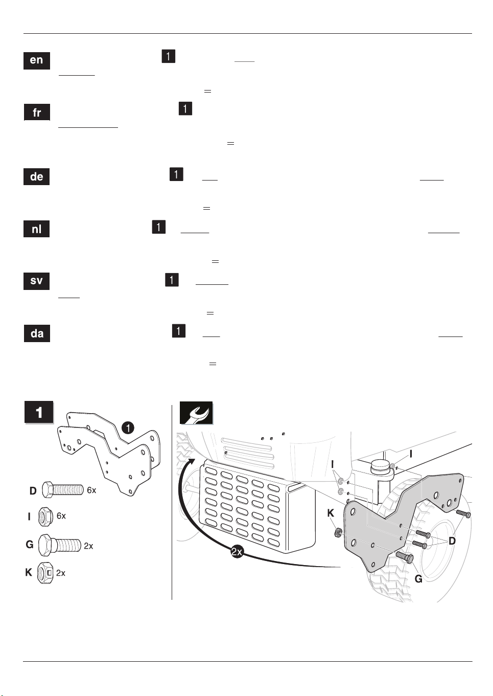
This installation step
is required only
for tractors of the 600 and 700 series
without Fast-Attach System.
Example: Model number 13AA688F678 = here 600 series
Cette étape de montage
ne concerne que les tracteurs de la série 600 et 700
non équipés du système de fixation rapide (Fast-Attach-System).
Exemple : numéro du modèle 13AA6 88F678 = ce 6 indique qu'il s'agit de la
série 600
Dieser Montageschritt
ist nur bei Traktoren der 600er und 700er-Serie ohne
Fast-Attach System erforderlich.
Beispiel: Modellnummer 13AA688F678 = hier 600er-Serie
Deze montagestap
is alleen vereist bij tractoren van de serie 600 en 700 zonder
Fast Attach-Systeem.
Voorbeeld: modelnummer 13AA6
Detta monteringssteg
är endast nödvändigt hos traktorer ur 600 och 700-serien
88F678 = hoort bij serie 600
utan Fast-Attach-System.
Exempel: Modellnummer 13AA688F678 = 600- serien
Dette monteringsskridt
er kun nødvendigt for traktorer i 600 og 700-serien uden
Fast Attach-System.
Eksempel: Modelnummer 13AA688F678 = her 600-serien
4
Page 5

567
Page 6

Page 7

Page 8

20
Page 9

jqa=e~еЗЙдлЦЙлЙддлЕЬ~Сн=гДe
tЙдлЙк=pнк~Й=NOO
QSNQ=j~кЕЬнкЙев
* MT=OQ=OS=MR=RR
MT=OQ=OS=MR=RQ
===
jqa=_ЙеЙдмс=kKsK
mкбел=^дДЙкнд~~е=VS
_JUUTM=fтЙЦЙг
* HHPOJRN=QM=OQ=QN
HHPOJRN=QM=PT=TR
jqa=jзнзкЦЙк®нЙ=dгДe
fеЗмлнкбЙлнк~Й=VУNN
TPMRQ=bблдбеЦЙе=L=cбдл
* M=TN=SN=UR=MR=M
M=TN=SN=UR=MR=TM
jqa=mçä~åÇ=ëéK=ò=çKçK
riK=lЦкзЗебЕт~=N
UQJORO=lкдЙ
* MRU=RT=OM=TMN
MRU=RT=OM=SVV
jqa=aÉåã~êâ=^ép
jЙллбеЦоЙа=PM=^
UVMM=o~еЗЙкл
* UT=NN=VN=MM
UT=NN=VS=MM
jqa=fенЙке~нбзе~д=cк~еЕЙ
_KmK=QRP=p~бенJbнбЙееЙ=Зм=oзмок~у
TSUMS=`ЙЗЙс
* MO=PO=VN=VQ=PO
MO=PO=VN=VQ=PS
bKmK_~êêìë=iqa
i~мензе=oз~З
luS=Mro=_бЕЙлнЙкI=lсСзкЗлЬбкЙ
* M=NU=SV=PS=PS=PS
M=NU=SV=PS=PS=OM
jqa=eìåÖ•êá~=hÑí
aµòë~=dóÕêÖó=Ñн=N
UOQU=kЙгЙло•гзл
* MS=UU=RN=RR=MM
MS=UU=RM=RR=OM
jqa=qк®ЗЦ™кЗлг~лвбеЙк
p®íìå~î®ÖÉå=P
RONQN=c~äâÕéáåÖ
* M=RN=RN=TN=MM
M=RN=RT=NN=QN=Q
jqa=pЕЬпЙбт=^d
^ддгЙеЗлнк~Й=NQ
RSNO=sбддгЙкЦЙе
* MR=SS=NU=QS=MM
MR=SS=NU=QS=MV
MTD Products Aktiengesellschaft
Industriestraße 23
D-66129 Saarbrücken
Germany
* ++ 49-6 80 57 90 • ++ 49-6 80 57 94 42
© 2007 MTD Products AG
Page 10

English 2ZQHUV*XLGHÒ6QRZEODGHIRUODZQWUDFWRUV
8
Snow blade for lawn
tractors
Unpacking/attaching
the snow blade
6MWOSJMRNYV]
Before attaching the device:
– Switch off the lawn tractor engine.
– Remove the ignition key
– Wait until all moving parts have
come to a standstill, allow the
engine to cool down.
– Apply the parking brake
– Remove the spark-plug connector
from the lawn tractor to prevent
the engine from being inadver-
tently started.
6MWOSJFYVRW
Before attaching the device, allow
the exhaust pipe to cool.
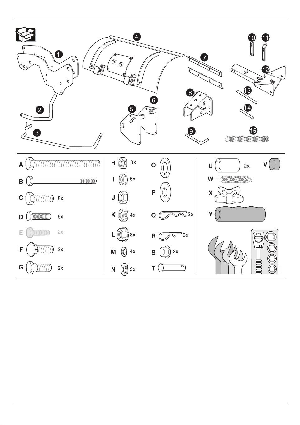
Unpacking the snow blade
When unpacking the snow blade,
check the contents of the pakkaging.
If there are any missing or damaged
parts, please consult your dealer.
Preparing the lawn tractor
Switch off the mower deck drive.
Remove the attached components
(e.g. front bumper) from the front of
the lawn tractor.
Note:
To prevent damage to the mower
deck (if unintentionally switched on
or due to corrosion), we recommend
removing the mower deck prior to
using the lawn tractor in winter. If
required, consult an MTD service
centre.
Attaching the snow blade
Attach the device as illustrated at the
beginning of these instructions.
Safe operating practices
Follow safety and operating
instructions
Before using the device for the first
time, please read these instructions
carefully. Follow all safety instructions while operating the device.
Make sure that
– you are familiar with all the instruc-
tions,
– all users of the device have been
informed about the instructions
and have understood them.
Also follow the safety and operating
instructions in the manual for the
lawn tractor to which this device is
attached.
Safety instructions
Before performing any work
on this device
Before performing any work on this
device:
– Switch off the lawn tractor engine.
– Remove the ignition key
– Wait until all moving parts have
come to a standstill, allow the
engine to cool down.
– Apply the parking brake
– Remove the spark-plug connector
from the lawn tractor to prevent
the engine from being inadver-
tently started.
While using the device
Risk of injury – keep persons, especially children and pets, out of the
way of the device.
Using the device
correctly
This device is intended to be used
– as a snow blade for lawn tractors,
– in accordance with the descrip-
tions and safety instructions in this
operating manual.
Any other use is considered as
improper. The user is liable for any
injuries to third parties and/or
damage to their property.
The manufacturer is not liable for any
damage and/or injury resulting from
unauthorised changes to the device.
Operation
Note: Directional references on the
device (e.g. on the left, right) are
always considered from the driver’s
seat in the working direction of the
device.
Illustrations at the end
of the manual.
Adjusting the snow
clearance direction
Fig. 1
To improve snow clearance, the
snow blade can be placed in either
of two angular positions in addition
to the standard position:
Clearing the snow to the left or right:
– Pull back the lever.
– Rotate the snow blade to the left
or right until the lever locks into
position in the corresponding
notch.
– Check that the lever has locked
into position correctly.
!
!
Page 11

2ZQHUV*XLGHÒ6QRZEODGHIRUODZQWUDFWRUV English
9
Driving with the attached
snow blade without
clearing snow
Fig. 2
– Raise the snow blade and lock
in position by pulling back the
control lever.
Overcoming obstacles
'EYXMSR
Crossing high kerbs or other
obstacles may damage the device.
Low obstacles, e.g. manhole covers,
can be crossed without difficulty.
A compression spring with shock
absorber action allows the snow
blade to spring back and overcome
obstacles.
To overcome larger obstacles, raise
the snow blade by pulling back the
control lever.
Adjusting the compression
spring pretension
Fig. 3
Standard setting
– Distance between the nut (1) and
tip of the threaded rod (2) approx.
2.5 cm.
Hard suspension
– Loosen nut (1) and retighten wing
nut (3).
Soft suspension
– Rotate the nuts in an anti-
clockwise direction.
Adjusting the working
height
Fig. 4
Depending on the ground, the
working height can be adjusted via
the runners. If the ground is uneven,
e.g. due to a gravel surface or raised
manhole covers, a greater working
height is required.
– Loosen the locknuts.
– Move the runners, tighten the
locknuts.
Attaching or removing the
snow blade
Before attaching or removing the
snow blade:
– Switch off the lawn tractor engine.
– Remove the ignition key
– Wait until all moving parts have
come to a standstill, allow the
engine to cool down.
– Apply the parking brake
– Remove the spark-plug connector
from the lawn tractor to prevent
the engine from being inadver-
tently started.
Attaching the snow blade
Fig. 5 a
– Push the snow blade onto the
retention bolts.
– Allow locking hooks on both sides
to lock into position.
– Check that the locking hooks
have locked into position cor-
rectly.
Removing the snow blade
Fig. 5 b
– Pull out the locking hooks
(both sides) and swivel down.
– Pull the complete snow blade off
the retention bolts.
Tips on working with the
snow blade
To increase clearance and safety,
we recommend attaching snow
chains.
To prevent the quantity of snow from
becoming too large, clear in more
than one direction.
Clear large areas by working outwards and pushing snow uniformly
to all sides.
Shutting down the
appliance
For example, at the end of the
season or if the device is not to
be used for more than a month:
– Clean the device.
– To protect all metal parts against
rust, wipe with an oiled rag (resinfree oil) or spray with spray oil.
Maintenance
Maintenance procedures
Before using, always
– check that all threaded connec-
tions are secure; if required,
retighten.
Fig. 6
– Check wearing rail (1) and runners
(2) for wear; if required, replace.
Warranty
In each country, the warranty conditions issued by our company and/or
importer apply.
Defects in the equipment will be rectified by us free of charge during the
warranty period where these are the
results of flaws in the material or in
the manufacture of the equipment.
In case of warranty claims, please
contact your dealer or nearest
branch office.
!
 Loading...