

Page 1

For Discount White Outdoor Parts Call 606-678-9623 or 606-561-4983
Shop Handbook
NOTE: These materials are for use by trained technicians who are experienced in the service and repair of outdoor power
equipment of the kind described in this publication, and are not intended for use by untrained or inexperienced individuals.
These materials are intended to provid e su pp lem ental information to assist the trained technician. Untrained or inexperienced individuals should seek the assistance of an experienced and tr ained professional. Read, understand, a nd follow all
instructions and use common sense when working on power equipment. This includes the contents of the product’s Operators Manual, supplied with the equipment. No liability can be accepted for any inaccuracies or omission in this publication,
although care has been taken to make it as complete a nd accura te as possib le at the time of publica tion. However, due to
the variety of outdoor power equipment and continuing product changes that occur over time, updates will be made to these
instructions from time to time. Therefore, it may be necessary to obtain the latest materials before servicing or repairing a
product. The company reserves the right to make changes at any time to this publication without prior notice and without
incurring an obligation to make such changes to previously published versions. Instructions, photographs and illustrations
used in this publication are for reference use only and may not depict actual model and component parts.
© Copyright 2006 MTD Products Inc. All Rights Reserved
MTD Products Inc - Product Training and Education Department
www.mymowerparts.com
830-860 Series mowers
FORM NUMBER - 769-03727
12/2007
Page 2

For Discount White Outdoor Parts Call 606-678-9623 or 606-561-4983
www.mymowerparts.com
Page 3

For Discount White Outdoor Parts Call 606-678-9623 or 606-561-4983
Chapter 1: Introduction ......................................................................................................1
830 series ............................................................................................................................ 1
860 series ............................................................................................................................2
Chapter 2: Front wheels and axle ...................................................................................... 3
Front wheels ........................................................................................................................3
Front axle............................................................................................................................ 3
Chapter 3: Cutting blade .................................................................................................... 5
Chapter 4: Drive belt and baffles .......................................................................................7
Chapter 5: Speed control system ......................................................................................10
How the speed control works............................................................................................ 10
Speed control cable and lever.......................................................................................... 11
Clutch cable replacement ..................................................................................................14
Chapter 6: Transmission and rear wheels .......................................................................16
Transmission replacement ................................................................................................ 16
Low wheel mower ............................................................................................................ 16
Large-wheel mowers......................................................................................................... 21
www.mymowerparts.com
Page 4

For Discount White Outdoor Parts Call 606-678-9623 or 606-561-4983
830-860 SERIES SELF-PROPELLED MOWERS
CHAPTER 1: INTRODUCTION
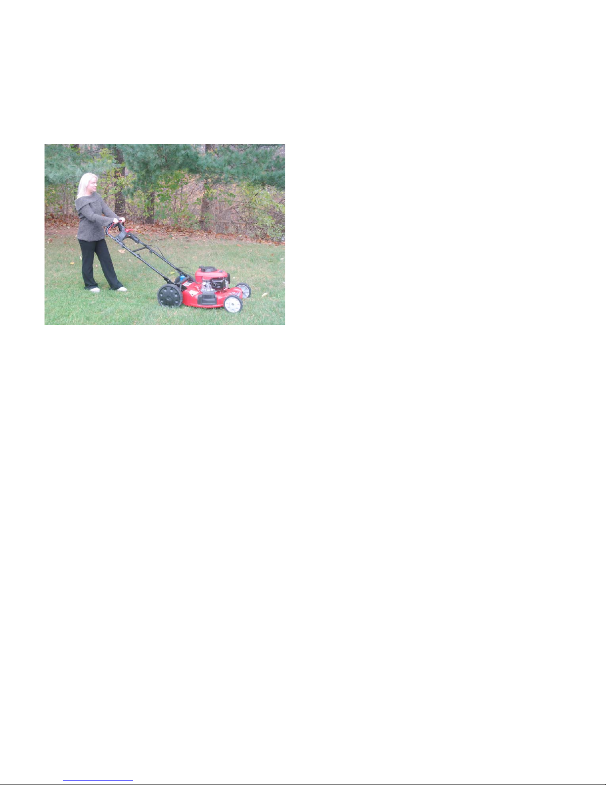
The 830 and 860 Series lawn mowers are rear-wheel
drive self-propelled mowers with a unique variable
ground speed feature. They are both capa ble of mulching, bagging or side-discharging grass clippings . Both
mowers have a 21” (53cm) cutting swath.
NOTE: This manual was prepared using preproduction mowers. The information contained
in the manual is true at the time of writing, but
the equipment may change without notice .
NOTE: This manual is intended to help professional technicians become acquainted with
newly introduced equipment, so that they can do
their jobs faster, better, and more easily.
If the user of this manual lacks tools or expertise
necessary to safely perform the tasks described,
they should seek the assistance of a trained professional.
NOTE: As should be standard operating procedure for any professional, test the operation of
the mower after any repair work, before returning it to service.
CAUTION: Disconnect and ground the s park
plug wire whenever there is a risk of injury from
rotating parts. Working on the cutting blade or
drive system are two examples of situations that
could place a technician at risk.
CAUTION: Take measures to avoid the creation
of a fire hazard when working around equipment
that would normal contain fuel:
830 series
The 830 series is identified by and eleven digit model
number, e.g.: 12A-83X
“12” indicates that it is a self-propelled mower,
“A” identifies the first generation of the model series.
“A” may be followed by an engine identifier.
The “X”s will be style and retailer identifiers. Engines
from different manufacturers may be used on different
models. The models depicted here are in Troy- B ilt livery, but similar models may be produced in different
lines and for different retailers. See Figure 1.1.
-XXX.
Figure 1.1
• Drain and store fuel in safe containers.
• Clean any fuel spills immediately.
• Avoid exposing fuel to heat sources or open
flame.
NOTE: Replace any worn or damaged fasteners. If a lock washer or bellville washer has lost
its tension, replace it. If the locking feature of a
self-locking nut has worn, replace the nut, or
install it using releasable thread-locking com-
pound such as Loctite
TM
242 (blue).
www.mymowerparts.com
1
Page 5
For Discount White Outdoor Parts Call 606-678-9623 or 606-561-4983
830-860 SERIES SELF-PROPELLED MOWERS
860 series
The 860 series is very similar to the 830 Series except
for large rear wheels and some engineering dif ferences
that are necessary to accommodate the large rear
wheels. See Figure 1.2.
Figure 1.2
Differences include:
• Lower handlebars are longer on the 860 Series
than they are on the 830 Series.
• The single-point height adjust lever is on the lefthand side on the 830 Series, but it is on the
rig ht-h and-side on the 860 Series.
• The handlebar brackets are different between
the two models.
• The 860 Series has different final-drive gears,
including an idler gear between the transmission
axle and the ring gear in the rear wheel.
www.mymowerparts.com
2
Page 6
For Discount White Outdoor Parts Call 606-678-9623 or 606-561-4983
830-860 SERIES SELF-PROPELLED MOWERS
CHAPTER 2: FRONT WHEELS AND AXLE
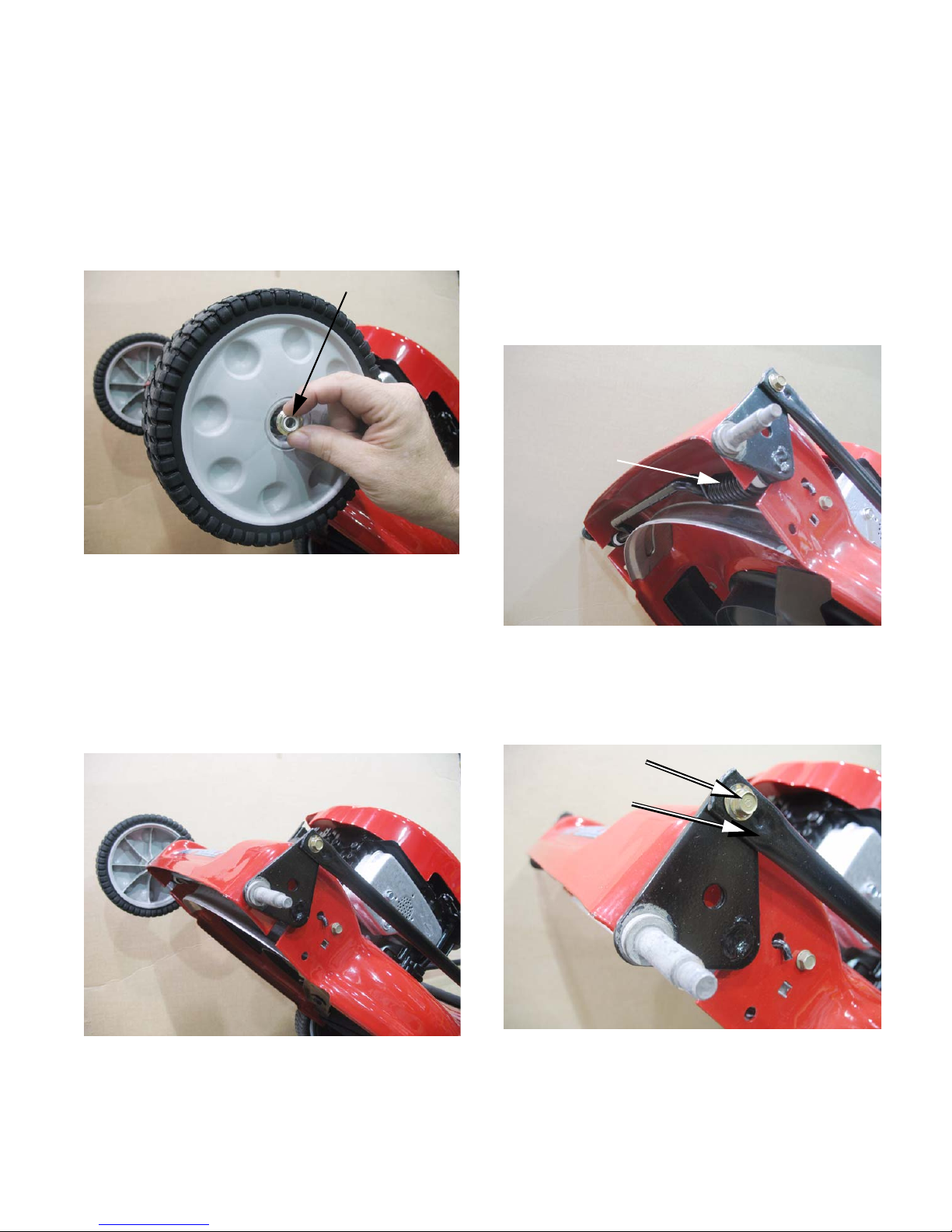
Front wheels
The front wheels fit over the ends of the axle, and are
held to the axle by nuts. See Figure 2.1.
nut
Figure 2.1
To remove the front wheels:
1. Loosen the wheel nuts using a 9/16” wrench.
2. Tilt the mower up so that the weight of the
mower is not resting on the front wheels.
3. Remove the nuts, and pull the front wheels off of
the mower. See Figure 2.2.
Front axle
To remove the front axle:
1. Remove the front wheels.
2. Set the height adjuster lever to the highest position, relieving the load on the lift-assist torsion
spring on the front axle . See Figure 2.3.
Torsion spring
Figure 2.3
3. Remove the shoulder screw that holds the
height adjuster connecting link to the front axle.
Use a 3/8” wrench. See Figure 2.4.
Wheel removed
Figure 2.2
4. When reinstalling the front wheels, tighten the
nuts to a torque of 12 ft.-lb.(166.3 N-m).
Shoulder screw
Height adjuster
connecting link
Figure 2.4
CAUTION: The torsion spring on the front axle
will be under tension, even in the highest cutting
position.
3
www.mymowerparts.com
Page 7
For Discount White Outdoor Parts Call 606-678-9623 or 606-561-4983
830-860 SERIES SELF-PROPELLED MOWERS
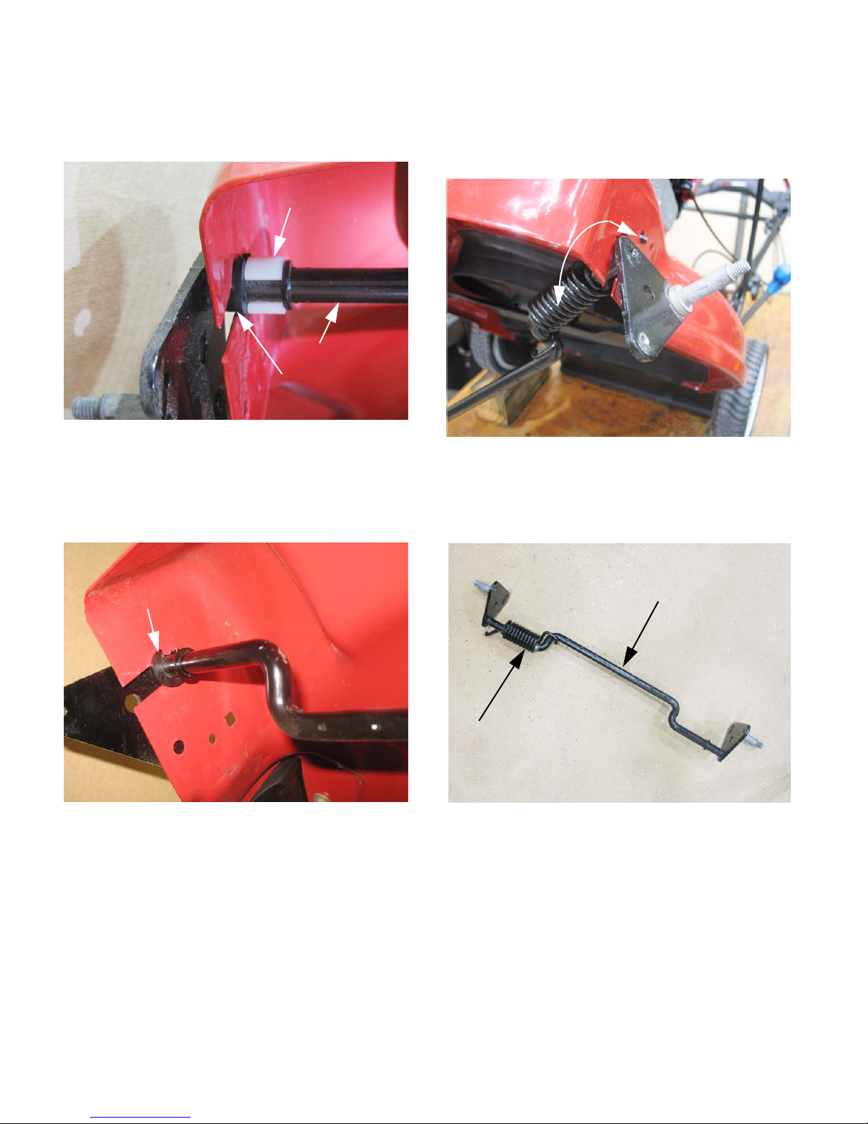
4. Just inside of the deck shell, near each end of
the axle is a white plastic “C” clip. Remove both
“C” clips. See Figure 2.5.
C clip
Front axle
Flanged hex bushing
Figure 2.5
5. The “C” clips hold flanged hex bushings into keyhole slots in the deck shell. Slide the hex bushings in to release them from the deck shell.
See Figure 2.6.
6. As the flanged hex bushings are released from
the deck shell, the axle will come free of the
shell. Maneuver the front axle to unhook the to rsion spring from the deck shell. See Figure 2.7.
Torsion
spring
Figure 2.7
7. The torsion spring is captive on the front axle. If
either is damaged, both must be replaced.
See Figure 2.8.
Flanged hex bushing
Figure 2.6
Front axle weldment
Torsion spring
Figure 2.8
8. Reinstall the front axle by reversing the steps
used to remove it.
• Replace the “C” clips if they have lost their tension.
• Replace the flanged hex bushings if they are
worn.
• Do not trim the flanged hex bushings to ease
installation. They should be tight.
www.mymowerparts.com
4
Page 8
For Discount White Outdoor Parts Call 606-678-9623 or 606-561-4983
830-860 SERIES SELF-PROPELLED MOWERS
CHAPTER 3: CUTTING BLADE
To remove the cutting blade:
1. Disconnect and ground the spark plug wire.
2. If the level of gasoline in the fuel tank is great
enough that it will spill if the mower is tipped,
remove the fuel filler cap, place a plastic bag
over the neck of the fuel tank, and reinstall the
cap.
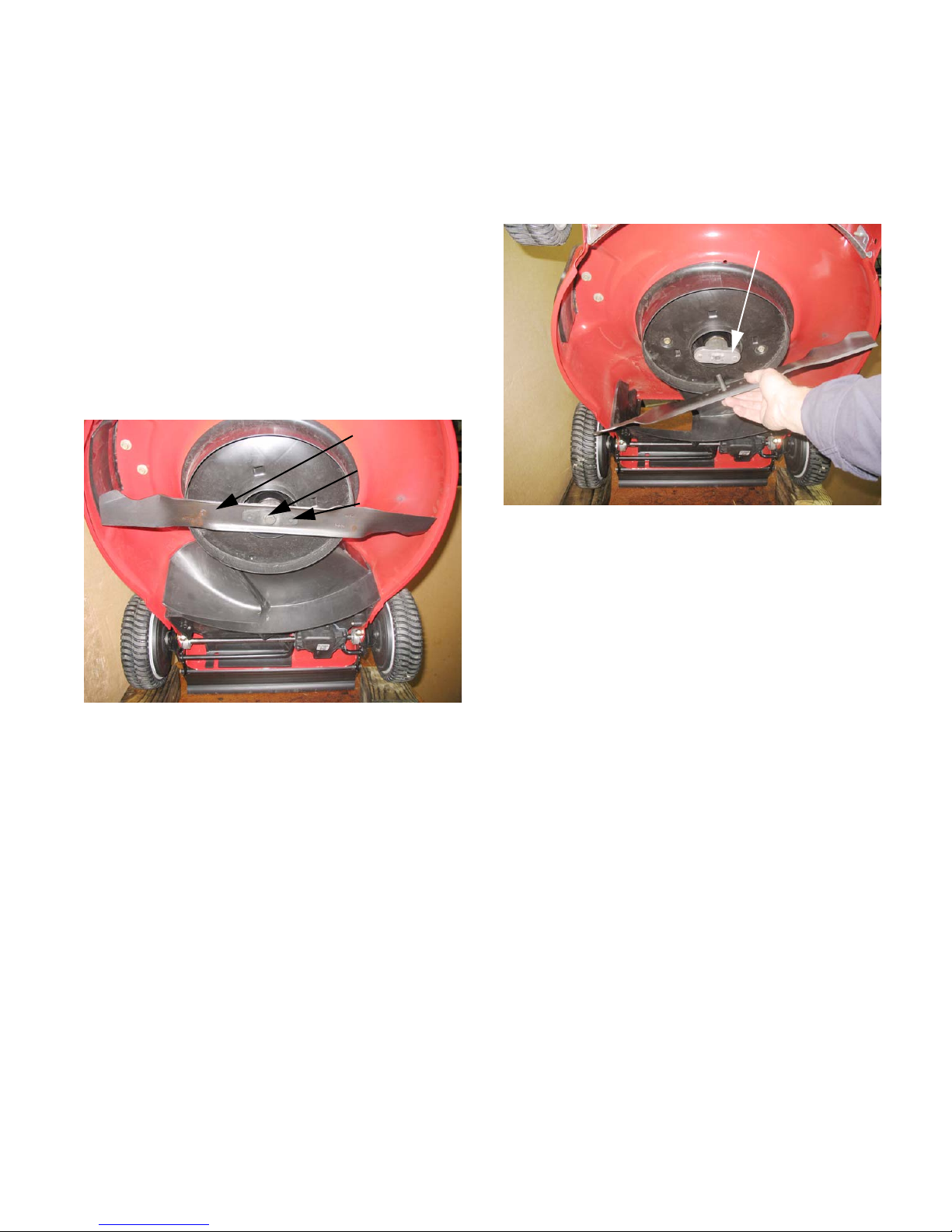
3. Tip the mower with the muffler side down, or tilt
the mower back on a work bench, with the front
wheels up. See Figure 3.1.
Blade
Bolt
Belville spring
6. Lift away the blade. See Figure 3.2.
Blade adaptor
Figure 3.2
7. Inspect the blade. If it is bent or worn beyond
proper sharpening, replace it with a new blade.
8. Sharpen and balance the blade if it is not badly
worn.
Figure 3.1
4. Block the blade form rotating using a block of
wood or a blade holder tool.
5. Remove the blade bolt and diamond-shaped
bellville blade spring using a 5/8” wrench.
NOTE: The 830 and 860 Series mowers have a
3-in-1 blade. The outer part of the leading edge
cuts the grass. A wing behind it lift s the grass for
the next blade and propels clippings toward the
bag or side discharge chute if the path to either
is open. A stepped-up cutting edge just in-board
of the outer cutting edge mulches clippings as
they fall, if the side discharge chute is closed
and the mulch plug is in place.
www.mymowerparts.com
5
Page 9

For Discount White Outdoor Parts Call 606-678-9623 or 606-561-4983
830-860 SERIES SELF-PROPELLED MOWERS
9. Check the blade adaptor for damage. There is a
wave washer on the crankshaft, directly above
the wave washer. See Figure 3.3.
Crankshaft
Wave washer
Blade adaptor
Figure 3.3
10. Install the blade with wave washer, blade adaptor, and bellville spring washer properly positioned. Tighten the blade bolt to a torque of 3850 ft.-lb. (51-68 N-m).
www.mymowerparts.com
6
Page 10

For Discount White Outdoor Parts Call 606-678-9623 or 606-561-4983
830-860 SERIES SELF-PROPELLED MOWERS
CHAPTER 4: DRIVE BELT AND BAFFLES
To remove the drive belt:
1. First remove the mulch plug. See Figure 4.1.
Mulch plug
Figure 4.1
2. Remove the blade as described in Chapter 2:
Cutting blade..
3. Remove the baffle extension cover using a 3/8”
wrench. See Figure 4.2.
4. Remove the rear baffle:
4a. Remove the two screws that hold the rear of
the baffle to the mower deck. The screws
are located just in front of the handlebar
brackets, and can be removed using a 3/
8” wrench. There is one on the left and
one on the right. See Figure 4.3.
Baffle screw
Figure 4.3
Figure 4.2
Baffle
extension
4b. Remove the two nuts and bolts that hold the
right handlebar bracket to the mower deck
using a pair of 1/2” wrenches. They do
not hold the baffle in place, but they get in
the way of its removal. See Figure 4.4.
Handlebar
bracket
Bolts
Baffle (inset)
Nuts on bolts that impede the
removal of the baffle
Figure 4.4
www.mymowerparts.com
7
Page 11

For Discount White Outdoor Parts Call 606-678-9623 or 606-561-4983
830-860 SERIES SELF-PROPELLED MOWERS
5. Remove the single screw that holds the front of
the baffle to the mower deck, using a 3/8”
wrench.
6. Pull the front edge of the baffle down, and
remove it from the mower. See Figure 4.5.
Figure 4.5
7. Crankshaft pulley cover removal:
8. Remove the belt by:
8a. Pull the belt down off of the crankshaft.
See Figure 4.7.
Figure 4.7
8b. Slip the belt out of the transmission pulley,
and remove it. See Figure 4.8.
7a. Remove the three screws that hold the
crankshaft pulley cover to the mower deck
using a 3/8” wrench.
7b. Pull the crankshaft pulley cover and the
lower sheave of the crankshaft pulley
down, freeing the belt from the crankshaft
pulley. See Figure 4.6.
Belt
Upper sheave
Lower sheave
Figure 4.6
Figure 4.8
www.mymowerparts.com
8
Page 12

For Discount White Outdoor Parts Call 606-678-9623 or 606-561-4983
830-860 SERIES SELF-PROPELLED MOWERS
9. Check the crankshaft pulley:
9a. The splines in both sheaves of the crank-
shaft pulley should be clean and smooth,
so that they slide together easily.
See Figure 4.9.
Upper sheave
of crankshaft
pulley
Splines
Figure 4.9
NOTE: The splines should not need lubrication.
If any lubrication is applied, use a dry PTFE
TM
(Teflon
sparing quantities.
9b. The upper sheave of the crankshaft pulley
) or graphite based lubricant in very
should slide off of the crankshaft. There is
a spacer above the sheave. The length of
the spacer will vary with the engine
model. If one end of the I.D. of the spacer
is rounded or beveled, that is the end that
goes up, toward the engine.
See Figure 4.10.
10. Replace the belt:
10a. Reverse the removal process.
10b. It will help to spread the sheaves on the
transmission pulley, and tug the belt deep
into the sheaves of the transmission pulley. This will leave the maximum amount
of slack in the belt, so it is easier to slip
around the crankshaft pulley.
See Figure 4.11.
Carefully spread the sheaves of the variable
speed pulley on the transmission to ease
belt installation.
Figure 4.11
NOTE: Use only the Original Equipment belt.
Other belts of slightly different size or profile will
effect the grounds speed of the mower. Belts of
different material may wear-out faster.
Crankshaft spacer
(varies with
engine model)
Figure 4.10
www.mymowerparts.com
9
Page 13

For Discount White Outdoor Parts Call 606-678-9623 or 606-561-4983
830-860 SERIES SELF-PROPELLED MOWERS
CHAPTER 5: SPEED CONTROL SYSTEM
How the speed control works
1. The red lever on the control panel applies tension to a cable. See Figure 5.1.
Red lever = speed control
Figure 5.1
2. The cable runs down into the crankshaft pulley
cover, where it pulls on an arm that rotates a
cam. See Figure 5.2.
3. The cam has a series of ramps that work against
ramps in the crankshaft pulley cover, forcing the
two sheaves of the crankshaft pulley together.
4. When the crankshaft pulley sheaves squeeze
together, the force the contact patch of the drive
belt further out on the pulley. The outer part of
the pulley travels at a higher linear speed than
the part closer to the crankshaft, shifting the
drive ratio in the direction of greater speed.
5. The belt does not stretch any significant amount.
When the engine end pulley effectively grows,
the tension on the belt increases.
6. The sheaves on the transmission pulley are
spring-loaded to react to the added belt tension.
See Figure 5.3.
Power ratio to wheels Speed ratio to wheels
Ramps
Figure 5.2
www.mymowerparts.com
Figure 5.3
Bottom end of
speed control
cable
10
Page 14

For Discount White Outdoor Parts Call 606-678-9623 or 606-561-4983
830-860 SERIES SELF-PROPELLED MOWERS
7. The driven pulley (transmission) reaction is
opposite of the driving (engine) pulley. As a
given linear belt speed is applied to an effectively smaller pulley, the drive ratio shifts in the
direction of increased speed. See Figure 5.4.
Power ratio to wheels Speed ratio to wheels
Transmission
pulley
Engine pulley
Figure 5.4
Speed control cable and lever
1. Remove the crankshaft pulley cover, as
described in the “DRIVE BELT” section of this
manual.
2. Un-hook the spring from the arm on the speed
control cam. See Figure 5.5.
Crankshaft pulley cover
Speed control
cable spring
Speed control cam
Figure 5.5
3. Release the barbed fitting on the end of the
cable housing from the clutch housing. A 9mm
open-end wrench or a Ford fuel line tool can be
used to release the barbs. See Figure 5.6.
Squeeze barbs
to release
Figure 5.6
www.mymowerparts.com
11
Page 15

For Discount White Outdoor Parts Call 606-678-9623 or 606-561-4983
830-860 SERIES SELF-PROPELLED MOWERS
4. Draw the cable and spring up through the opening in the deck that the cables pass through.
See Figure 5.7.
Pull cable
Figure 5.7
5. Remove the three screws holding the cover to
the bottom of the control panel using a 1/4”
wrench or driver. Pull-down the cover to
remove it. See Figure 5.8.
Screws
6. Beneath the control panel on the handlebar,
remove the cable clamp screw that holds the
speed control cable in place. Use a 5/16”
wrench or driver. See Figure 5.9.
Clamp screw
Figure 5.9
7. Pull the cable housing free of the control panel.
The stop at the end of the cable housing is usually placed in the notch that is second-nearest
the control lever assembly. See Figure 5.10.
Figure 5.8
Cover
Speed control
Second
cable housing
notch
Cable core
Figure 5.10
NOTE: Moving the cable to a notch that is closer
to the control lever will shift the range of available ground speeds in a slower direction.
Moving the cable to a notch that is further from
the control lever will shift the range of available
ground speeds in the faster direction.
www.mymowerparts.com
12
Page 16

For Discount White Outdoor Parts Call 606-678-9623 or 606-561-4983
830-860 SERIES SELF-PROPELLED MOWERS
8. From this point, the cable-end can be maneuvered out of the control lever assembly, and the
cable can be removed completely.
See Figure 5.11.
Detent spring
Figure 5.11
9. Install the replacement cable by reversing the
removal process.
10. Speed Control lever:
10c. Separate the control lever from the cable
quadrant by removing the screw that connects them. Use a 5/16” wrench or driver.
See Figure 5.13.
Cable quadrant
Figure 5.13
10d. Pay attention to the orientation of the lever
to the control panel and the quadrant during reassembly. See Figure 5.14.
10a. Disconnect the top end of the speed con-
trol cable, as described in the “Speed
Control Cable” section of this chapter.
10b. Remove the detent spring:
See Figure 5.12.
Detent spring
Figure 5.12
Cable quadrant
Wide boss fits into
wide notch
Speed control lever
Figure 5.14
10e. Reassemble the control panel by reversing
the order of disassembly.
NOTE: Some technicians find it easier too instal
the detente spring before installing the lever and
quadrant.
www.mymowerparts.com
13
Page 17

For Discount White Outdoor Parts Call 606-678-9623 or 606-561-4983
830-860 SERIES SELF-PROPELLED MOWERS
Clutch cable replacement
1. Preparation:
1a. Remove the baffle as described in Chap-
ter 4: Drive belt and baffles.
See Figure 5.15.
Blade
Baffle extension
Baffle
Removed
Figure 5.15
1b. Disconnect either end of the speed control
cable as described in the “SPEED CONTROL CABLE AND LEVER” section of
this chapter, and pull it through the opening in the deck.
NOTE: The spring on the end of the clutch cable
is large enough that it is extremely difficult to pull
through the opening in the deck with the speed
control cable in place.
3. Squeeze the barbs on the cable housing to
release it from the bracket on the transmission.
A 9mm open-end wrench or a Ford fuel line
removal tool may be handy for this task.
See Figure 5.17.
Bottom end of
clutch cable housing
Bracket
Figure 5.17
4. Once the cable housing is released from the
bracket, the spring on the end of the cable core
can be un-hooked from the clutch arm on the
transmission. See Figure 5.18.
Spring
2. A barbed fitting and a spring connect the bottom
end of the clutch cable to the transmission.
See Figure 5.16.
Barbed fitting
Figure 5.16
Clutch arm
Figure 5.18
14
www.mymowerparts.com
Page 18

For Discount White Outdoor Parts Call 606-678-9623 or 606-561-4983
830-860 SERIES SELF-PROPELLED MOWERS
5. Pull the cable and spring through the opening in
the deck. See Figure 5.19.
Pull clutch cable up
Figure 5.19
6. Remove the push-barb fasteners that hold the
control panel to the upper handlebar.
See Figure 5.20.
7. Pry the cable bracket loose from the upper handlebar. See Figure 5.21.
Cable
bracket
Figure 5.21
8. With the cable slack, the Z-fitting at the top end
of the cable core can be un-hooked from the
clutch bale. See Figure 5.22.
Push-barb
fastener
Clutch bale
bracket
Figure 5.20
Engine stop cable
Clutch cable
Figure 5.22
NOTE: Depending on parts availability, the cable
may have to be replaced in tandem with the
engine stop cable.
9. Install the replacement cable by reversing the
removal process.
www.mymowerparts.com
15
Page 19

For Discount White Outdoor Parts Call 606-678-9623 or 606-561-4983
830-860 SERIES SELF-PROPELLED MOWERS
CHAPTER 6: TRANSMISSION AND REAR WHEELS
Transmission replacement
NOTE: The internal p arts of the transmission a re
not serviceable.
• If the mower suffers a drive failure that cannot b e
attributed to the belt, control cables, or variable
speed pulleys, replace the transmission.
• If the transmission is visibly damaged (broken),
replace the transmission.
Low wheel mower
1. Preparation:
1a. Remove the baffle as described in Chapter
4: Drive belt and baffles. See Figure 6.1.
Blade
Baffle extension
1c. Support the mower by the back of the deck,
in such a way that the rear wheels can be
removed. See Figure 6.2.
Rear wheels
elevated
Figure 6.2
2. Rear wheel and dust cover removal:
2a. Remove the rear wheels using a 1/2”
wrench. See Figure 6.3.
Baffle
Removed
Figure 6.1
1b. Set the cutting height to the highest position.
Steel drive
gear in wheel
Spur gear
Figure 6.3
www.mymowerparts.com
16
Page 20

For Discount White Outdoor Parts Call 606-678-9623 or 606-561-4983
830-860 SERIES SELF-PROPELLED MOWERS
2b. Hold the rear drive axle to prevent it from
rotating, and remove the spur gears using
a T-20 Torx driver. See Figure 6.4.
Clamp drive
axle
Figure 6.4
NOTE: The spur gears are side specific.
• The one that goes on the left side is stamped
with and “L”, and the one that goes on the right
side is stamped with an “R”.
• If they are mounted on the wrong sides, the
wheels will not drive.
NOTE: The screws holding the spur gears to the
drive axle are both conventional right-hand
thread.
2c. Slip the spur gears off of the dr ive axle ends.
See Figure 6.5.
“L”
Figure 6.5
NOTE: The Torx screw that holds the spur gear
to the drive axle should be installed with releasable thread locking compound such as Loctite
242 (blue). Tighten it to a torque of 110-120 in.lb. (12.5-13.6 N-m)
2d. Pull the drive pins out of the cross-holes in
the drive axle. The pins should be lubricated with a small amount of anti-seize
compound on reassembly.
See Figure 6.6.
Axle that supports
the wheel
TM
www.mymowerparts.com
Drive pin
Drive axle
Dust cover
Figure 6.6
2e. Remove the plastic dust cover that fits
between the wheel and the height
adjuster bracket.
17
Page 21

For Discount White Outdoor Parts Call 606-678-9623 or 606-561-4983
830-860 SERIES SELF-PROPELLED MOWERS
3. Releasing the axle bearings
3a. Remove the screws that hold the height
adjustment handle and the height adjuster
connecting link to the left rear height
adjuster. See Figure 6.7.
Height
adjustment
connecting link
Figure 6.7
3b. From inside the cutting deck pry-off the
metal “C” clips that lock the axle bearing
keepers onto the axle bearings (left and
right sides). See Figure 6.8.
3c. Pull the bearing keepers back (inward) to
release the bearings from the height
adjuster brackets. See Figure 6.9.
Handlebar bracket
Axle bearing
Axle bearing keeper
Height
adjustment
handle
Figure 6.9
3d. Drive the axle bearing assemblies outward
to release the axle. See Figure 6.10.
Axle bearing keeper
Figure 6.8
Metal C clip
Figure 6.10
www.mymowerparts.com
18
Page 22

For Discount White Outdoor Parts Call 606-678-9623 or 606-561-4983
830-860 SERIES SELF-PROPELLED MOWERS
4. Transmission removal from deck
4a. With the axle bearing assemblies free of the
deck, the axle will move, but the transmission is still attached to the deck.
See Figure 6.11.
Axle bearing
Figure 6.11
4b. Remove the last screw that holds the trans-
mission to the deck. See Figure 6.12.
Remove transmission
mounting screw
4c. Once the transmission is free of the deck,
the clutch cable can be easily disconnected as described in Chapter 5: Speed
control system. See Figure 6.13.
Figure 6.13
5. Remove the transmission from the wheel carrier
weldment. See Figure 6.14.
Transmission assembly
Drive axle
Wheel axle
Figure 6.12
www.mymowerparts.com
Axle bearing keepers
Wheel carrier weldment
Figure 6.14
5a. Slip the transmission in the direction of the
longer drive axle shaft, disengaging the
shorter drive axle shaft from the wheel
carrier assembly.
5b. Remove the axle bearing keepers from the
axle.
5c. If the axle bearing keepers are in good con-
dition, transfer them to the replacement
transmission.
19
Page 23

For Discount White Outdoor Parts Call 606-678-9623 or 606-561-4983
830-860 SERIES SELF-PROPELLED MOWERS
6. Removing the variable speed pulley from the top
of the transmission:
NOTE: New transmissions may or may not be
supplied with the variable speed pulley attached.
If it is necessary to transfer the pulley to the
replacement transmission, or if repair to the variable speed pulley is necessary , use the following
directions as a guide.
6a. Hold the input shaft from turning using a 7/
16” wrench while unscrewing the shouldered nut using a 1-1/8” wrench. The nut
uses a conventional right-hand thread.
See Figure 6.15.
6c. With the nut and spring removed, the vari-
able speed pulley can be lifted off of the
input shaft. See Figure 6.17.
Figure 6.17
6d. The two sheaves of the variable speed pul-
ley can be separated for cleaning or
inspection. See Figure 6.18.
Figure 6.15
6b. The nut will be under slight spring tension.
Once the nut clears the end of the threads
on the input shaft, remove the nut and the
spring. See Figure 6.16.
Shouldered nut
Spring
Upper sheave
Lower sheave
Figure 6.16
Figure 6.18
NOTE: The splines should not need lubrication.
If any lubrication is applied, use a dry PTFE
TM
(Teflon
sparing quantities.
6e. Reassemble the variable speed pulley by
7. Install the replacement transmission by reversing the steps used to remove the transmission.
) or graphite based lubricant in very
reversing the removal process. Tighten
the shoulder nut to a torque of 110-120
in.-lbs. (12.5-13.6 N-m).
www.mymowerparts.com
20
Page 24

For Discount White Outdoor Parts Call 606-678-9623 or 606-561-4983
830-860 SERIES SELF-PROPELLED MOWERS
Large-wheel mowers
Differences between the 830 Series (small rear
wheels) and the 860 Series (large rear wheels) include:
• An added reduction gear within the rear wh eel to
keep the ground speed within the desired range.
• Different handlebar bracket / height adjuster
bracket assemblies
• Shorter lower handlebars on the 860 series.
• Different height adjuster connector link and handle.
• Height adjuster lever on opposite sides of the
mower: left--hand side for 830, right-hand side
for 860.
• Straight rear wheel carrier assembly (rear axle)
on the 860 Vs. bowed rear wheel carrier assembly on the 830.
• The rear wheels and covers
Rear wheel removal:
1. Pry-out the outer edge of the wheel cover.
See Figure 6.19.
2. The wheel cover is held to the rear wheel by a
relatively small grip-ring, near the hub of the
wheel. See Figure 6.20.
Grip ring
Wheel cover
Figure 6.20
3. Remove the nut and flat washer from the axle
using a 9/16” wrench.
4. Pull the wheel off of the wheel axle.
See Figure 6.21.
Figure 6.19
Dust cover
Idler gear
Wheel axle
Spur gear
Ring gear
Figure 6.21
NOTE: The 830 Series employs a spu r gear that
drives against the outside of the gear attached to
the wheel. In that arrangement, the spur gear
and the wheel rotate in opposite directions.
The 860 Series uses a spur gear to drive an idler
in the opposite direction. The idler then drives
against the inside of a ring gear on the wheel,
driving the wheel in the same direction as the
idler. This arran gement permits use of one
transmission with two reduction ratios.
www.mymowerparts.com
21
Page 25

For Discount White Outdoor Parts Call 606-678-9623 or 606-561-4983
830-860 SERIES SELF-PROPELLED MOWERS
5. The idler gear is easily removed using a 9/16”
wrench. See Figure 6.22.
Idler gear
Wheel
rotation
Spur gear
Figure 6.22
6. The spur gears are directional. See Figure 6.23.
• If a left gear is installed on the right side, it will
not drive the right wheel.
• If a right gear is installed on the left side, it will
not drive the left wheel.
7. The spur gear can be removed with a T-20 Torx
driver. The axle must be clamped, to prevent it
from rotating. See Figure 6.24.
Drive axle clamped
Figure 6.24
8. Beneath the spur gear is a drive pin. Lubricate
the drive pin with a small amount of anti-seize
compound on assembly. See Figure 6.25.
• Each gear is marked with an “L” or an “R”.
“L”
Figure 6.23
Spur gear
Drive pin
Figure 6.25
NOTE: The Torx screw that holds the spur gear
to the drive axle should be installed with releasable thread locking compound such as Loctite
242 (blue).
TM
www.mymowerparts.com
22
Page 26

For Discount White Outdoor Parts Call 606-678-9623 or 606-561-4983
830-860 SERIES SELF-PROPELLED MOWERS
9. With the wheel, spur gear, idler gear, and drive
pin removed, the dust cover can be lifted off of
the axle. See Figure 6.26.
Figure 6.26
9a. With the dust covers removed, the height
adjuster mechanism is exposed.
See Figure 6.27.
10. Transmission removal from the 860 Series is
similar to the 830 Series: See Figure 6.28.
Figure 6.28
10a. Set the cutting height to the highest posi-
tion.
10b. Support the mower, tipped-back, with the
rear wheels elevated.
Figure 6.27
NOTE: The height adjuster bracket pivo ts
around the shouldered stud that carrie s th e idler
gear.
• The idler gear remains at a fixed distance from
the drive axle (spur gear).
• The wheel axle, attached to the height adjuster
bracket, pivots around the stud, keeping the idler
gear also at a fixed distance from the whe el axle.
10c. Remove the baffle as described in Ch apter
4: Drive belt and baffles.
10d. Remove the rear wheels, spur gears, drive
pins, idler gears, and dust covers.
10e. Disconnect the height adjustment connec-
tor link from the left rear height adjuster.
10f. Remove the height adjustment handle from
the right rear height adjuster.
10g. Remove both idler bearing studs.
10h. Remove the wheel carrier weldment.
10i. Release the axle bearings.
10j. Loosen the bolts that hold the right rear
height adjuster to the mowing deck.
10k. Slip the transmission assembly to the right
to remove the axle from the left axle bear-
ing, then move it left to free it of the right
axle bearing.
10l. Disconnect the clutch cable, and remove
the transmission.
www.mymowerparts.com
23
 Loading...