

Page 1
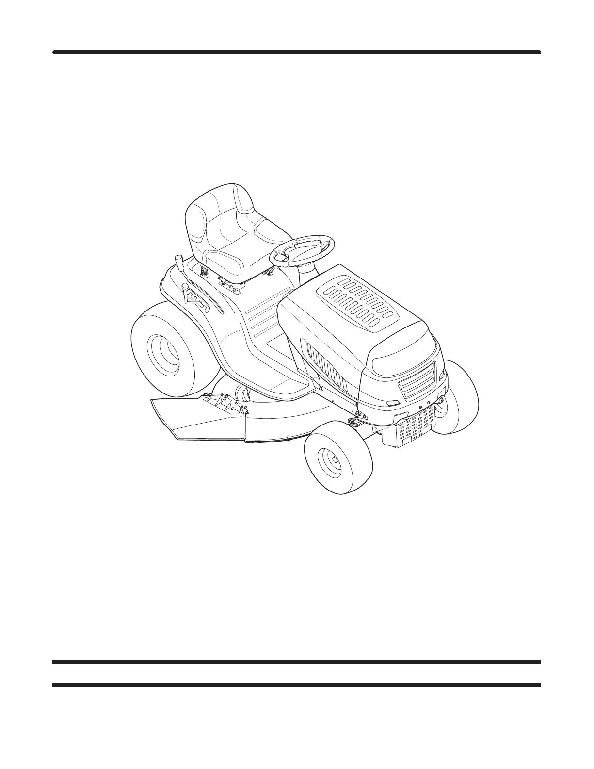
Illustrated Parts Manual
Printed In USA
Hydrostatic Lawn Tractor — Model Series 790
MTD LLC, P.O. BOX 361131 CLEVELAND, OHIO 44136-0019
Form No. 769-07616
(November 17, 2011)
Page 2
To The Owner
Thank you for purchasing an MTD L awn Tr actor. It was carefully
engineered to provide excellent performance when properly
operated and maintained.
All information in this manual is relative to the most recent
product information available at the time of printing. Please be
aware that this Illustrated Part’s Manual may cover a range of
product specifications for various models.
Table of Contents
5 Style Hood ............................................................. 4
K Style (Troy-Bilt) Hood ........................................... 6
Seat and Fender ...................................................... 8
Front End Steering ..................................................10
Transmission ...........................................................12
Frame and PTO Lift ................................................14
Record Product Information
To ease in ordering replacement parts, please locate the model
plate on the equipment and record the information in the
provided area to the right. You can locate the model plate by
looking beneath the seat.
Components listed and/or illustrated in this manual may not be
applicable to all models. We reserve the right to change product
specifications, designs and equipment without notice and
without incurring obligation.
Throughout this manual, all references to right (RH) and left (LH)
are observed from the operating position.
42” Deck ..................................................................16
46” Deck ..................................................................18
Briggs & Stratton Engine Accessories .................. 20
Kohler Courage Engine Accessories ......................21
Wiring Harness Schematic 725-04567F .............. 22
Wiring Harness Schematic 725-04432F .............. 23
Model NuMber
Serial NuMber
Painted Parts
When ordering painted service parts, a four digit color suffix must be added to the part number (e.g. 783-XXXXX-0637).
Please refer to the table below for current color codes:
0637 Black
0709 Dark Green (Bolens, Yard-Man)
0662 Oyster Gray (MTD Gold)
0638 Red (Yard Machines, Huskee, Troy-Bilt, MTD)
0691 Black Jack (MTD Gold, MasterCut)
2
0674 Yellow (Yard-Man)
0650 Metallic Red (White Outdoor)
0629 Silver Flake (MTD Platinum)
04038 Day Orange (Daedong)
04033 Flint Mica (Troy-Bilt XP)
Page 3

This page left intentionally blank.
3
Page 4
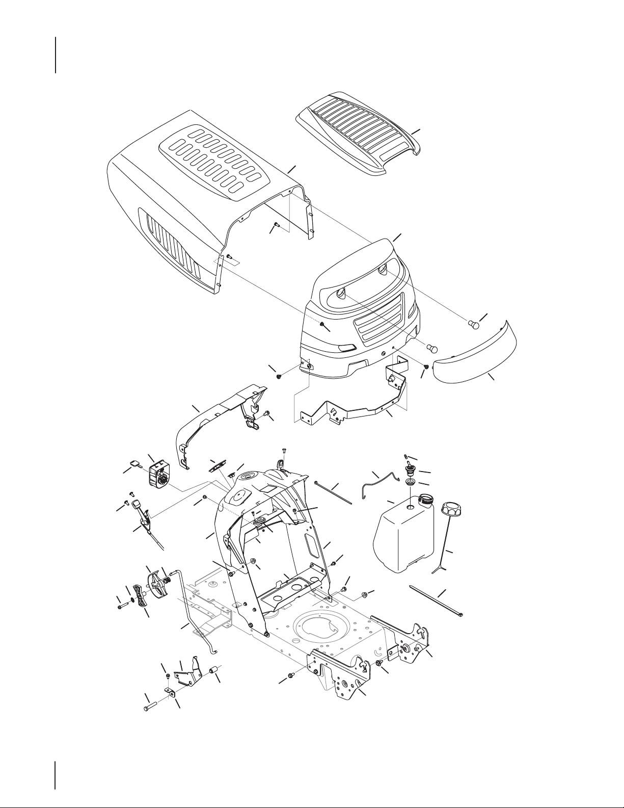
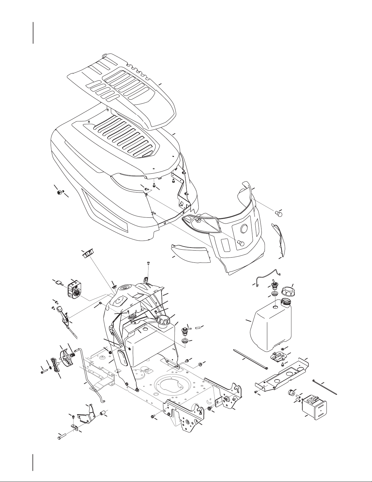
5 Style Hood
48
9
13
36
44
51
14
49
20
1
19
35
17
7
1
8
38
46
47
5
2
3
50
31
6
21
39
37
29
41
22
42
43
21
30
24
23
33
A
28
34
26
16
25
18
4
27
14
15
40
A
10
12
45
32
11
4
Page 5
5 Style Hood
Ref.
No.
1 710-04593 Screw, 5/16-18 x .375
2 710-0751 Hex Screw, 1/4-20 x .620
3 712- 0 4 0 64 Flangelock Nut, 1/4-20
4 710-044 84 Screw, 5/16-18 x .750
5 731-04949A Grill Lens
6 72 5 - 0157 Cable Tie
7 925- 0963 Lamp
8 783-05454 Hood Pivot Bracket
9 783-05683 Hood
10 738- 0 4 091A Shoulder Screw, 5/16-18 x .43 x .29
11 783- 05327B Left Support Pivot Bracket
12 783-05328A Right Support Pivot Bracket
13 710 -04 483 Screw, 1/4-20 x .500
14 710 - 05070 Screw, 1/4-20 x .500
15 710 - 0604A Screw, 5/16-18 x .625
16 712- 0 4063 Flangelock Nut, 5/16-18
17 783-05685 Grill
18 783-07083 Gas Tank Support Bracket
19 910 - 0224 Screw, #10-16 x .500
20 731-05265 Choke Plug
21 710 -1652 Tap Screw, 1/4-20, 0.625
22 710 -3144 Hex Screw, 3/8-16 x 2.0
23 710-3025 Hex Screw, 5/16-18 x .625
24 931-07770 Dash, Upper
25 741-0587 Bearing, .628 ID x 1.36
26 783-06785A Bracket, Steering Support
Part No. Description
931- 08426 Dadh, Upper RMC
Ref.
No.
27 7 8 3 -0 6 811 Dash, Lower
28 750-04465B Flange Spacer, .390 x .671 x 1.095
29 746- 0 4367 Throttle/Choke Cable
30 683-04766 Transmission Speed Latch, RMC
31 683-04448 Battery Assembly Rod
32 726 -0230 Cable Tie
33 747-05398 Speed Control Rod
34 783-06823 Speed Latch Tab
35 951-04304 1.36 Gallon Fuel Tank
36 92 5 -1745A Key
37 736-3006 Lock Washer, 1/4
38 751-12089-28 Hose Vent, 3/16 EPA
39 710 - 0778 Hex Washer Screw, 1/4-20 x 1.50
40 712- 04 0 65 Flangelock Nut, 3/8-16
41 731-07885B Shift Lever
42 731- 07966 Index Control
43 732- 04877 Compr. Spring, .72 OD x .78
44 925-04227B Key Switch Module
45 951-1217 9A Fuel Cap, 2.25”
46 751-12118 Rollover Valve
47 735-04081 Rubber Grommet, 23 x 3.55
48 731-05522A† Hood cover
49 731-05232 Ammeter Plug
50 710-0895 Screw, 1/4-15 x .750
51 731- 05078C† Dash Collar
— 725-04 432G Harness, LT-5, RMC,Dual
Part No. Description
925-04659 Key Switch 3 Position
†If Equipped
NOTE: Tractor features vary by model. NOT all parts listed above and pictured on the previous page are standard equipment.
5
Page 6
K Style (Troy-Bilt) Hood
9
14
49
53
35
17
3
2
39
50
34
16
26
52
48
8
19
30
33
4
56
7
21
31
29
54
B
B
27
38
37
41
28
40
55
20
36
37
13
15
41
40
6
7
38
42
45
1
32
A
5
18
51
27
23
25
22
A
24
B
16
10
1
12
11
44
46
47
43
6
Page 7
K Style (Troy-Bilt) Hood
Ref.
No.
1 710-044 84 Screw 5/16-18 x .750
2 710-05281 Screw, #12-16 x 1.25
3 731- 0640 4 K-Style Bumper
4 710-05108 Screw, 1/4 x .750
5 72 5 - 0157 Cable Tie
6 925- 0963 Miniature lamp 12V socket
7 731- 060 95 Grill Lens - LH
8 910-0224 Screw, #10-16 x .500
9 731-06194B Hood Scoop
10 738- 0 4 091A Shoulder Screw .43 x .29
11 783-05327B Suppport Bracket LH
12 783-05328A Suppport Bracket RH
13 683-04448 Battery Rod
14 683 -04774 Hood
15 631-04272 Grill
16 710-05070 Screw, 1/4-20 x .500
17 710-04 483 Screw 1/4-20 x .500
18 710 -3144 Hex Screw 3/8-16 x 2.00
19 710 -3025 Hex Screw, 5/16-18 x .625
20 712- 0 4065 Flange Lock Nut 3/8-16
21 931-07770 Dash, Upper
22 783-06823 Speed Latch Tab
23 747- 0539 8 Speed Control Rod
24 750 -04465C Flange Spacer .39 x .671 x 1.095
25 683-04766 Transmission Speed Latch
26 746 - 04367 Throttle/Choke Control Cable
27 710-1652 Tap Screw, 1/4-20, 0.625
28 710-060 4A Screw 5/16-18 x .625
29 741-0587 Bearing, .628 ID x 1.36
30 712- 0 4 063 Flange lock Nut 5/16-18
Part No. Description
731-06096 Grill Lens - RH
746- 0 4 4 0 6 Throttle/Choke Cable w/ Knob
Ref.
No.
31 783-06785A Bracket, Steering Support
32 783-07083† Gas Tank Support Bracket
33 7 8 3 -06 811 Dash, Lower NWNDW
34 925- 04227B Key Switch Module
35 925-1745A Key
36 726-0230† Cable Tie
37 951-04295 Fuel Tank, 2 Gallons, EPA
38 951-12179A Fuel Cap
39 92 5 - 04156 Ammeter Monitor Indicator
40 735- 04081 Rubber Grommet
41 751-12118 Rollover Valve
42 936-3008†† Washer, Flat, .344 x .750 x .120
43 951-10589†† Canister, Carbon, 5 Gallon
44 951-10590†† Filter, Vent, Canister
45 951-10610†† Bracket., Adapter, Canister
46 751-10749†† Hose, Fuel, Low Perm., White
47 751-10750†† Hose, Fuel, Low Perm., Yellow
48 731-05265 Choke Plug
49 710 - 0778 Hex Washer Screw, 1/4-20 x 1.50
50 731-07885B Shift Lever
51 731- 0796 6 Index Control
52 732- 04877 Compr. Spring, .685 OD x .63
53 736-3006 Lock Washer, 1/4
54 747- 05373 Fuel Tank Clamp Rod
55 751-120 89-28 Hose Vent, 3/16 EPA
56 710 -04187 Screw, 1/4-15 x 0.50
— 725-04 432G Harness, LT-5, RMC,Dual
— 725-04469 Harness, Jmpr., Amtr.
Part No. Description
783-06656 Dash, Lower
951-04304 Fuel Tank, 1.36 Gallon, CARB
951-12426 Fuel Cap, CARB
† If Equipped
†† Equipped with CARB Fuel Tank
NOTE: Tractor features vary by model. NOT all parts listed above and pictured on the previous page are standard equipment.
7
Page 8
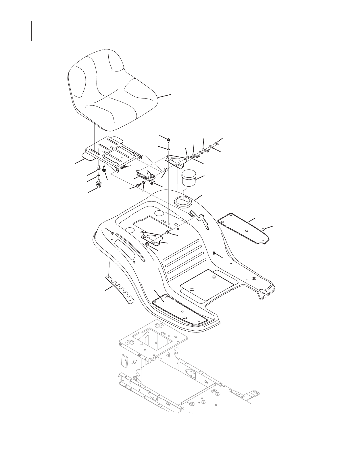
Seat and Fender
25
16
26
2
5
14
9
27
9
1
7
14
11
13
15
12
10
19
10
13
8
23
22
20
21
24
4
6
18
17
3
8
Page 9

Seat and Fender
Ref.
No.
1 710-05070 Screw, 1/4-20 x .500
2 710-044 84 Screw, 5/16-18 x .750
3 710-059 9 Screw Pan Torx Head, 1/4-20 x .500
4 731-04591A Cup Holder
5 736-0607 Loack Washer, 5/16
6 783-04593E Fender
7 783-04843 Lift Adjuster Bracket
8 783-1489 D Seat Mount Bracket
9 710-044 82 Hex Flange, 3/8-16 x .875
10 712- 0 4 0 63 Flangelock Nut, 5/16-18
11 732-118 4 Extension Spring
12 936-0108 Flat Washer, .510x .750 x .033
13 736-0242 Bell Washer, .340 x .872 x .060
14 938-0296 Shoulder Screw, 5/16-18 x .437 x .268
15 783-0209D Lift Seat Bracket
16 783- 04081D Pivot Seat Manual Adjust Bracket
17 726 -3046 Ratchet Clip, .250 x .500
18 735-04047 Foot Pad, LH
19 735-04048 Foot Pad, RH
20 710-0227 Screw, 8-18 x .500
21 726-0279 Insulator Plate
22 925-1303 Outer Seat SPring
23 7 25-1439 Inner Seat Spring
24 726- 0278 Insulator Boss Plate
25 757-04083 Medium Back Seat
26 73 6 - 0148† Lock Washer
27 738- 0 4012 A† Scr., Shldr., .625 x .145 x 3/8-16
Part No. Description
72 0 -0 4 0 61† Knob
723- 04026 Foot Pad, Abrasive, LH
723-04025 Foot Pad, Abrasive, RH
757-04 088 High Back Seat
† If Equipped
NOTE: Tractor features vary by model. NOT all parts listed above and pictured on the previous page are standard equipment.
9
Page 10

Front End Steering
27
13
22
35
3
11
36
14
8
1
17
5
19
20
7
9
28
6
32
8
10
34
15
A
2
18
4
8
27
20
29
24
25
16
23
21
30
12
20
29
26
A
28
33
31
10
Page 11

Front End Steering
Ref.
No.
1 617- 04 094 Front Steering Gear Assembly
2 710-0514 Hex Screw, 3/8-16 x 1.00
3 710-0643 Screw, 5/16-18, 1.00, Gr5, Lock
4 710 -1309 Screw, Mach, 5/16-18, 0.750
5 710 -3180 Screw, 5/16-18, 1.75, Gr5
6 912- 024 0 Nut, Jam, 7/16-20, Gr2
7 912- 0214 Nut, Hex Lock, 3/8-24
8 712- 0 4063 Nut, Flange Lock, 5/16-18, Grf
9 931- 0484A Hub Cap
10 923-0448A Ball Joint, 7/16-20, Lock
11 736-0242 Washer, Bell, .340 x .872 x .060
12 936-0316 Washer, Flat, .78 x 1.59 x .60
13 738- 0 4141 Shoulder Screw, .435 x .3485, 5/16-18
14 738-0919A Steering Shaft, 5/8 Spline x 21.86
15 941-04124 Bearing, Flange, Hex 5/8
16 747-042 99A Tie Rod
17 747- 05385 Steering Link
18 948-0389 Cap, 1.25 x .16
19 748 -0 4 065 Steering, Block
20 74 8 -04068 Spacer, .710 ID x .125 OD x .56
21 731-04693 Push Cap, Cast
Part No. Description
Ref.
No.
22 738 -0 4162A Shoulder Spacer, .884 x .190
23 938 -0 4007A Axle Assmbly LH (38” & 42” Deck)
24 638-04008P Axle Assmbly RH (38” & 42” Deck)
25 919 - 0417 7A Pivot Bar, Cast
26 710-04 484 Screw, 5/16-18, 0.750
27 712- 0 4 0 65 Nut, Flange Lock, 3/8-16, GrF
28 714-04039A Pin, Cotter, 5/32, 1.25
29 914- 0 474 Pin, Cotter, 1/8 x 0.75
30 726 -04035 Push Nut 3/4 Dia.
31 783-05326B Pivot Bar Bracket
32 736-04228A Washer, Flat, .781 x 1.59
33 73 8 - 04128 Scr., Shlder, .500 x 2.380, 3/8-16
34 634-04086-0911 Wheel Ass’y, 15 x 6 x 6 - Grey
35 731-04040 Cap, Steering Wheel (Sprig Logo)
36 631-04028 Steering Wheel, Standard Grip
Part No. Description
938-04014A Axle Assembly, LH (46” Deck)
938 - 04013 Axle Assembly, RH (46” Deck)
634-04639-0911 Wheel Ass’y, Sq. Shldr., 15 x 6 x 6.5
731- 04681 Cap, Steering Wheel (Troy-Bilt)
631- 04560 Steering Wheel Soft Grip
NOTE: Tractor features vary by model. NOT all parts listed above and pictured on the previous page are standard equipment.
11
Page 12

Transmission
23
5
26
24
17
36
58
28
52
45
39
12
30
63
73
2
68
65
74
70
56
42
22
69
17
8
41
16
35
29
22
42
56
13
62
64
71
66
9
6
54
40
18
43
21
48
11
IMPORTANT
FOR a proper working machine,
use Factory Approved Parts.
V- BELTS are designed to engage
and disengage safely. A substitute
(non OEM) V-belt can be dangerous
by not disengaging completely.
19
20
37
10
76
61
60
12
46
15
47
27
21
32
14
18
31
38
18
51
10
53
50
44
49
59
25
34
21
3
72
53
33
75
57
4
7
17
67
55
1
17
Page 13

Transmission
Ref.
No.
1 918-04892A Hydro Transmission
2 647-04200A Hydro Handle Control Assembly
3 647- 04261 Hydro Pedal Assembly
4 710-1266 Hex Screw, 5/16-18 x 3.5
5 710- 0227 Screw, #8-18:0.500
6 710- 03 47 Hex Screw, 3/8-16:1.75
7 910-0224 Screw, #10-16:0.500
8 710- 0448 4 Screw, 5/16-18:.750
9 710- 0514 Hex Screw, 3/8-16:1.00
10 710- 060 4A Screw, 5/16-18:0.625
11 710 -08 09 Screw, 1/4-20:1.250
12 710-1026 Screw, 1/4-20 x 1.75
13 710-30 08 Hex Screw, 5/16-18:.75
14 710 -3103 Screw, 5/16-18 x 2.00
15 711-04448 Ferrule, 5/16-24 X .312 DIA.
16 912- 034 6 Jamlock Nut, 1/2-20
17 712- 0 4063 Flangelock Nut, 5/16-18
18 712 - 040 65 Flangelock Nut, 3/8-16
19 728-04021 Rivet
20 17962 Plate Switch
21 714-04040 Cotter Pin, Bow Tie
22 716 - 010 6A E Rign, .625 DIA
23 720 -0311 Handle Grip
24 725-04249 Hydro Spring Switch
25 726- 0214 Push Cap, 5/8
26 926 -0320 Insulator Plate Nut
27 731- 08237 Sleeve, .765 ID X 2.11 LG
28 731-060 98 Hydro Fan
29 732- 04225 Torsion Spring
30 732- 04229 Extension Spring, .75 DIA. X 6.02
31 732- 0716D Extension Spring, .59 OD X 4.00 LG
32 732-0729 Wire Ring
33 732-04587 Extension Spring, .63 DIA X 4.95 LG
34 735-0239 Foot Pad, 4.0
35 736-04263 Lock Washer, TRANS HYDRO
36 736-0607 Lock Washer, 5/16 EXT TOOTH
37 925- 04039 Switch Interlock
38 736-3010 Flat Washer, .407X.812X.135:HT
39 750- 04456 Spacer, .260 x .372 x 1.420
Part No. Description
918-04925B Hydro Transmission, 18” Tires
Ref.
No.
40 738-04430 Shldr Spacer, 1.375 ID X .380 x 1.54
41 736-0430 Flat Washer, .350 x 1.59 x .062
42 941-02 25 Hex Flange Bearing
43 747- 0560 3 Declutching Rod
44 747-05242 Brake Rod
45 747- 0 42 9 6A Hydro Control Handle
46 747- 05245 Hydro Bypass Rod
47 747- 04 407A Hydro Control Rod
48 750-0566A Spacer, .260 x .375 x 1.030 LG
49 750 -05593 Spacer, .640 ID X .76 OD X 1.60
50 954- 04252 V Belt, 4L SEC X 84.17
51 756-04224 Flat Idler Pulley 2.75 OD
52 756-04308 Input Pulley
53 783-04536B Support Pedal Bracket
54 783- 04570B Idler Arm
55 783-06551 Torque Bracket
56 783-04585A Handle Bracket
57 783-06558 Belt Support Bracket
58 948- 0334 Spacer, T-Axle
59 634-0104-0911 Wheel, 20 x 8 x 8 - Grey
60 710-0627 Hex Screw, 5/16-24 x .750
61 736-0242 Bell Washer, .340 x .872 x .060
62 710 -0106 Hex Screw, 1/4-20 x 1.25
63 936 -0142 Flat Washer, .281 x .500 x .063
64 738-04483 Shoulder Spacer, .375 x .625 x .20
65 741- 042 80 Ball Bearing, .25 x .6875 x .25
66 747- 05598 Hydro Rod, RTN
67 783-06750A Cam Bracket, RTN
68 783- 06756 Pivot Bracket, RTN
69 712- 040 6 4 Nut, Flange Lock, 1/4-20, GrF
70 914-0145 Click Pin, .092 x 1.64 LG
71 710 -3144 Hex Screw, 3/8-16 x 2.00
72 738- 04278 Shoulder Screw, 1/4-20 x 0.50
73 741-3065B Hex Flange Bearing, .628 ID
74 7 5 0 -3119 Spacer, .406 ID x 1.00 OD x .38
75 756-04325 V Pulley 3.06 OD
76 783- 06807 Stop Pedal Plate
— 725-04990 Harness, Jmpr, Hydro
Part No. Description
634-04641-0911 Wheel, 18 x 9.5 x 8
NOTE: Tractor features vary by model. NOT all parts listed above and pictured on the previous page are standard equipment.
13
Page 14

Frame and PTO Lift
51
52
53
18
24
18
34
41
40
33
35
33
31
49
A
36
9
5
46
27
B
1
30
A
19
22
26
B
7
11
C
6
11
10
16
20
23
3
2
13
8
17
15
25
22
26
49
29
20
20
17
28
25
22
3
B
39
4
33
33
1
A
44
11
3
2
11
45
50
50
47
39
14
C
12
3
14
39
21
2
46” Deck Lift
2
42
8
43
48
38
37
32
18
14
Page 15

Frame and PTO Lift
Ref.
No.
1 683- 0 4155A Shaft Assembly Lift 42” Deck
2 712- 04 0 65 Nut, Flange Lock, 3/8-16, GrF
3 714-04040 Pin, Cotter, Bow Tie
4 783-05389A Frame Brace Bracket
5 716-0106A Ring, E-Type, .625 Dia.
6 72 0- 0 311 Grip, Handle, 1/2
7 732-04225 Spring, Torsion 42” Deck
8 738-04130 Screw, Shoulder, .625 x .175, 3/8-16
9 941-0225 Bearing, Hex Flange
10 747- 052 96 Deck Handle, Lift, 42” Deck
11 747-04393 Rod, Lift
12 783-04494C Lift Arm, Deck - RH
13 783 -0 4711C Lift Arm, Deck - LH
14 936-014 0 Washer, Flat, .385 x .62 x .063
15 683 - 04195 Support Bracket Assembly
16 683-04649 Frame Assembly
17 710 - 0134 Carriage Screw, 1/4-20 x .62
18 710-04 484 Screw, 5/16-18, .750
19 725-04439 Solenoid
20 710-30 08 Hex Screw, 5/16-18 x .75
21 712-04 0 63 Flange Lock Nut, 5/16-18
22 712- 04 0 6 4 Nut, Flange Lock, 1/4-20, GrF
23 912- 042 9 Hex Lock Nut, 5/16-18
24 732- 04035 Spring, Compr. , 1.28 OD x 3.125
25 736-0173 Flat Washer, .28 x .74 x .063
26 73 8 - 042 37A Shoulder Screw, #10-32 x .500
27 783-04548D Seat Bracket, Frame
Part No. Description
683-04334 Shaft Assembly Lift 46” Deck
Ref.
No.
28 783- 04637 Bracket, Runing Board
29 783-04753 Frame Support Bracket
30 783-04869A Bracket, Battery
31 6 47- 04096A Handle Assembly, PTO
32 710 - 04608 Screw, 7/16-20, 3.25 42” Deck
33 710-0599 Screw, 1/4-20, 0.500
34 914 -0145 Pin, Click, .092 x 1.64
35 720-04049A Grip, Handle, 3/8
36 732-04276A Spring, Extension
37 936- 0171 Washer, Lock, 7/16
38 736-0322 Washer, Flat, .450 x 1.250 x .164
39 938-0380 Bolt, Shldr. .500 x .270 3/8-16
40 741- 0 4119A Bearing, PTO
41 946 -0 417 3D Cable, Deck Engagement
42 750 -0956 Spacer, 1.010 x 1.400 x .825, 42” Deck
43 95 6 -0 4 0 67A Engine Pulley
44 732-04438 Spring, Torsion 46” Deck
45 720-0298 Grip, Handle, 5/8
46 925-1707D Battery, 155 CCA
47 747-04 653 Deck Handle, Lift, 46” Deck
48 747- 04857 Rod, Belt Keeper (42” Deck)
49 725- 04363 Switch, Interlock
50 783-0678C Deck Lift Link
51 683-04448 Battery Hold Down Rod
52 712-0271 Nut, Sems, 1/4-20
53 710-04666 Screw, Carriage, 1/4-20, .75, Gr5
Part No. Description
68 3- 0 4 414 Rod, Belt Keeper (46” Deck)
NOTE: Tractor features vary by model. NOT all parts listed above and pictured on the previous page are standard equipment.
15
Page 16

42” Deck
1
17
14
16
10
16
52
42
36
13
11
40
3
7
29
32
9
16
23
12
2
48
54
53
48
54
16
32
8
37
25
6
27
22
16
4
8
20
15
12
30
35
34
55
9
1
24
44
9
6
47
41
31
19
33
28
33
5
56
18
50
45
28
46
16
43
38
49
26
39
17
21
51
Page 17

42” Deck
Ref. Part Number Description
1. 918- 04822 A Spindle Ass’y, Pulley, 6.3 Dia
2. 683-0254B Bracket Ass’y, Deck, Hanger LH
3. 9 8 3 -0 4 511 Brake Ass’y, Deck, 42/46
4. 983-04525 Brake Ass’y, Deck, 46”
5. 983-04572 Deck Ass’y, Oset, 42 W/ 2 wheel
6. 710-044 84 Screw, Self-tapping, 5/16-18, .750
7. 710-30 05 Hex Screw, 3/8-16, 1.25, Gr5, Std
8. 710-0528 Hex Screw, 5/16-18, 1.25, Gr5, Std
9. 710-0599 Screw, Self-tapping, 1/4-20, 0.500
10. 936-3039 Flat Washer, .406 x 1.500 x .105
11. 710-0642 Screw, Self-tapping, 1/4-20, .750
12. 710 -3144 Hex Screw, 3/8-16, 2.00, Gr5, Std
13. 710 -3178 Bolt, Carriage, 3/8-16, 0.75, Gr1
14. 712 - 0229 Nut, Push, 3/8
15. 712- 04 0 63 Nut, Flange Lock, 5/16-18, Grf
16. 712- 0 4 065 Nut, Flange Lock, 3/8-16, Grf
17. 712- 0 417A Nut, Flange, 5/8-18
18. 712- 0 4243 Nut, Lock, 1/2-13
19. 912 - 0641 Nut, Hex, M16-1.5
20. 714-04043 Bow-Tie Cotter Pin
21. 783-06074 A Chute Bracket
22. 917-04074 Gear, Deck, Adjustment
23. 932- 0384 Spring, Extension, .62 Dia x 6.12
24. 921-04041† Water Nozzle Adapter
25. 732-04840 Spring, Torsion, .992 ID X 1.17 OD
26. 73 4 -04155† Wheel, Deck, 5.0 Dia Ball
27. 93 6- 0119 Washer, Lock, 5/16, Regular Duty
28. 9 41-0919 Bearing, Ball, .787id x 1.85 Odx.551
Ref. Part Number Description
29. 936-0344 Washer, Flat, .385 X 1.0 X .030
30. 736 -0187 Washer, at, .64 X 1.24 X .06
31. 736-0225 Washer, Lock, 5/8, Int Tooth
32. 736-0262 Washer, Flat, .385 x .870 x .092
33. 750 -04936 Spacer, .792 x 1.060 x 1.860
34. 783-06643 Bracket, Support, Stationary Idler
35. 73 8 - 04146 Plug, Bolt, M16 X 1.5
36. 738-04162A Spacer, Shoulder, .8840 x .190
37. 748 -0 4272 Shoulder Spacer
38. 938-3056 Bolt, Shoulder, .496 x 2.50, 3/8-16
39. 942-04308 Blade, Cut, 21.23” 2-In-1, Econ
40. 747-05323 Rod, Keepr, Belt 42 Idler
41. 747-05141A Rod, Lift, Deck, Frt, 12.7
42. 747- 05105B Rod, Control, Brake 42”
43. 631- 04288 Chut Assembly, 42” Deck
44. 737- 04003D† Deck Water Nozzle
45. 936 -0351 Washer, Flat, .760 Idx1.50 Od
46. 738-1186A Shift, Spindle, 6.11.
47. 954-04060B Belt, V Type, A Sec X 96.5
48. 756 - 04129B Pulley, Idler, 4.25”Dia
49. 711- 04 84 7 B Pin, Hinge, Dia .3125 x 7.96
50. 9 56 -12 27 Pulley, Deck, 6.3 Dia
51. 732-04372 Spring, Torsion, .44 I.D. X 2.0
52. 783-05946 Pivot idler Bracket, 46
53. 783-06243 Bracket, Cable, Deck Engage
54. 783- 06368A Bracket, Guard, Belt, 4.25 Pulley
55. 783-06424A Deck Belt Cover, 42
56. 74 8 -04069 Deck Lift Pivot Cup
† If Equipped
NOTE: Tractor features vary by model. NOT all parts listed above and pictured on the previous page are standard equipment.
17
Page 18

46” Deck
49
46
59
19
17
41
28
19
50
51
1
20
66
65
66
6
64
65
53
56
31
61
7
19
56
12
48
9
11
36
4
29
61
7
24
52
36
15
41
10
38
30
62
8
60
10
2
34
37
13
25
45
14
54
54
5
1
26
40
42
39
33
18
11
27
8
55
16
23
19
19
19
63
58
18
44
32
43
3
57
35
22
20
47
21
18
Page 19

46” Deck
Ref. Part Number Description
1. 918- 048 65A Spindle Assembly, Pul 6.93 Dia
2. 683-0254B Bracket Assembly, Deck Hanger, LH
3. 631-0428 8 Chute Deector Assembly
4. 98 3 -04511 Brake Assembly, Deck, 42/46
5. 983-04525 Brake Assembly, Deck, 46"
6. 683-04730 Deck Assembly, 46t, 2w
7. 710 -3144 Hex Screw, 3/8-16 x 2.00
8. 710-04 484 Screw, Self-tapping, 5/16-18, .750
9. 710-0514 Hex Screw, 3/8-16, 1.00, Gr5, Std
10. 710-0528 Hex Screw, 5/16-18, 1.25, Gr5, Std
11. 710-059 9 Screw, Self-tapping, 1/4-20, 0.500
12. 710-06 42 Screw, Self-tapping, 1/4-20, .750
13. 936- 0226 Washer, Flat, .474 x .879 x .064
14. 710 -1003 Screw, B, #10-16, 0.625
15. 710 -3005 Hex Screw, 3/8-16 x 1.25
16. 710 -3178 Bolt, Carriage, 3/8-16, 0.75, Gr1
17. 712-022 9 Nut, Push, 3/8
18. 712- 0 4063 Nut, Flange Lock, 5/16-18, Nylon
19. 712- 04 0 65 Nut, Flange Lock, 3/8-16, Nylon
20. 712- 0 417A Nut, Flange, 5/8-18
21. 712- 0 4243 Nut, Lock, 1/2-13
22. 912- 06 41 Nut, Hex, M16-1.5
23. 714-04043 Bow-Tie Cotter Pin
24. 714-04040 Bow-Tie Cotter Pin, 72
25. 917-04074 Gear, Deck Adjustment
26. 921-04041† Water Nozzle Adapter
27. 731- 06496 Belt Cover, Universal
28. 932-0384 Spring, Extension, .62 x 6.12
29. 732- 04652 Spring, Compression, .535 x 1.751
30. 732-04840 Spring, Torsion, .992 I.D X 1.17 O.D
31. 732-04909 Spring, Extension, 1.05 X 6.346
32. 734-0 4155 Wheel, Deck, 5.0 Dia Ball
33. 735-0271A Bumper, .62 Dia X .3
Ref. Part Number Description
34. 93 6 -0119 Washer, Lock, 5/16, Regular Duty
35. 736-0225 Washer, Lock, 5/8, Int Tooth
36. 736 -0262 Washer, Flat, .385 x .870 x .092
37. 738- 0 4 091A Shoulder Spacer, .43 x .29, 5/16-18
38. 74 8 -04272 Shoulder Spacer, .50 x .145
39. 736- 0371 Washer, Flat, .343 X .880 X .062
40. 737-0 4003D† Deck Water Nozzle
41. 738 -0 4162A Shoulder Spacer, .8840 X .190
42. 738- 0754 Shoulder Screw, .437 Dia. X .54
43. 938-3056 Bolt, Shoulder, .496 x 2.50, 3/8-16
44. 942-04290 Blade, Cut, 23.25" 2-In-1, Econ
45. 747- 0 5011 Rod, Keeper, Belt
46. 747-05052A Rod, Control, Brake 46"
47. 747- 05141A Rod, Lift, Deck, Medium
48. 747- 0532 3 Rod, Keeper, Belt, 42s 46t
49. 74 7-111 6 Rod, Deck Release
50. 736 -0187 Washer, Flat, .64 X 1.24 X .06
51. 738- 0 414 6 Plug, Bolt, M16 X 1.5
52. 783-07183A Belt Guide
53. 738-1186A Spindle Shaft, 6.05 LG.
54. 751B2 21535 Clamp, Casing
55. 954 -0 4219 Belt, V-Typ, A Sec
56. 756- 0 4129B Pulley, Idler, 4.25”Dia
57. 711 - 048 47B Hinge Pin
58. 732-04372 Torsion Spring
59. 783-05946 Bracket, Idler, Pivot, 46
60. 783-06243 Bracket, Cable, Deck Engagement
61. 783-06368A Bracket, Guard, Belt, 4.25 Pulley
62. 783- 07234 Bracket, Idler, 46" Lh
63. 783-06074A Chute Bracket
64. 756-04356 Deck Pulley, 6.93 DIA
65. 941-0919 Ball Bearing, .787ID X 1.85 ODX.551
66. 750-04936 Spacer, .792 X 1.060 X 1.860 LG
† If Equipped
NOTE: Tractor features vary by model. NOT all parts listed above and pictured on the previous page are standard equipment.
19
Page 20

Briggs & Stratton Model 28
9
10
6
11
8
3
4
Ref.
No.
1 683-04549 Muer Shield Assembly with Weld
2 710 -0227 Screw, 8-18 x .500
3 710 -04 683 Screw, 3/8-16 x 1.0
4 710 -06 42 Screw, 1/4-20 x .750
5 710 -1314A Socket Screw, 5/16-18 x .750
6 712-0271 Sems Nut, 1/4-20
7 BS-692236 Exhaust Gasket, 10 HP Briggs
8 725-0157 Cable Tie
9 726 -0205 Clamp Hose, .490 diameter
10 751-10349 Fuel Hose, Low Permeation
11 731-05628 Oil Drain Sleeve
12 751-10448C Muer, Single Inlet
13 751-11053 Muer Deector Long
Part No. Description
5
12
7
4
13
2
1
20
NOTE: Tractor features vary by model. NOT all parts listed and pictured above are standard equipment.
Page 21

Kohler Courage
9
10
8
6
3
5
7
Ref.
No.
1 683-04549 Muer Shield Assembly with Weld
2 710 -0227 Screw, 8-18 x .500
3 710 -04 683 Screw, 3/8-16 x 1.0
4 710 -0599 Screw, 1/4-20 x .500
5 710 -06 42 Screw, 1/4-20 x .750
6 710 -1314A Socket Screw, 5/16-18 x .750
7 725-0157 Cable Tie
8 726 -0205 Clamp Hose, .490 diameter
9 951-10517A Oil Drain
10 751-3141-14 Oil Drain, Extension Hose
11 751-11943 Muer
12 751-10349-28 Fuel Hose, Low Permeation
13 751-11053 Muer Deector Long
Part No. Description
4
11
12
13
2
2
1
NOTE: Tractor features vary by model. NOT all parts listed and pictured above are standard equipment.
21
Page 22

Wiring Harness Schematic - 725-04432G
22
Page 23

This page left intentionally blank.
23
Page 24

To order replacement parts or locate your nearest service dealer call a Customer Support at (800) 800-7310.
or visit www.mtdproducts.com to find the nearest authorized dealer in your area.
MTD LLC, P.O. BOX 361131 CLEVELAND, OHIO 44136-0019
 Loading...