

Page 1
Page 2
Page 3
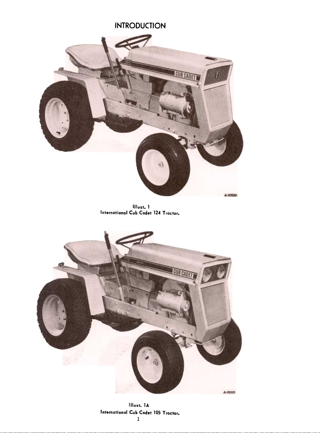
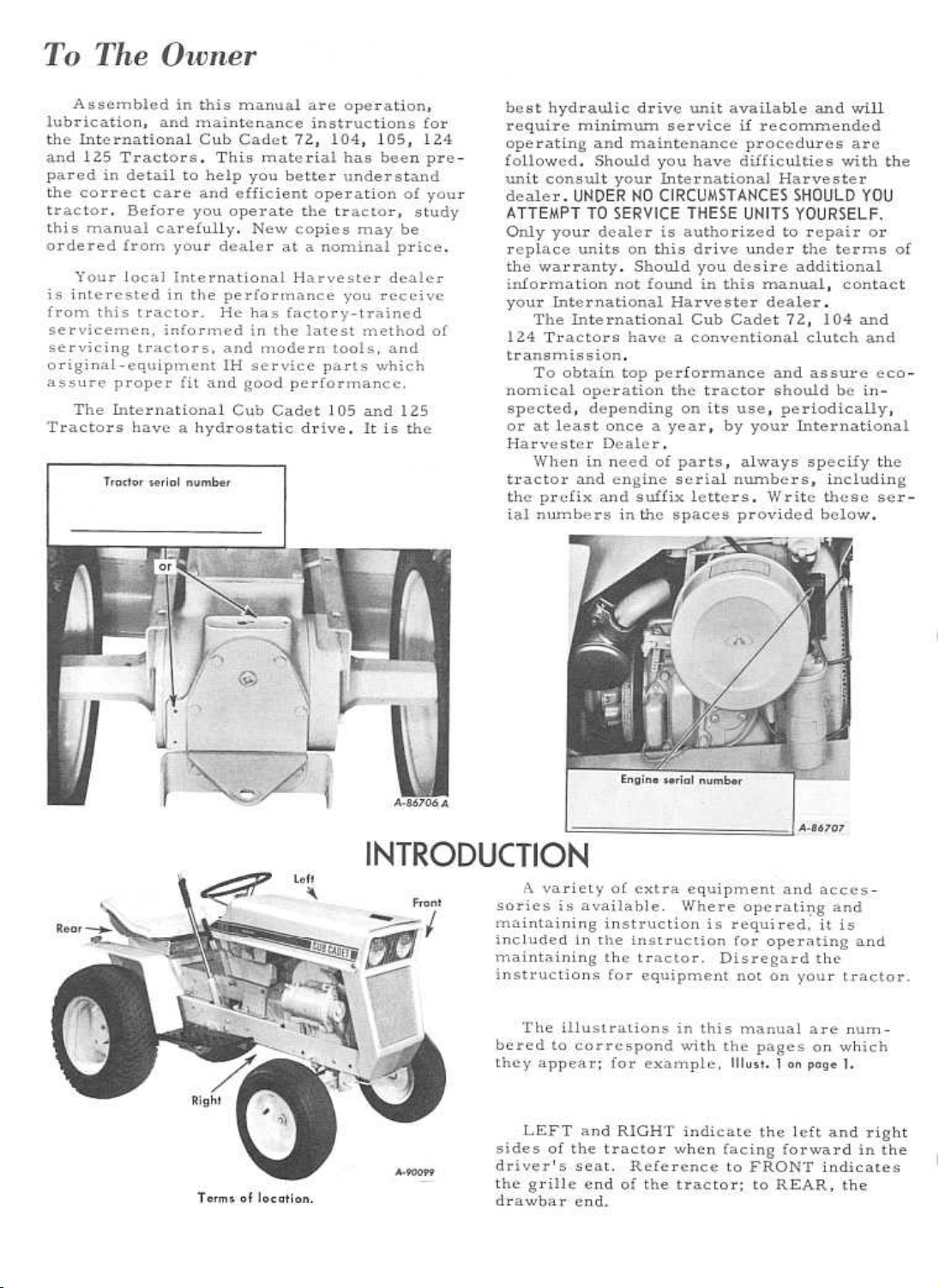
INTRODUCTION
International Cub Cadet 124 Tractor.
Illust. 1
(Ilust. 1A
International Cub Cadet 105 Tractor.
1
Page 4
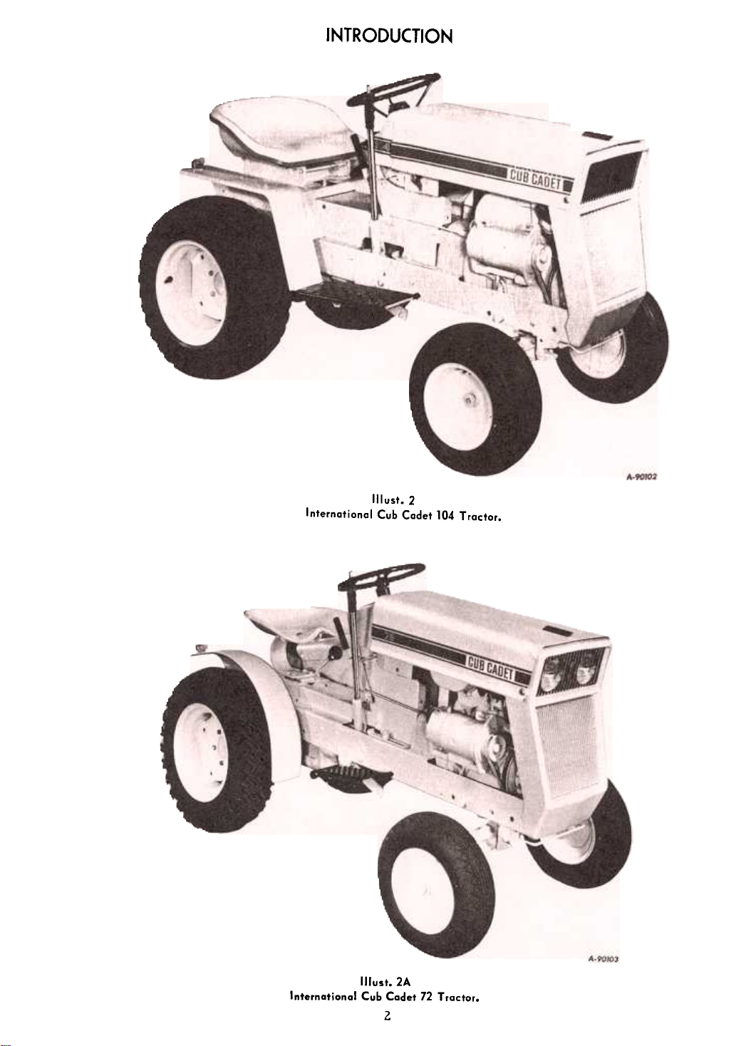
INTRODUCTION
Internatianal Cub Cadet 104 Tractor.
Illust.2
Illust. 2A
Internatianal Cub Cadet 72 Tractar.
2
Page 5
Page 6
Page 7
Page 8
Page 9
Page 10
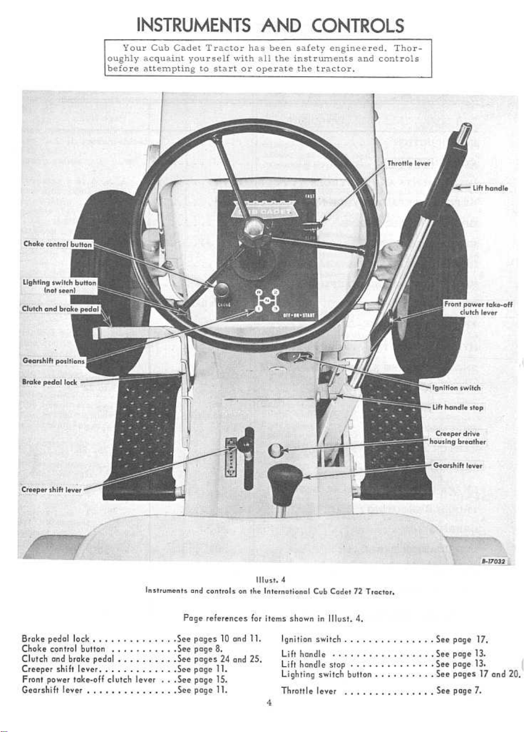
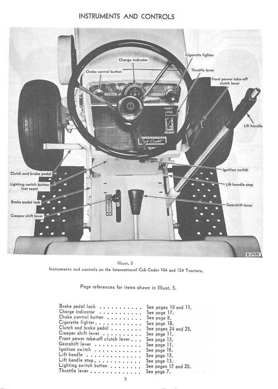
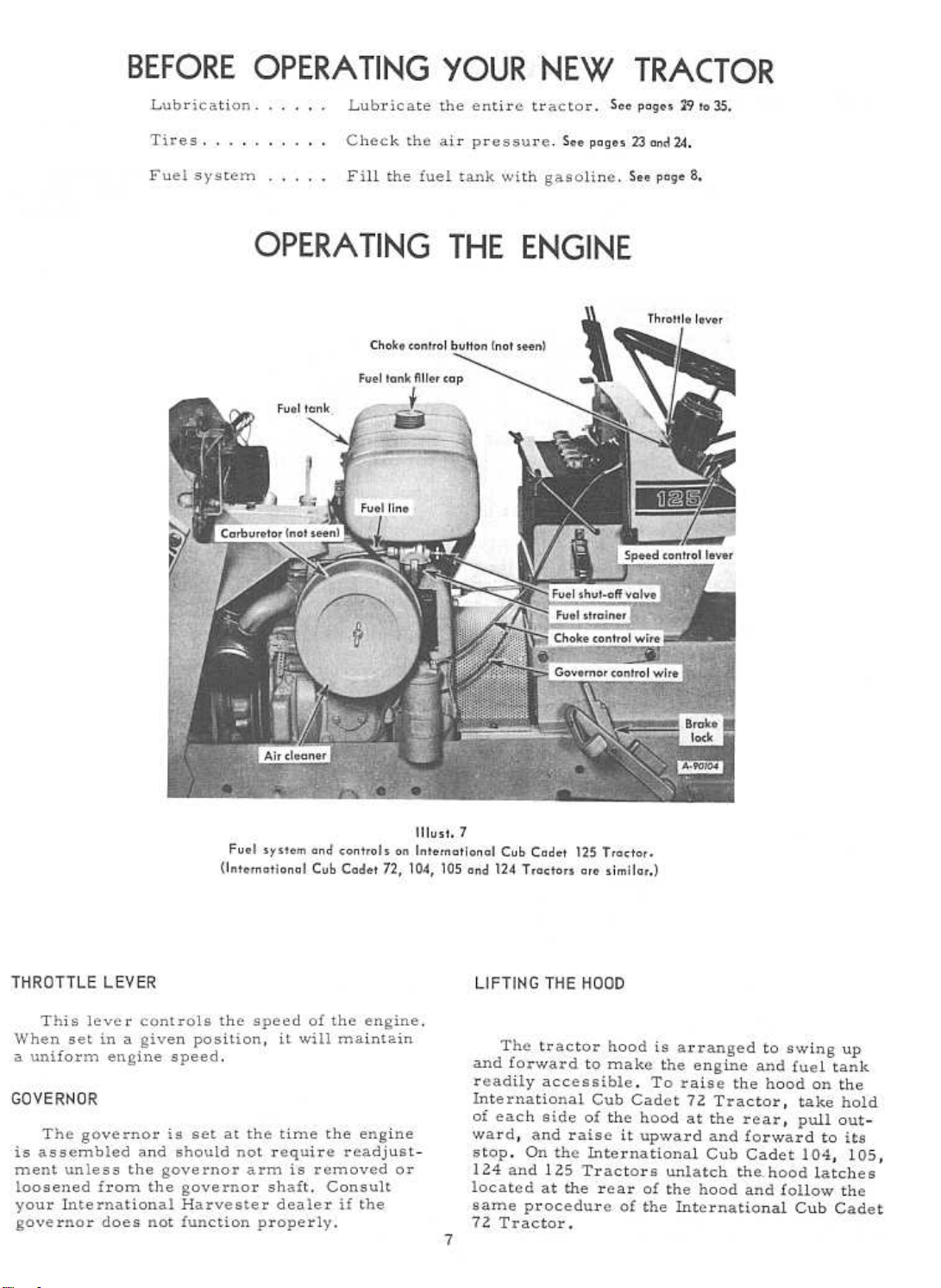
OPERATING THE ENGINE
STARTING THE ENGINE
Be sure the fuel shut-off valve is open.
2. Pull the choke control button all the way
out (see Illust.4or5}. More or less choking may be
necessary due to variations in temperature,
grade of fuel, etc. Little or none will be
needed when the engine is warm.
3. Place the throttle lever halfway between
"SLOW" and "FAST". See Illust. 4 or 5.
4. Electric Starting: The engine cannot be
started unless the brake pedal is pressed all
the way down to activate the safety starting
switch.
International Cub Cadet 72, 104, and 1'24 Tractors:
Check to see that the gearshift lever is in the
neutral position. See Illust. 4.
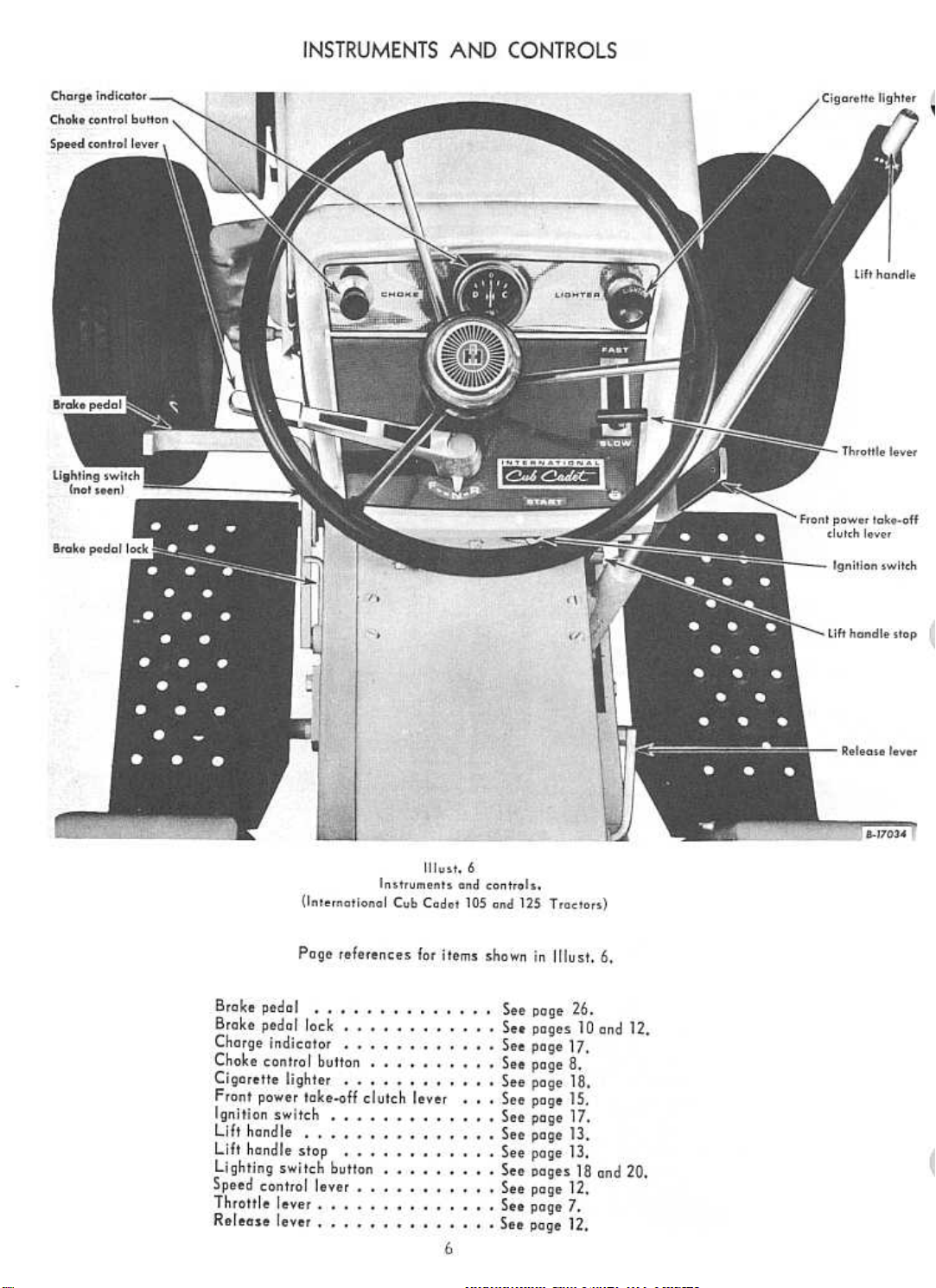
International Cub Cadet 105 and 125 Tractors:
Check to see that the speed control lever is in
th " N" ot O
All Models: Turn the ignition key clockwise
to the "START" position and release it as soon
as the engine starts; however do not operate the
motor-generator for more than 30 seconds at
anyone time. If the engine does not start within
this time, turn the key "OFF" and wait a few
minutes, then try again.
5. After the engine starts, slowly release
the brake pedal and gradually push the choke
Se pOSI Ions. ee Illust. 6.
control button all the way in. Do not use the
choke to enrich the fuel mixture, except when
necessary to start the engine.
Manual Starting '(Tractors without electric storting):
Raise the tractor hood. The retractable starter
is mounted on a support plate at the front of the
engin~ at the right side of the tr actor.
Put the gearshift lever in the neutral posi-
tion and lock the brake. Turn the key ignition
switch clockwise.
Give a quick steady pull on the retractable
starter handle to start the engine. Do not jerk,
or pull it out to its very end in a rough manner.
A steady pull will accomplish just as much.
Always pull the handle so the cord is in a
straight line through the guide. Maintain your
hold on the handle and allow the cord to returl}
slowly. Releasing the handle when the cable is
extended will shorten the life of the starter.
5. After the engine starts, slowly release
the clutch pedal and gradually push the choke
control button all the way in. Do not use the
choke to enrich the fuel mixture, except when
necessary to start the engine.
STOPPING THE ENGINE
Move the throttle lever to the "SLOW" po-
sition and allow the engine to idle for a short
time before stopping. Then turn the key to the
"OFF" position.
FUEL SYSTEM
Fill the fuel tank with clean, fresh, regular
grade gasoline, preferably at the end of each
day's use. This will force out any moistureladen air and prevent condensation in the fuel
tank. Do not mix oil with the gasoline.
The fuel tank filler cap has an ai.r vent.
Keep the vent open at all times to assure
proper flow of the fuel.
Caution! Never remove the fuel tank cap
or fill the fuel tank when the engine is running,
is hot, or when near an open flame. Do not
smoke when working around inflammable fuel,
as the air around the tractor is mixed with a
highly explosive vapor. When pouring fuel,
keep the container or hose nozzle in contact
with the metal of the fuel tank to avoid the
possibility of an electric spark igniting the
ga s. Do not spill ga s oline on a hot engine.
FUEL SHUT.OFF VALVE
Be sure the shut-off valve on the fuel
strainer under the gasoline tank is open.
Screw out the needle stem (Shut-off valve) until the seat on the stem is tight against the
stop, to prevent leakage or seepage when the
valve is in its full-open position.
CLEANING THE FUEL STRAINER AND SEDIMENT BOWL
After every 25 hours of operation, clean
the fuel strainer as follows:
1. Close the shut-off valve. See Illusts. 9 and 9A.
Loosen the knurled nut under the sediment
bowl and remove the bowl and screen.
2. Clean the sediment bowl and screen.
3. When reassembling, be sure the gasket
between the bowl and the main body is in good
condition and does not leak. Use a new gasket
if necessary.
8
Page 11
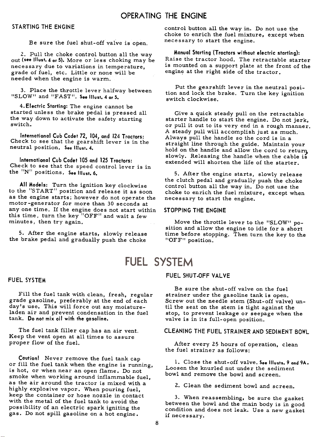
FUEL SYSTEM
Carburetor and fuel strainer.
Illust.9
(International Cub Cadet 72 Tractor)
CARBURETOR ADJUSTMENTS
The carburetor is adjusted at the factory
and under normal operating conditions it will
not require readjusting. If this adjustment has
been disturbed for any reason, proceed asfollows:
Adjusting the High-Speed Adjustment Screw
Turn the high speed adjustment screw (1IIusts.
9 and 9A) counter-clockwise approximately two
turns from the closed position and start the en-gine.
After the engine has reached normal oper~
ating temperature, accelerate the engine and
check its response.
Place the engine under load and turn the
high speed adjustment screw (1III/sts. 9 and 9A) to
the leanest mixture that will allow satisfactory
acceleration and steady governor operation.
If the engine misses and backfires under
load, the high speed mixture is too lean. The
high speed adjustment screw must be turned
counter-clockwise l/4 turn at a time until the
condition is corrected.
If the engine shows a sooty exhaust and is
sluggish under load, the high speed mixture is
too rich. The high speed adjustment screw
must be turned clockwise 1/4 turn at a time
until the condition is corrected.
9
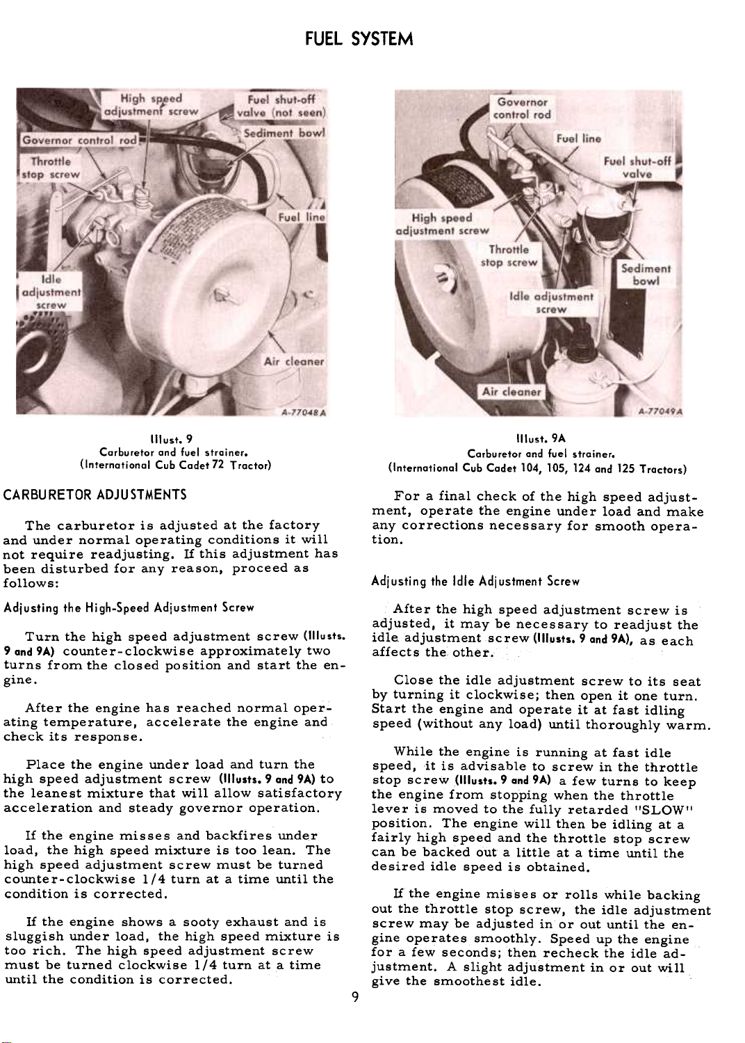
(1Iust.9A
Carburetar and fuel strainer.
(International Cub Cadet 104, 105, 124 and 125 Tractars)
For a final check of the high speed adjust-
ment, operate the engine under load and make
any corrections necessary for smooth opera-
tion.
Adjusting the Idle Adjustment Screw
After the high speed adjustment screw is
adjusted, it may be necessary to readjust the
idle. adjustment screw (1IIusts. 9 and 9A), as each
affects the other..
Close the idle adjustment screw to its seat
by turning it clockwise; then open it one turn.
Start the engine and operate it at fast idling
speed (without any load) until thoroughly warm.
While the engine is running at fast idle
speed, it is advisable to screw in the throttle
stop screw (1IIusts. 9 and 9A) a few turns to keep
the engine from stopping when the throttle
lever is moved to the fully retarded "SLOW"
position. The engine will then be idling at a
fairly high speed and the throttle stop screw
can be backed out a little at a time until the
desired idle speed is obtained.
If the engine mis'ses or rolls while backing
out the throttle stop screw, the idle adjustment
screw may be adjusted in or out until the en-
gine operates smoothly. Speed up the engine
for a few seconds; then recheck the idle ad-
justment. A slight adjustment in or out will
give the smoothest idle.
Page 12
PREPARING THE TRACTOR FOR EACH DAY'S WORK
Fill the fuel tank at the end of each day's
run. See page 8.
Check the crankcase oil level and add new
oil if ne ce s s ary. See page 29.
Clean the air cleaner element if necessary.
See page 17.
Inspect the tires for general condition. See
pages 23 and 24-
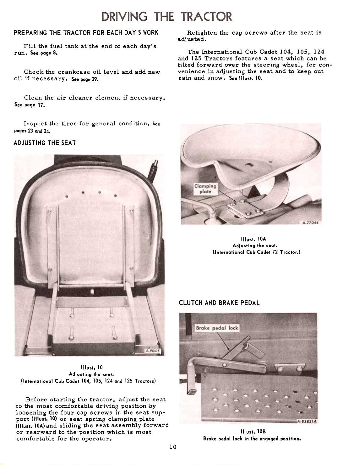
ADJUSTING THE SEAT
Retighten the cap screws after the seat is
adjusted.
The International Cub Cadet 104, lOS, 124
and 125 Tractors features a seat which can be
tilted forward over the steering wheel, for con-
venience in adjusting the seat and to keep out
rain and snow. See Illust. 10.
Illust. 10
Adj usting the seat.
(Internatianal Cub Cadet 104, 105, 124 and 125 Tractars)
Before starting the tractor, adjust the seat
to the most comfortable driving position by
loosening the four cap screws in the seat sup-
port (lllust. 10) or seat spring clamping plate
(lllust. lOA) and sliding the seat assembly forward
or rearward to the position which is most
comfortable for the operator.
Illust. lOA
Adjusting the seat.
(Internatianal Cub Cadet 72 T ractar.)
CLUTCH AND BRAKE PEDAL
III ust. lOB
Brake pedal lack in the engaged position.
10
Page 13
DRIVING THE TRACTOR
(I nternational Cub Cadet 12, 104 and 124 Tractors)
CLUTCH AND BRAKE PEDAL. Continued
The combination clutch and brake pedal is
used to disengage the engine from the trans-
mission when shifting gears and to actuate the
brake to stop the tractor. The pedal must be
pressed all the way down to activate the safety
starting switch when starting the engine.
To disengage the clutch, press the pedal
approximately half way down. To stop the tractor press the pedal all the way down.
LOCKING THE BRAKE
Note: Do not rest your foot on the pedal
while driving the tractor, as this will result
in excessive clutch lining wear.
Always be sure the rear wheels are free
to turn. Under any adverse conditions, do not
attempt to free the tractor by speeding up the
engine and suddenly engaging the clutch. Try
backing out instead of going forward.
STOPPING THE TRACTOR
Disengage the clutch by pressing the pedal
all the way down. Move the gearshift lever to
the neutral position.
Always lock the brake when the tractor is
parked on a grade. To lock the brake, press
down on the brake pedal; then place the brake
pedal lock in the engaged position. To disengage the lock, press down on the brake pedal
lift the lock up and place it in the disengaged
position behind the brake pedal as shown in
Illust. 7.
GEARSHIFT LEVER
This lever is used to select various gear
ratios provided in the transmission. There
are three forward speeds and one reverse
speed. See Illust. 4. Refer to "SPECIFICA TlaNS"
on page 35.
STARTING THE TRACTOR
1. Advance the throttle lever slightly. See
Illust. 4.
2. Disengage the clutch by pressing the
clutch pedal all the way down. and move the
gearshift lever to the desired speed.
CREEPER SHIFT LEVER
The creeper drive provides a slower speed
in each respective gear, by a four-to-one reduction in speed from direct drive. When the
creeper shift lever is all the way forward, it
is in direct drive, or all the way rearward, it
is in creeper drive. See 1(lust. 4. Note: Do not
use a mid-point position on the creeper drive
as neutral. Neutral position must be selected
only with the standard transmission gearshift
lever.
OPERATING THE CREEPER DRIVE
To operate the tractor in creeper drive,
move the creeper shift lever (1IIust.4) all the
way rearward. Then select the speed desired
and proceed as instructed under !'Starting the
Tractor".
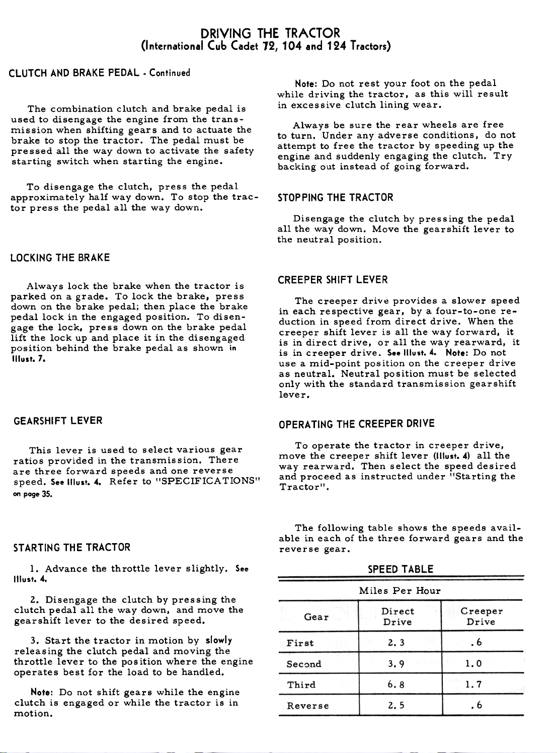
The following table shows the speeds avail-
able in each of the three forward gears and thereverse
gear.
SPEED TABLE
Miles Per Hour
Gear
Direct
Drive
Creeper
Drive
3. Start the tractor in motion by slowly
releasing the clutch pedal and moving the
throttle lever to the pos ition where the engine
operates best for the load to be handled.
Note: Do not shift gears while the engine
clutch is engaged or while the tractor is in
motion.
Reverse
First
Sec~nd
2.3
3.9
Third 6.8
2.5
.6
1.0
1.7
.6
Page 14
BRAKE PEDAL
DRIVING THE TRACTOR
(International Cub Cadet 105 and 125 Tractors)
The brake pedal must be pressed all the
way down to activate the safety starting switch.
When the brake pedal is in the depressed position it automatically moves the speed control
lever to the "Nil position.
The tractor can be stopped either by
pressing the pedal all the way down, or placing
the speed control lever in the I'NII position.
LOCKING THE BRAKE
Always lock the brake when dismounting
from the tractor. To lock the brake, press
down on the brake pedal; .then place the brake
pedal lock in the engaged position. S..lllust. 10B.
To disengage the lock, press down on the brake
pedal, lift the lock up and place it in the dis-
engaged position behind the brake pedal as
shown in Illust. 7.
SPEED CONTROL LEVER
This lever is used to select any speeds
from a standstill IINII position to eight miles
per hour in the forward direction and to four
miles per hour in the reverse direction.
Moving the speed control lever forward
provides increased forward speeds. and mov -
ing the lever rearward provides the reversed
speeds.
the tractor is used to hold the rotary tiller
back rather than to pull the unit, as in plowing or mowing.
4. Move the speed control lever back to a
position to maintain proper mulching of the
soil.
5. With a hydrostatic drive, it may be nec-
essary to vary the speed control lever as
the soil conditions vary. With a gear drive
tractor, under similar conditions, it may be
necessary to de clutch or to use the brake.
6. If desired depth cannot be obtained in the
first pass. additional passes will be neces-
sary. Do not use tine extensions when attempt-
ing deep penetration or when tilling heavy soil.
STARTING THE TRACTOR
1. Advance the throttle lever slightly. See
1!lust.6.
2. Dep~ess the brake pedal by pressing the
pedal all the way down, and move the towing
lever (I'luit. 6) in drive (horizontal) position,
then move the throttle lever to the position
where the engine operates best for the load to
be handled.
Note: Do not rest your foot on the brake
pedal while driving the tractor as this would
cause the speed control lever to return to the
!'N'I position.
Note: On tractors with a rotary tiller the
following instructions are required.
1. Engage the Power Take- Off clutch.
2. Lower the rotary tiller to the desired cut-
ting depth.
3. Move the speed control lever to start for-
ward motion. Note: In rotary tilling application,
Trailing-type equipment must be hitched to
the tractor only at the hitch hole in the draw-
bar. See Illusts. 13 and 13A.
When the tractor has a three-point hitch
(1IIusts. 13 and 13A) equipment adaptable to the
3. Start the tractor in motion by moving
the speed control lever forward or rearward
as described above.
RELEASE LEVER
To push or move tractor for a short distance
or when working on the engine, the release le-
ver (1IIust.6) must be locked in the release
(down) position and the speed control lever must
be in the "N" position. Caution: Do Not Tow.
STOPPING THE TRACTOR
Move the speed control lever to the I'NI'
position or use the brake. Before dismounting
always depress the brake pedal.
three-point hitch is raised and lowered with
the lift handle. The lift handle can be set to
hold the equipment at various positions by use
of the six notches in the lift handle quadrant.
The lower mounting bracket has three holes
which are used for additional adjustment.
12
Page 15

Page 16

Page 17

OPERATING THE FRONT POWER TAKE-OFF CLUTCH
1. Move the throttle lever back to medium
or low idle speed.
2. Move the front power take-off clutch
lever (forward) to the engaged position.
(rearward) to the disengaged position. See
'"usts. 4 or S.
The clutch is factory adjusted and should
not require further adjustment under normal
operating conditions. However, if clutch
slippage should occur. It is recommended
that you see your International Harvester
dealer for satisfactory servicing of the clutch,
as special equipment and instructions are
required.
Hote: It is recommended that the clutch
lever be placed in the forward or engaged
position when the tractor is being used without front power take -off equipment.
ADJUSTING THE CLUTCH
After considerable clutch use, it may be
necessary to readjust the button clearance as
described below to assure proper clutch dis-
engagement.
With the clutch fully engaged (clutch lever
in the forward position) place a piece of thin
cardboard (match book cover) approximately
1/64 inch thick between the engaging lever
wear button I'A'I and the pressure spring
thrust button "B'I (1IIust. 15), loosen the jam nut
on the clutch lever turnbuckle, and adjust the
turnbuckle until a light drag is felt on the
cardboard when it is removed from between
the buttons. Be sure all slack, except the
1/64 inch adjustment, is out of the linkage.
Then, tighten the jam nut securely against theturnbuckle.
It~ST ALLING AND REMOVING DRIVE BELT
Illust. 15
View with grille removed to show engoging
lever wear button and pressure spring
thrust button.
To install or remove the drive belt, loosenthe
clutch lever bolt enough so the lever can
be moved forward to provide sufficient belt
clearance between the engaging lever wear
button IIAII and the pressure spring thrust
button IIBII. See Illust. 15.
After installing a new belt, move the clutch
lever back onto the clutch lever latch and
tighten the bolt. See ttlust. 15.
15
Page 18

UNIT
Note: A slightly sluggish action of the con-
trollever returning to neutral may exist during
the break-in period. A few hours of running
will eliminate this. No adjustments are neces-sary.
To raise or lower front or rear mounted
equipment and to operate in "rigid ,. position,
the end clevis locking clip must be in the locked
position as shown in Illust. 16.
To operate equipment such as a mower in
"float" position, raise the end clevis locking
clip to the unlocked position.
Hydraulic unit assembled on the tractor.
Illust. 16
The hydraulic unit system is designed to
provide hydraulic power with fingertip control
for raising and lowering front or rear mounted
equipment.
This unit is a completely self-contained hy-
draulic gear pump with delivery of approximately 2-l/2-gallons per minute at pressures
up to 400 PSI, directional control valve, and
oil reservoir; with a companion hydraulic cyl-
inder and hoses connecting the power unit to
the cylinder. The unit has a built in safety
valve to eliminate overloading of the hydraulic
system and tractor attachments.
OPERATING INSTRUCTIONS
To familiarize yourself with the operation
of the hydraulic unit. start the tractor engine
and adjust the throttle to fast idle.
To raise the front or rear mounted equipment move the control lever rearward until the
desired height is reached, then release the
lever and it will return to the center or neutral
position. The equipment will "hold" in whatever position you desire depending upon when
you release the control lever. To lower the
equipment move the control lever forward. The
lever will again return to the neutral position
when you release it.
FILLING THE HYDRAULIC SYSTEM
Use IH Hy-Tranle> Fluid or a good quality
SAE -I OW engine oil.
Remove the oil filler plug from the hydraulic
pump and fill to the level of the filler plug opening then replace the plug. Fluid capacity is
approximately 3 pints.
Start the engine. adjust the throttle to fast
idle and test the hydraulic system. Check for
oil leaks at hose connections.
After the unit has been checked for opera-
tion, stop the engine, remove the oil filler plug
and add more fluid if necessary to bring it up to
the filler plug opening. Then replace the plug.
Note: Never run the hydraulic unit without
hydraulic fluid. WARRANTY WILL BE VOID
IF RUN WITHOUT FLUID.
16
Page 19

ENGINE COOLING
This tractor has an air cooled engine. Air
must be able to circulate freely around the
engine, through the screen and shroud, and
over the fins of the cylinder head and cylinderblock.
Keep these areas free of accumulated
dirt and trash or the engine will overheat and
result in damaged moving parts.
DRY-TYPE AIR CLEANER
Incoming air for combustion is filtered by
a dry-type air cleaner having a filter element
inside of the cover.
Remove and clean or replace the element
with a new one when loss of power is
noticeable.
Cleaning the Element if bent or cracked, then be sure the element
To clean the element, remove the wing nut cleaner base. The gasket sur~ace s of the ele-
and air cleaner cover (1IIust. 17) then remove the ment must be flat against the back plate and
element and tap it lightly on a flat surface to cover to seal effectively. The copper washer
cause the loose dirt to falloff. Handle the must be in place between the cover and the
paper element with care to avoid perforations. wing nut to seal and prevent unfiltered air from
Do not use compressed air to remove the dirt entering through the hole in the cover. Then
as this can rupture the element. Do not wash replace the cover and tighten the wing nut
or use a solvent. finger tight.
Replacing the Element
Replace the element with a new one if dirt
does not drop off easily, or if it is bent,
crushed or damaged. When replacing the ele-
ment be sure the back plate is securely tight-
ened to the carburetor. Replace the backplate
fits snugly around the inside edge of the air
Removing the air cleaner filter element.
Illust. 17
ELECTRICAL SYSTEM
The twelve-volt electrical system on a the tractor, the key must be turned to the
tractor with electric starting consists princi- "OFF" position to prevent battery discharge.
pally of a motor-generator, voltage regulator,
and a twelve-volt battery. SAFETY STARTING SWITCH
Use the illustrations on page 20 and wiring The safety starting switch activated by the
diagrams on page 21, as a guide for identifying clutch or brake pedal serve~ to prevent start-
the va~ious electrical units a?d for tracing the ing the engine accide~tally.
electrIcal cables and connectIons. Be sure all
connections are clean and securely fastened.
CHARGE INDICA TOR
IGNITION SWITCH
Turn the key clockwise to turn on the
ignition. With electric starting, a further turn~actuates
the motor-generator. The key cannot,be
removed when in the lION" position.
Note: When the t:ngine is not operating or
the engine has stalled and the operator leaves
17
~
This instrument (1!lust. 5) indicates whether
the motor-generator is charging or the battery
is discharging. If it shows discharge continuously, investigate the cause to avoid completely discharging the battery and possible
damage to the motor -generator. Refer to poge 22
for additional information on electrical equipment.
Page 20

LIGHTING SWITCH BUTTON
Pull the button (1IIust. 20A) out to turn on the
lights and push it in to turn off the lights.
CIGARETTE LIGHTER
Push the lighter to make electrical contact.
When it pops back it is ready for use.
SPARK PLUG
ELECTRICAL SYSTEM
IGNITION TIMING
Hote: Remove all dirt from the base of the
spark plug before removing the spark plug.
Remove the spark ~lug after every 100
hours of operation for cleaning and checking
the gap. See IJlust. 18. When making this adjust-
ment, always bend the outer electrode. Never
bend the center electrode. as it may damage
the insulator. If the gap between the electrodes
is too great, the engine will misfire and be
hard to start.
Always use a spark plug wrench when re-
moving or reinstalling the plug.
Be sure the gasket is in good condition,
and screw the plug in tightly. Do not tighten
more than enough to compress the gasket to
seal the plug and assure a good heat transfer
between the plug and the cylinder head. Tighten
the plug 1/2 to 3/4 turns past finger tight.
Adjusting the breaker points.
Cleaning the Spark Plug
Sandblasting is the recommended method of
cleaning the spark plug. Never scrape or clean
the insulator with anything which wiU scratch
the porcelain. Scratched porcelain allows
carbon and dirt to accumulate much faster.
Remove the breaker point cover after every
100 hours of operation for cleaning the points
and resetting the gap (1IIust. 18A). Replace badly
pitted or burned points.
For more precise timing, a timing light I
should be used. The engine has a timing sight
hole which is located in the right side of the
engine bearing plate on the International Cub
Cadet 72 Tractor or in the right side of the
blower housing in the International Cub Cadet
104, lOS, 124 and 125 Tractors. See "lust. 18B.
With the engine running at 1/3 throttle, or
more, adjust the breaker points until the "SP"
mark on the flywheel is centered in the sight
hole. Nate: The "SP" mark will appear 20 degrees before top dead center. The other mark
is the top center mark and is stamped with
"DC " below the mark.
Illust.18A
Set gap at .O20.inch.
Checking the spark plug gap.
Illust. 18
Set gap at .O25-inch.
Replace a defective plug with a new plug.
See your International Harvester dealer for a
correct replacement plug.
Location of timing sight hole.
Illust. 18B
(Motor-generator has been removed to better
illustrate the location).
18
Page 21

ELECTRICAL SYSTEM
MOTOR-GENERATOR
The motor-generator (12-volt, negative
ground) will function as a cranking motor when
the ignition key is turned to the "START"
position, driving the engine by means of a
belt.
When the engine is operating. the unit will
function as a generator.
MOTOR-GENERATOR BELT
Check the tension of the motor -generator
belt after the first 10 hours of operation and
every 50 hours of operation thereafter. The
tension is correct when the belt can be
deflected a maximum of 1/4-inch by a ten
pound force applied midway between the two
pulleys.
and Replacing the Motor-Generator Belt
Replace the motor-generator belt when it
becomes badly worn. To remove the old belt,
loosen the motor-generator brace bolt "A" and
mounting bolt,s "B", 1!lust. 20. Move the gener-
ator in toward the engine and slip the old belt
off the pulleys and over the crankshaft. Install
the new belt in the reverse order of removal
and adjust the belt to the proper tension.
VOL TAGE REGULATOR
A satisfactory generator charging rate is
maintained by the voltage regulator. If the
regulator fails to operate correctly, see your
International Harvester dealer.
Note: Never place a jumper lead between,
or accidentally bridge, the "BAT'I terminal
and the IIF'I terminal on the regulator, as this
will damage the regulator.
Correct motor-generotor belt tension.
Illust.19
Also follow this procedure when a new belt
is installed.
Adjusting the Motor-Generator Belt
Loosen the motor-generator brace bolt flAIland
mounting bolts f'B", Illust. 20.
Move the generator away from the engine
until the tension on the belt is correct. See
Illust. 19.
Note: Under no circumstances should a pry
bar be used on the motor -generator to obtain
belt tension as damage to the bearings will
ire suIt.
Tighten mounting bolts "B" and brace bolt
"A".
The headlights are sealed-beam lights. The
parts are so constructed that the filament, re-
flector, and lens are all assembled in a unit
permanently sealed against dirt, moisture,
and corrosion. If a filament burns out or a
lens breaks, the complete unit must be replaced. Refer to "SPECIFICA TIONS't.
TAILLIGHT
To replace the taillight lamp, remove the
lens from the taillight and replace the taillight
lamp with a 4 candle power lamp. Refer to
"SPECIFICATIONS".
FUSE (Electric Lighting)
It is important to use the same capacity
fuse for replacement. Refer to "Specifications ". If the lights fail, check the fuse. If a
fuse continually burns out, check the electri-
cal wiring for short circuits.
The fuse is located in a fuse housing in the
line at the back of the instrument panel. See
Illust.21.
To install a new fuse, press in on the fuse
housing cap and turn counterclockwise to remove it from the fuse housing. Remove the old
fuse and replace it with a new one. Then re-
assemble the cap to the housing. Remove the
battery if necessary to reach the fuse.
lq
Removing
LIGHTS
Page 22

ELECTRICAL SYSTEM
Electrical units an the right side af the tractor.
Jllust.20
Electrical units on the left side of the tractor.
"lust. 20A
20
Page 23

Page 24

ELECTRICAL SYSTEM
Index to reference numbers shown in Illust. 21A.
No.
Cable -lighting switch to headlamp
junction -violet.
Cable -key switch "BAT" terminal to
charge indicator "NEa. II terminal -
light green.
Cable assembly. Charge indicator to
magnetic switch.
Cable -charge indicator lINEa. II ter-
4
minal to regulator "BA T" terminal-
gray.
Cable -battery positive (+) terminal to
5
magnetic switch.
Cable -battery neg.ative (-) terminal to
6
motor generator ground -white.
Cable -safety starting switch to mag-
netic switch -orange w/black tracer.
Description
STORAGE BATTERY
Battery and Cabl es
Before working on any part of the electri-
cal system, disconnect the battery ground
cable at the battery negative (-) terminal. See
Illust.20. Do not reconnect this cable until all
work has been completed. This will prevent
shorting and damage to any of the electrical
units. Examine the electrical cables occasion-
ally to be sure they are not being frayed by
contact with adjacent parts.
When replacing a battery, make certain the
ground cable is connected to the negative (-)
terminal on the battery. Be sure the rubber
boot is properly positioned over the positive
(+) terminal on the battery. Note: Both cables
must be assembled with the nuts to the inside
of the terminals to prevent shorting against
the pedestal.
Ref.
No.
8
Cable -magnetic switch to generator 'IA'I
terminal -red.
Cable -safety starting switch to key ig-
9
nition switch "ST" terminal -orange.
10
Cable -ignition coil positive (+) ter-
minal to key ignition switch "IGN"
terminal -black.Cable
11
12
Cable -regulator "GEN" terminal to
generator "A" terminal -light blue.Cable
13
lator base ground -white with black
tracer.Cable
14
age regulator "F" terminal -yellow.
Keeping the battery fully charged not only
adds to its life but makes it available for instantuse
when needed.
Level
Description
harness.
-ground junction to voltage regu-
-generator "F" terminal to volt-
Check the battery at least once a month for
water level.
The electrolyte (acid and water) in each
cell should be at ring level at all times to pre-
vent battery failure. When the electrolyte is
below this level, add pure, distilled water.
Acid or electrolyte should never be added
except by a skilled battery man. Under no
circumstances add any special battery 'Idopes, II
solutions or powders.
Caution! Electric storage batteries give off
highly inflammable hydrogen gas when charging and continue to do so for some time after
receiving a steady charge.
Cleaning and Servicing the Battery
Occasionally remove the battery cables and
brighten the terminal contact surfaces with
wire wool, and reassemble them. Apply a
light coat of vaseline or chassis lubricant. Be
sure the terminals are clamped tightly and
that the battery is fastened securely in the battery box. Replace unserviceable cable. Keep
the vent holes in the battery filler caps open.
Ref.
1
3
7
Liquid
Caution! Do not under any circumstances
allow an electric spark or an open flame near
the battery. Do not lay tools across battery
terminals as this may result in a spark or
short circuit which may cause an explosion.
Be careful to avoid spilling any electrolyte
on hands or clothing.
For dependable battery service, see your
International Harvester dealer.
22
Page 25

FRONT WHEEL TOE-IN
Front wheel odjustments.
Illust. 23
Illust. 23A
Tie rod ond drog link ball joints.
The front wheel toe-in dimension is 1-32-
inch to liS-inch toe-in (1/32-inch to liS-inch
closer in front than in the rear). Measure the
distance between two points "A'I and two points
"B" Illust.23. Points "A'! and "B" must be on the
inside of the wheels at the outer edges and at
the same height from the ground as the front
wheel hubs.
To adjust the toe-in, disconnect either
tie rod ball joint "C" (1IIusts. 23 and 23A) loosen
REAR TIRES
6-12 rear tires are standard equipment on
the International Cub Cadet 72, 104, and 105
Tractors.
23 x 8.50 -12 Terra-Tires are standard
equipment on the International Cub Cadet 124
and 125 Tractors. They are also available as
extra equipment when ordered for the
International Cub Cadet 72, 104, and 105
Tractors.
the lock nut, and turn the tie rod ball joint
end in or out as required.
TURNING RADIUS
The front wheels should have an equal angle
for left and right turns. If adjustment is nec-
essary, disconnect the drag link ball joint I'D'!
(1IIusts. 23 and 23...) loosen the lock nuts and turn
the drag link ball joint in or out as required.
Keep tires free from oil and grease as both
destroy rubber.
After using the tractor for spraying-insect
control work-use water to remove any chem-
icals that may be on the tires.
The Terra-Tires provide maximum mobility
in sand, snow, and soft soil conditions. The
reduced ground pressure and low inflation
provides maximum protection for turf, soil,
and crops.
CARE OF TIRES
Avoid stumps, stones, deep ruts, and other
hazards. Cuts in tires should be repaired
immediately as neglect decreases the tire life.
INFLATION
Keep the pneumatic tires properly inflated.
Underinflation will damage the tire cord body
and may also cause the tire to slip on the rim,
thus tearing out the tube valve stem.
Always see that the tire valve caps are in
place and tightened securely to prevent the
loss of air and protect the valve core and stem.
23
Page 26

Page 27

CLUTCH AND BRAKE
(International Cub Cadet 72, 104 and 124 Tractors)
As the clutch and brake are both operated
by the same pedal, care must be taken to
maintain a neutral zone so the clutch is dis-
engaged when the brake is applied.
ADJUSTING THE CLUTCH
It is important that a clearance of .050inch be maintained between the clutch release
lever and the clutch release bearing. In order
to maintain this clearance. the pedal should
have a free movement of approximately 3/16-
inch. See Illust. 24. This measurement is taken
at the point of contact of the pedal arm with
the front edge of the pedal return stop.
The clutch pedal adjustments are set at the
factory and should not require frequent attention unless the linkage has been disturbed or
when the pedal movement becomes less than
3/ l6-inch. When it is necessary to adjust the
clutch, turn the adjusting nut !'AII on the clutch
release rod (1IIust. 25) in or out as required to
get the proper measurements.
ADJUSTING THE BRAKE
The brake should engage when the pedal
arm is pressed down to within a maximum of
l-5/l6-inches and a minimum of 3/4-inch distance above the top of the left foot support,
which serves as the pedal stop. See IIIust. 24.
It may be possible to push the pedal all the
way down to the pedal stop, but this is of no
concern as long as the brake is engaged when
the pedal a-rm is at least 3/4-inch above ttlepedal
stop.
To adjust the brake, loosen the jam nut
"B" and turn the brake lever adjusting screw
lICIt (1IIust. 25) in or out as required to get this
measurement. The brake must not engage
before the pedal arm is within the maximum
distance of 1-5/16-inches above the pedal stop.
Illust. 25
Clutch and brake adjustments.
25
Page 28

BRAKE
(International Cub Cadet 105 and 125 Tractors)
Brake adjustments.
ADJUSTING THE BRAKE
The brake should engage when the pedal
arm is pressed down to within a maximum of
1-5/16-inches and a minimum of 3/4-inch dis-
tance above the top of the left foot support,
which serves as the pedal stop. See Illust. 26.
It may be possible to push the pedal all the
way down to the pedal stop, but this is of no
concern as long as the brake is engaged when
the pedal arm is at least 3/4 -inch above the
pedal stop.
To adjust the brake. loosen the jam nut "B"
and turn the brake lever adjusting screw "c"
(1IIust. 26A) in or out as required to get this
measurement. The brake must not engage
before the pedal arm is within the maximum
distance of 1-5/16-inches above the pedal stop.
ADJUSTING THE SPEED CONTROL LEVER
Note: The brake pedal must be properly ad-
justed before beginning the speed control lever
adjustment. If the tractor "creeps" in the "N"
position or, if the speed control linkage has
been disassembled or removed for any reason,
the following adjustment must be made.
Block the tractor so the left rear wheel is
off the ground.
Start the engine at half throttle or faster.
Move the speed control lever to the forward
position. The rear wheel should rotate in the
forward direction. Depress the brake pedal all
the way down and release. The speed control
lever should return to the "N" position and the
rear wheel stop turning.
1£ the rear wheel turns in the forward direc-
tion, loosen jam nut "D" and turn the connect-
ing rod I'E" counterclockwise to lengthen it
until the wheel stops turning. (See Illust. 26A).
A-86719 A
Illust.26
If the wheel turns in the reverse direction
turn the connecting rod l'Elf clockwise.
Tighten the jam nut I'DI'.
If this adjustment does not stop "creeping
see your International Harvester dealer.
Illust. 26A
Brake adjustments.
26
=,
Page 29

Page 30

Page 31

TROUBLE SHOOTING
Possible Cause
Possible Remedy
LACK OF POWER -Continued
Incorrect timing or faulty ignition. Clutch slipping (Models 72, 104 and 124)
See "Breaker Points and Spark Plug" on pages
18 and 19.
Adjust the free travel of the pedal; see pages 24
Brake drags.
and 25.
Adjust the brake; see pages 24 and 25.
ENGINE OVERHEATS
Insufficient cool air, dirty air intake screen, Keep the air intake area and cooling fins clean;
shroud, or cooling fins. See "Engine Cooling and Air Cleaner"
on poge 17.
CREEPING
Speed control lever out of adjustment (Models 105 and 125) See !'Speed Cont,rol Lever Adjustment!'
on poge 26.
':' See your International Harvester dealer.
ENGINE OIL
The tractor is shipped from the factory
with shipaway engine oil in the crankcase. If
the engine is to be operated at temperatures
between +75 degrees F and 0 degrees F, this
oil can be used for the first five hours of
operation. If the temperatures are not within
this range, drain the oil from the crankcase
and replace it with new oil as specified in the
II Lubrication T able", The engine oil must be
drained and replaced with new oil every 30hours
of engine operation thereafter.
Oils designated "For Service MS" are
recommended for this engine.
To aid starting. the selection of crankcase
lubricating oils should be based on the lowest
anticipated temperature until the next drain
period.
Check the oil levels of the engine crankcase and transmission to see that they are
filled to the correct levels. Note: Check the
oil level only while the engine is stopped.
Illust.29
Oil level gauge.
29
Page 32

Page 33

Page 34

-Oil filler cap and bayonet-type
oil level gauge.
2- Steering knuckles (2).
3- Front oxle pivot pin.
4 -Engine crankcase.
LUBRICATION GUIDE
(International Cub Cadet 72, 104 and 124 Tractors)
--After Every 10 Hours of Operation
Check the oil (with the engine stopped) and add sufficient
new oil to bring it to the "FULL" mark on the gauge. Do
not overfill. Do not operate the engine if the oil level is
below the "LOW" mark on the gauge.
Use IH-25lH EP grease or equivalent #2 multi-purpose
lithium grease and apply sufficient grease to flush out oldgrease
and dirt.
--After Every 30 Hours of Operation
While the oil is warm, remove the drain plug (4) and drain
all of the oil from the crankcase. Replace the drain plug.Remove
the crankcase oil filler (;ap (1). Refill the crank-
case with new oil up to the "FULL" mark on the oil levelgauge.
Refer to the "Lubrication Table" for the proper
quantity and viscosity to use.
--After Every 100 Hours of Operation
take-off shaft bearing
Transmission
6. Oil level and filler plug.
7. Oil drain plug.
Creeper drive housing
8. Level plug.
9. Breather and filler plug.
10. Drain plug.
11 .Steering gear hausing.
Miscellaneou§
Use IH -25lH EP grease or equivalent #2 multi-purpose
lithium grease and apply two or three strokes of the lubricator to the lubrication fittings.
--Periodic
Check the oil level periodically. Keep the lubricant up to
the level plug (6) on the rear of the transmission case.
Change the oil in the transmission case at least once a
year. Remove the drain plug (7) and remove the oil level
and filler plug (6) and allow all of the oil to drain out. Replace the drain plug. Refill with approved lubricant up to
the level plug opening and replace the plug.
Check the oil level periodically. Keep the lubricant up to
the level plug (8) on the left side of the creeper drive
housing. Drain and refill the housing each time the oil is
changed in the transmission case. To change the oil, remove the drain plug (10) at the bottom of the housing and
allow all the oil to drain. Then replace the drain plug.
Remove the breather and oil filler plug (9) at the right
of the creeper shift handle on top of the frame assembly,
and remove the oil level plug (8). Fill to the level plug
opening with approved lubricant and replace the plugs.
\
Once a year, apply two strokes of the lubricator, using
ill-251H EP grease or equivalent #2 multi-purpose lithium
grease.
Note: To locate the lubrication fitting, turn the front
wheels to the maximum right turn position. Then reach up
under the right side of the tractor frame to locate the
fitting.
Lubricate the clutch pedal shaft and linkage with eight or
ten drops of engine oil.
S-Power
31.
Page 35

Page 36

LUBRICATION GUIDE
(International Cub Cadet 105 and 125 Tractors)
--After Every 10 Hours of Operation
1. Oil filler cap and bayonet-type
ail level gauge.
2. Steering knuckles (2).
3. Front axle pivot pin.
4. Transmission ail filter,
S. Engine crankcase.
Check the oil (with the engine stopped) and add sufficient
new oil to bring it to the "FULL" mark on the gauge. Do
not overfill. Do not operate the engine if the oil level is
below the "LOW" mark on the gauge.
Use IH-25lH EP grease or equivalent #2 multi-purpose
lithium grease and apply sufficient grease to flush out old
grease and dirt.
Note: After the first 10 hours only, remove the old filter
and replace with a new filter as instructed on page 30.
Change the oil filter after 50 hours and every 100 hours
of operation thereafter.
--After Every 30 Hours of Operation
While the oil is warm, remove the drain plug (5) and
drain all of the oil from the crankcase. Replace the drain
plug. Remove the crankcase oil filler cap (I). Refill the
crankcase with new oil up to the "FULL" mark on the oil
level gauge. Refer to the "Lubrication Table" for the
proper quantity and viscosity to use.
--After Every 50 Hours of Operotion
6. Transmission oil filter.
7. Transmission oil filter.
Transmission
Oil level and filler plug.
Note: After the first 50 hours only, remove the old filter
and replace with a new filter as instructed on poge 30.
Change the oil filter every 100 hours of operation
thereafter.
.
--After Every 100 Hours of Operation
Change the oil filter and replace with a new filter as
instructed on poge 30.
--Periodi c
Check the oil level periodically. Keep the lubricant up to
the level plug (8) on the rear of the transmission casecover.
34
8.
Page 37

Page 38

Page 39

Page 40

Page 41

MEMORANDA
39
Page 42

MEMORANDA
40
Page 43

MEMBER, NATIONAL SAFETY COUNCIL
Accidents
No accident-prevention program can be successful without the wholehearted co-operation
of the person who is directly responsible for the
operation of equipment.
To read accident reports from allover the
country is to be convinced that a large number
of accidents can be prevented only by the
operator anticipating the result before the
accident is caused and doing something about
it. No power-driven equipment, whether it be
transportation or processing, whether it be on
the highway, in the harvest field or in the
Price $1.00
be
industrial plant, can be safer than the man who
is at the controls. If accidents are to be prevented-and they can be prevented-it will be
done by the operators who accept a full measure
of their responsibility.
It is true that the designer, the manufacturer,
the safety engineer can help; and they will help,
but their combined efforts can be wiped out by
a single careless act of the operator.
It is said that r 'the best kind of a safety
device is a careful operator. II We ask you
to be that kind of an operator.
Page 44

 Loading...