

Page 1
Illustrated Parts Manual
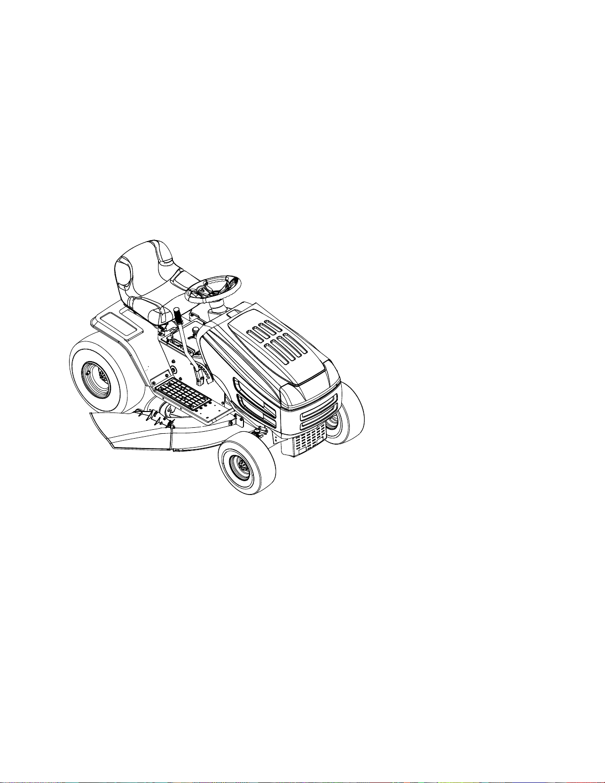
Transmatic Lawn Tractor
MODELS 660, 680
662, 682
663, 683
665, 685
668, 688
PRINTED IN U.S.A.
MTD LLC, P.O. BOX 361131 CLEVELAND, OHIO 44136-9722
FORM NO.
769-00642B.fm
(10/24/2003)
Page 2
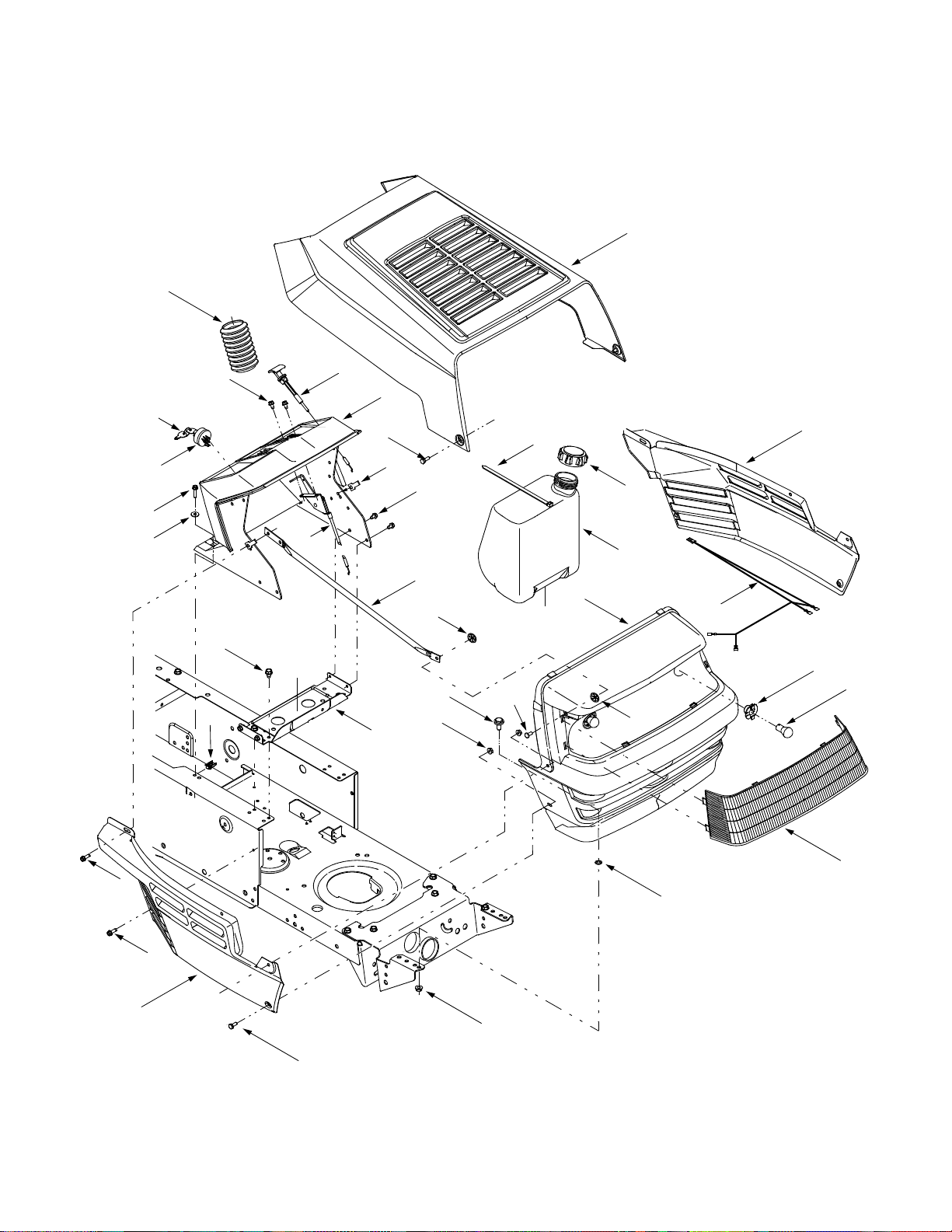
Model
s 660, 665, 680 & 685
12
34
25
29
18
17
26
24
23
28
A
33
10
22
27
B
30
3
23
11
†
†
7
9
†
5
†
1
16
A
31
32
7
13
‡
21
‡
15
14
20
8
2
6
‡
2
‡
B
4
‡
19
†
Found on Models 660 & 6
‡
Found on Models 665 & 68
2
80 Only
5 Only
Page 3

Models 660, 665, 680 & 685
REF.
NO.
1 728-0162 Flat-head Rivet, 1/4
2 710-0642 Self-tapping Screw, 1/4-20 x .75
3 712-0185 U-type Speed Nut, 1/4-20
4 712-0429 Lock Nut, 5/16-18
5 712-0324 Lock Nut, 1/4-20
6 726-0201 Speed Nut, .3125
7 726-04012 Push-on Nut, .25
8 731-1099A Lens
9 738-04015 Shoulder Screw, 5/16-18 x .625
10 738-0952A Shoulder Screw, 1/4-20 x .375 /.125
11 749-0722C Grille Support Rod
12 783-0250A Hood w/ Louvers
13 629-0469B Headlamp Harness Assembly
14 725-0963 Headlamp, 12V
15 725-1649 Headlamp Socket
16 731-1097F Grille
17 725-1396 Ignition Switch, 6-pin
18 725-0201 Keys (pair)
19 710-0751 Hex Screw, 1/4-20 x .620
20 783-0150B RH Side Panel
21 783-0151B LH Side Panel
22 17632D Support Bracket
23 710-0599 Self-tapping Screw, 1/4-20 x .5
24 710-0607 Self-tapping Screw, 5/16-18 x .5
25 710-0788 Self-tapping Screw, 1/4-20 x 1.0
26 726-3054 U-type Speed Nut, 1/4-20
27 731-04179 Dash Panel (models w/o choke knob)
28 746-04020A Throttle / Choke Control, 18.5”
29 736-3090 Flat Washer, .260 x .720 x .060
30 726-0230 Cable Tie, 34.75
31 751-0555B Fuel Tank, 1.5 gal.
32 751-0603 Fuel Tank Cap
33 746-0614A Choke Control, 38”
34 731-0954 Steering Bellow, 4.75”
PART
NO. DESCRIPTION
731-04082 Dash Panel (models w/ choke knob)
746-04023A Throttle Control, 35.5”
746-04030A Throttle Control, 18.5”
746-0616A Choke Control, 23”
NOTE: Tractor features vary by model. NOT all parts listed above and pictured on the previous page are standard equipment.
3
Page 4
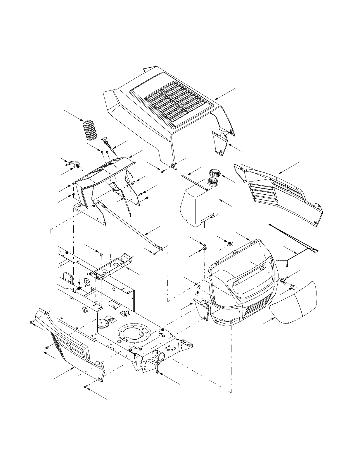
Model
s 662, 663, 682 & 683
17
36
28
32
23
22
29
27
26
24
30
14
5
26
31
†
15
†
A
11
25
B
33
16
†
A
4
13
7
10
35
34
19
†
1
8
‡
21
9
2
20
†
18
12
‡
2
‡
B
6
3
†
Found on Models 662 & 6
‡
Found on Models 663 & 68
4
82 Only
3 Only
Page 5

Models 662, 663, 682 & 683
REF.
NO.
1 629-0469B Headlamp Harness Assembly
2 710-0642 Self-tapping Screw, 1/4-20 x .75
3 710-0751 Hex Screw, 1/4-20 x .620
4 710-3008 Hex Screw, 5/16-18 x .75
5 712-0185 U-type Speed Nut, 1/4-20
6 712-0429 Lock Nut, 5/16-18
7 712-3027 Lock Nut, 1/4-20
8 725-0963 Headlamp, 12V
9 725-1651 Headlamp Socket
10 726-04012 Push-on Nut, .25
11 728-0162 Flat-head Rivet, 1/4
12 731-1503A Lens
13 736-3078 Flat Washer, .344 x 1.0 x .063
14 738-0952A Shoulder Screw, 1/4-20 x .375 /.125
15 749-0722C Grille Support Rod
16 783-0156B Grille
17 783-0250A Hood w/ Louvers
18 783-0366 RH Side Panel (Insert)
19 783-0367 LH Side Panel (Insert)
20 783-0150B RH Side Panel
21 783-0367 LH Side Panel
22 725-1396 Ignition Switch, 6-pin
23 725-0201 Keys (pair)
24 746-0614A Choke Control, 38”
25 17632D Battery Support Bracket
26 710-0599 Self-tapping Screw, 1/4-20 x .5
27 710-0607 Self-tapping Screw, 5/16-18 x .5
28 710-0788 Self-tapping Screw, 1/4-20 x 1.0
29 726-3054 U-type Speed Nut, 1/4-20
30 731-04179 Dash Panel (models w/o choke knob)
31 746-04020A Throttle / Choke Control, 18.5”
32 736-3090 Flat Washer, .260 x .720 x .060
33 726-0209 Cable Tie, 30.66
34 751-0555B Fuel Tank, 1.5 gal.
35 751-0603 Fuel Tank Cap
36 731-0954 Steering Bellow, 4.75”
PART
NO. DESCRIPTION
746-0616A Choke Control, 23”
731-04082 Dash Panel (models w/ choke knob)
746-04023A Throttle Control, 35.5”
746-04030A Throttle Control, 18.5”
NOTE: Tractor features vary by model. NOT all parts listed above and pictured on the previous page are standard equipment.
5
Page 6
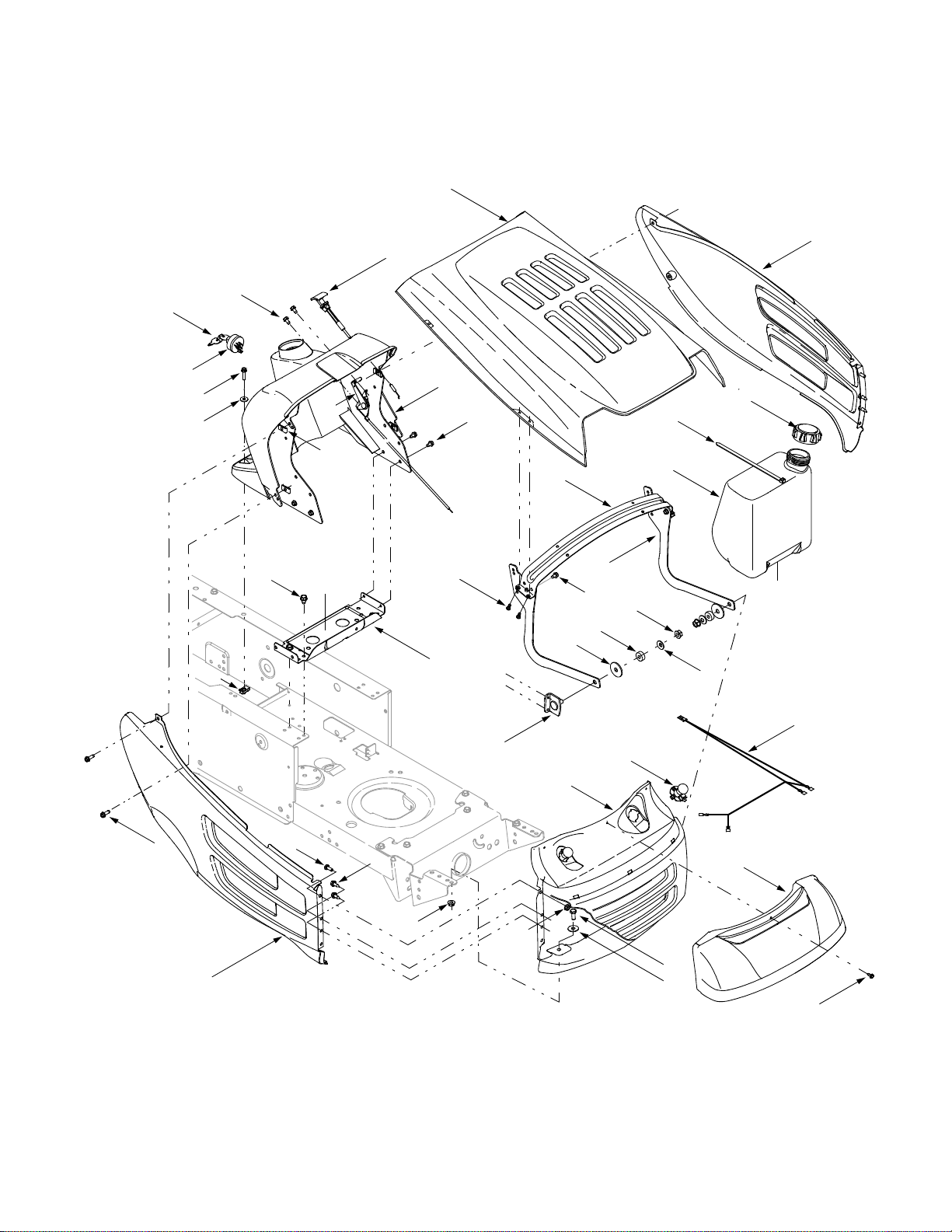
Models 66
18
8 & 688
25
22
34
5
39
30
33
31
29
35
10
A
28
32
38
11
36
37
A
19
1
5
26
3
27
5
17
20
B
2
14/15
24
6
23
7
8
12
6
13
B
9
21
16
4
Page 7

Models 668 & 688
REF.
NO.
1 629-0469B Headlamp Harness Assembly
2 683-0195 Bracket Assembly
3 710-0351 Screw, #10-16 x .50
4 710-0456 Screw, #10-16 x .50
5 710-0599 Self-tapping Screw, 1/4-20 x .5
6 710-0642 Self-tapping Screw, 1/4-20 x .75
7 710-0751 Hex Cap Screw:1/4-20 x .620
8 710-0896 Hex Index Washer Screw, 1/4-14 x .0625
9 710-3008 Hex Screw, 5/16-18 x .75
10 712-0185 U-type Speed Nut, 1/4-20
11 712-0431 Flange Lock Nut, 3/8-16
12 712-0429 Lock Nut, 5/16-18
13 712-3027 Flange Lock Nut, 1/4-20
14 725-0963 Headlamp, 12V
15 725-1649 Headlamp Socket
16 731-1854A Headlight Lens (8-style)
17 735-0126 Rubber Washer, .87 x .33
18 725-0201 Keys (pair)
19 736-0300 Flat Washer, .406 x .875 x .059
20 736-3039 Flat Washer, .406 x 1.5 x 11 gauge
21 736-3078 Flat Washer, .344 x 1.0 x .063
22 783-0475B LH Side Panel
23 783-0476C RH Side Panel
24 783-0477A Grille
25 783-0478B Hood
26 783-0553A Hood Support Bracket
27 783-1495 Hood Side Bracket
28 17632D Battery Support Bracket
29 710-0607 Self-tapping Screw, 5/16-18 x .5
30 710-0788 Self-tapping Screw, 1/4-20 x 1.0
31 726-3054 U-type Speed Nut, 1/4-20
32 731-04180 Dash Panel (models w/o choke knob)
33 736-3090 Flat Washer, .260 x .720 x .060
34 746-0614A Choke Control, 38”
35 746-04020A Throttle / Choke Control, 18.5”
36 726-0209 Cable Tie, 30.66
37 751-0555B Fuel Tank, 1.5 gal.
38 751-0603 Fuel Tank Cap
39 725-1396 Ignition Switch, 6-pin
PART
NO. DESCRIPTION
731-04080A Dash Panel (models w/ choke knob)
746-0616A Choke Control, 23”
746-04023A Throttle Control, 35.5”
746-04030A Throttle Control, 18.5”
NOTE: Tractor features vary by model. NOT all parts listed above and pictured on the previous page are standard equipment.
7
Page 8
Model
3
s 660 – 688
21
4
19
35
24
22
1
37
5
34
11
25
13
33
17
27
23
15
29
6
32
38
20
8
10
14
11
11
30
7
10
16
36
12
28
39
26
2
12
31
9
36
16
18
12
42
41
43
44
40
8
Page 9

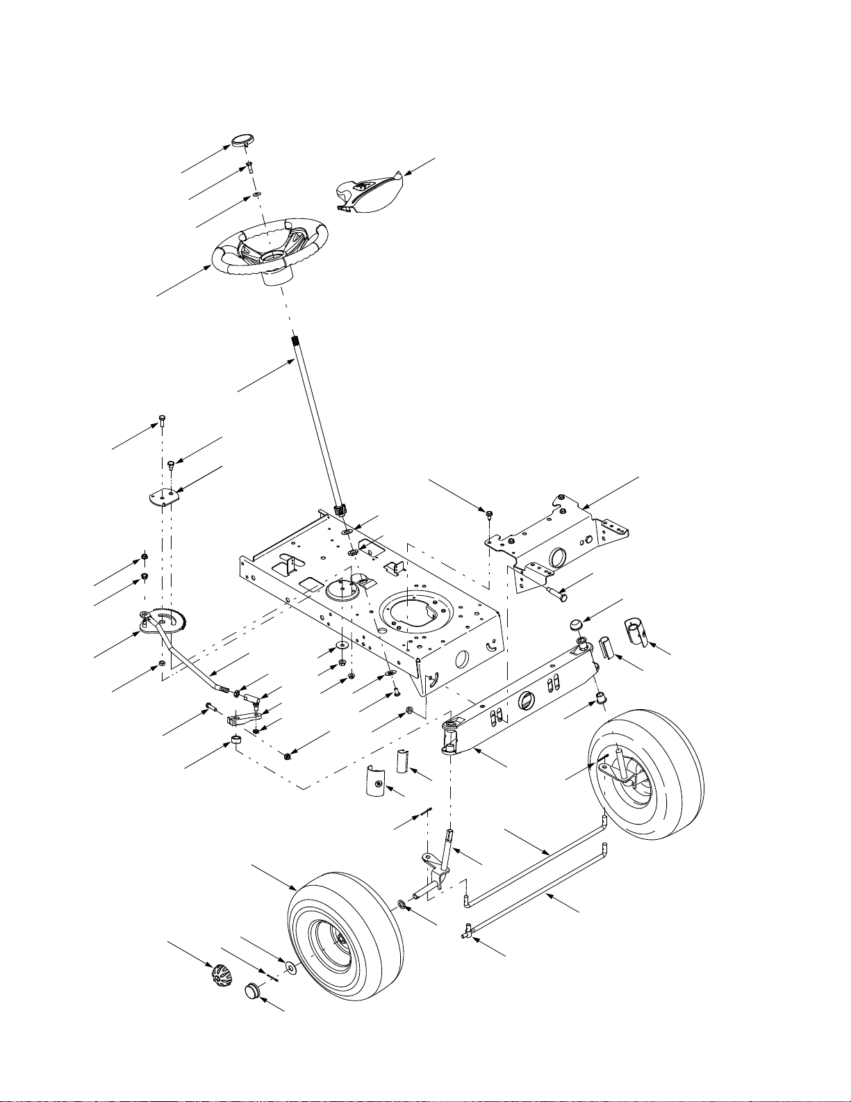
Models 660 – 688
REF.
NO.
PART
NO. DESCRIPTION
1 17198A Retainer Gear Segment Plate
2 683-0002A Pivot Bar, .625
3 710-0514 Hex Cap Screw, 3/8-16 x 1.0
4 710-0643 Hex Cap Screw, 5/16-18 x 1.0
5 710-0726 Self-tapping Scre w, 5/16-12 x .75
6 710-0805 Hex Cap Screw, 5/16-18 x 1.5
7 710-1309 Machine Screw, 5/16-18 x .75
8 712-0240 Jam Nut, 7/16-20 (Grade 2)
9 712-0262 Jam Nut, 3/8-24
10 712-0431 Flange Lock Nut, 3/8-16
11 712-3004A Flange Lock Nut, 5/16-18
12 714-0470 Cotter Pin, 1/8 x 1.25
13 717-1757A Stearing Segment Gear
14 723-0448A Ball Joint, 7/16 -20
15 726-0214 Push Cap, .625
16 731-04057A Axle End Cap, Standard
17 736-0187 Flat Washer, .64 x 1.24 x .060
18 731-2290A Deluxe Hub Cap
19 736-0242 Bell Washer, .34 x .872 x .060
20 736-0356 Bell Washer, .391 x .380 x .062
21 731-04039 Steering Wheel Cap, Small
731-04040 Steering Wheel Cap w/ Sprig, Small
22 738-0141 Shoulder Screw, .435 x .350, 5/16-18
23 738-0527 Shoulder Screw, .498 x 2.045
24 738-0919 Steering Shaft, 21.86
25 741-0475 Plastic Bushing, .38 ID
REF.
NO.
PART
NO. DESCRIPTION
26 741-0487A Flange Bushing, .632 ID
27 741-0656 Hex Flange Bearing, 5/8
28 747-04008 Tie Rod, Non-adjustable
29 747-1268B Steering Drag Link, 7/16-20
30 748-0389 Cap, 1.25 x .16
31 748-04014B Steering Arm
32 748-04020 Spacer, 1.0 x .645 x .56
33 750-0535 Spacer, .380 x .625 x .21
34 783-0041D Pivot Bar Bracket
35 631-04028 Steering Wheel, Three Spoke
631-04008 Steering Wheel, Three Spoke Soft Grip
36 731-04058 Axle End Cap, w/ Fitting
37 731-04064 Steering Wheel Cap, Large
731-04065 Steering Wheel Cap w/ Sprig, Large
38 634-0056A Round Shoulder Wheel Ass’y Complete
634-0105A Square Shoulder Wheel Ass’y Complete
634-0115 Square Shoulder Wheel Ass’y Complete
39 683-04016 RH Axle Assembly
683-04015 LH Axle Assembly
683-04014 RH Axle Ass’y (models with 46-in Deck)
683-04013 LH Axle Ass’y (models with 46-in Deck)
40 731-0484A Hub Cap
41 736-0162 Flat Washer, .64 x 1.0 x .12
42 736-0285 Flat Washer, .635 x 1.589 x .06
43 747-04057 Tie Rod, Adjustable
44 711-04059 Ferrule, 3/8-24 x .437 Dia
Wheel Ass’y
Complete
Round Shoulder 634-0056A 634-0172 741-0706
Square Shoulder 634-0105A 634-0172 741-0706
Square Shoulder 634-0115 634-0051 741-0569
Rim Assembly Inner Bearing Outer Bearing Tire Only Air Valve
(Flange w/ Fitting)
(Flange w/ Fitting)
(Ball Bearing)
741-0487A
(Plastic Flange)
741-0487A
(Plastic Flange)
741-0569
(Ball Bearing)
734-0864
(15 x 6 x 6)
734-1731
(15 x 6 x 6)
734-1731
(15 x 6 x 6)
734-0255
734-0255
734-0255
Round ShoulderSquare Shoulder
NOTE: Tractor features vary by model. NOT all parts listed above and pictured on the previous page are standard equipment.
9
Page 10

Model
s 660 – 688
40
44
41
42
43
14
Models with Knob-adjust Seat
39
38
9
8
10
7
10
4
29
11*
2
16
20
28
45
Models with
Quick-adjust Seat
46
47
19
5
21
35
15
18
30
6
3
12
1
6
23
29
27
23
4
25
24
26
31**
53
32**
19
**
48
49
50
51
52
33
22
36
37
34
13
17
19**
31**
32**
8
1
18
* Attach the short end of spring to the notch in the rear
of Ref. No. 2. Attach the long end to Ref. No. 1.
** Shown in orientation for 38-inch deck. Found on tractor
models with 38- or 42-inch deck only.
10
7
1
Page 11

Models 660 – 688
REF.
NO.
1 17239C Seat Lift Bracket
2 17950A RH Pivot Support Bracket, Seat
3 17951A LH Pivot Support Bracket, Seat
4 710-0227 Self-tapping Scre w, #8-18 x .50
5 710-0726 Self-tapping Scre w, 5/16-12 x .75
6 712-0429 Lock Nut, 5/16-1 8
7 725-1303 Outer Seat Spring Switch
8 725-1439 Inner Seat Spring Switch
9 726-0278 Insulator Plate Boss
10 726-0279 Insulator Plate
11 732-0581B Extension Spring, .75 x 5.31
12 738-0296 Shoulder Screw, .437 x .286
13 17770H Running Board
14 17870C Fender
15 710-0751 Hex Screw, 1/4-20 x .620
16 710-1208 Self-tapping Screw, 5/16-18 x 3.5
17 710-3008 Hex Screw, 5/16-18 x .75
18 712-0429 Nylon Lock Nut, 5/16-18
19 712-3027 Flange Lock Nut, 1/4-20
20 732-04038 Compression Spring, 1.314 x 1.8
21 750-04212 Spacer
22 783-04139A LH Running Board
23 710-0599 Self-tapping Screw, 1/4-20 x .5
24 725-1643 Spring Switch, Long
25 726-0320 Insulator Nut Plate
26 726-3054 U-Clip Nut, 1/4-20
27 783-04060A Shift Cover Panel, 6-speed
PART
NO. DESCRIPTION
783-04050A Shift Cover Panel, 8-speed
REF.
NO.
28 710-0870 Screw, 3/8-16 x .625
29 738-04012 Shoulder Screw, .625 x .175, 3/8-16
30 783-04081A Seat Pivot Bracket, Manual Adjust
31 710-0167 Carriage Screw, 1/4-20 x .50
32 761-0168B Blade Spindle Brake Assembly
33 723-04012 LH Abrasive Foot Pad
34 723-0422C RH Abrasive Foot Pad
35 735-04009 LH Rubber Foot Pad
36 735-0689A RH Rubber Foot Pad CORRECTED
37 726-3046
38
39
40 757-04021 Low Back Seat, Black
41 731-04074 Spacer
42 712-0137A Shoulder Screw, .340 x .285, 1/4- 20
43 783-0738A Seat Pivot Bracket, Quick-Adjust
44 736-0204 Flat Washer, .344 x .62
45 783-0753 Seat Select Bracket
46 783-0739 Seat Adjustment Lever
47 736-0175 Spring Washer
48 736-3019 Flat Washer, .531 x 1.062 x .134
49 738-0966 Shoulder Screw, .50 x .925, 3/8-16
50 783-0611 Seat Stop
51 710-1268 Screw, #10-16 x .375
52 732-0499 Compression Spring
53 720-0309A Grip
54 732-0735 Compression Spring, 1.314 x 2.55
PART
NO. DESCRIPTION
Ratchet Clip, .250 Dia
720-04009 Knob, 3/8-16 X .625
736-0219 Bell Washer, .389 x 1.120 x .030
757-04020 Medium Back Seat, Black
NOTE: Tractor features vary by model. NOT all parts listed above and pictured on the previous page are standard equipment.
11
Page 12

Model
s 660 – 688
12
13
71
40
40
13
54
40
57
35
72
24
67
82
27
34
37
10
2
15
36
30
69
41
19
33
35
70
9
75**
31
5
12
45
33
39
D
38
73
35
40
74
40
B
35
44
82
35
6
3
30
C
43
68
A
55
35
35
6
3
21
35
42
32
26
53
10
10
25
22
13
19
48
20
14
11
16
37
34
4
12
13
8
1
50
7
44
28
46
12
23
17
75**
58*
80***
8
61
79
* Attach the ends of springs (Ref. 58 & Ref.59)
to the notch openings in the rear of Ref. 25.
** Found on tractor models with 46-inch deck only.
*** Used on tractor models with Deluxe hub cap only.
76**
81
60
59*
C
56
‡
51
F
78**
77**
12
13
A
13
49
12
D
62
55
33
10
63
52
B
†
‡
E
7
18
66
Refer to
Refer to
†
29
64
†
E
on Page 18 & Page 20
‡
F
on Page 20
63
52
65
Page 13

Models 660 – 688
REF.
NO.
1 17668A RH Axle Support Bracket
2 17669A LH Axle Support Bracket
3 17962 Switch Plate
4 683-04025 Lift Handle Assembly
5 683-04049 Lift Shaft Assembly
6 710-0224 Self-tapping Screw, #10-16 x .5
7 710-0599 Self-tapping Screw, 1/4-20 x .5
8 710-0627 Hex Cap Screw, 5/16-24 x .75
9 710-0642 Self-tapping Screw, 1/4-20 x .75
10 710-0726 Self-tapping Screw, 5/16-12 x .75
11 710-3180 Hex Cap Screw, 5/16-18 x 1.75
12 710-3008 Hex Screw, 5/16-18 x .75
13 712-0429 Lock Nut, 5/16-18
14 712-3006 Hex Nut, 1/4-20
15 716-0106A E-Ring, .625 Dia Shaft
16 720-0233 Handle Grip
17 732-0369 Compression Spring, .55 x 1.37
18 732-0750A Switch Actuator Spring
19 736-0222 External Lock Washer, 1/4
20 736-0329 Lock Washer, 1/4
21 741-0487A Flange Bearing, .632 ID
22 747-04031 Battery Hold-down Rod
23 748-04011A Lift Shaft Connector
24 783-0345 Battery Tray
25 783-0355D Hitch Plate
26 783-04011A Lower Frame
27 783-04031 LH Upper Frame Side Panel
28 783-04032 RH Upper Frame Side Panel
29 783-04213 Deck Anti-sway Bracket
30 725-04039 Screw-mount Interlock Switch
31 683-04048A Stabilizer Shaft Assembly
32 711-04036 Ferrule, 1/2-20 x .50
33 711-04075A Ferrule, 3/8-24 x .375
34 712-0130 Lock Nut, 3/8-16
35 714-04023 Internal Cotter Pin, .080 x 1.56
36 732-04050A Extension Spring, 1.07 x 9.52
37 736-0219 Bell Washer, .389 x 1.12 x .030
38 736-0267 Flat Washer, .385 x .87 x .060
39 738-0322 Shoulder Bolt, .625 x .217
40 747-04018A Deck Hanger Link
41 747-04040A Deck Disengagement Rod
42 747-04069A Deck Hanger Link
43 747-04115A Stabilizer Rod (46-inch Decks)
PART
NO. DESCRIPTION
747-04157 Stabilizer Rod (38- and 42-inch Decks)
REF.
NO.
44 748-04307 Lift Link
45 783-04093 Stabilizer Bracket (46-inch Decks)
46 783-04113 Deck Lift Index Bracket
47 17630A Shift Lever Retainer
48 17840 Transaxle Mounting Bracket
49 17860 Pedal Mounting Bracket
50 725-1426 Solenoid
51 710-0176 Hex Cap Screw, 5/16-18 x 2.75
52 710-0809 Self-tapping Screw, 1/4-20 x 1.25
53 712-0271 Hex Sems Nut, 1/4-20
54 710-3015 Hex Screw ,1/4-20 x .75
55 714-0111 Cotter Pin, 1.0
56 732-04029 Extension Spring, .59 x 12.38
57 783-04059 Speed Select Lever
58 732-04075A Extension Spring, .73 x 12.54
59 732-04076 Extension Spring, 1.15 x 7.90
60 732-0722A Brake Return Spring
61 736-0242 Bell Washer, .34 x .872 x .060
62 747-04043 Variable Speed Control Rod
63 750-0566A Spacer, .260 x .372 x 1.030
64 683-04005A Clutch / Brake Pedal Assembly
65 735-0196 Foot Pad, 4.6
66 750-0802 Spacer, .640 x .76 x 2.63
67 720-04008 Shift Handle Grip
68 732-04017 Compression Spring, .89 x 1.75
69 736-0300 Flat Washer, .406 x .875 x .059
70 747-04039 Speed Control Rod
71 750-04080 Spacer, .640 x 1.0 x .78
72 725-1706A Battery, 270 CCA
73 712-3027 Flange Lock Nut, 1/4-20
74 711-0993 Belt Guard Pin, 1/4-20
75 749-0334 Spacer
76 710-1266 Hex Cap Screw, 5/16-18 x 3.25
77 710-0833 Hex Cap Screw, 5/16-18 x 5.25
78 748-04021A Shoulder Spacer
79 731-2290A Deluxe Hub Cap
80 736-0430 Flat Washer, .350 x 1.59 x .062
81 734-1675 Round Shoulder Wheel Ass’y Complete
82 748-04037 Spacer, .635 x 1.0 x .696
PART
NO. DESCRIPTION
783-04294 Stabilizer Bracket (38- and 42-inch Decks)
725-1737A Battery, 190 CCA
634-0104 Square Shoulder Wheel Ass’y Complete
Wheel Ass’y
Complete
Round Shoulder* 734-1675 634-0070 734-1596
Square Shoulder* 634-0104 634-0070 734-1730
NOTE: Tractor features vary by model. NOT all parts listed above and pictured on the previous page are standard equipment.
Rim Assembly Tire Only Air Valve
734-0255
(20 x 8 x 8)
734-0255
(20 x 8 x 8)
* See illustartion on Page 3
13
Page 14

Model
s 660 – 688
24
2
12
25
1
16
14
A
7
10
1
2
23
B
10
6
19
5
19
22
11
4
6
20
15
17
8
18
13
33
29
32
28
B
1
1
A
9
27
31
3
30
14
26
Page 15

Models 660 – 688
REF.
NO.
1 618-04034 Transmission, Single-speed
2 656-0059A Variable-speed Pulley, 4.75
3 683-04055A Torque Bracket
4 683-04056 Variable-speed Bracket
5 683-04057 Variable-speed Bracket
6 710-0514 Hex Cap Screw, 3/8-16 x 1.0
7 710-0606 Hex Cap Screw, 1/4-20 x 1.5
8 710-0627 Hex Cap Screw, 5/16-24 x .75
9 710-1260A Screw, 5/16-18 x .75
10 710-3015 Hex Screw ,1/4-20 x .75
11 712-0431 Flange Lock Nut, 3/8-16
12 712-0700 Flange Nut, 9/16-18
13 712-3027 Flange Lock Nut, 1/4-20
14 714-0209 Internal Cotter Pin, .125
15 718-04012 Bearing Cup
16 718-0758A Pulley Hub, 5/8 Spline
17 736-0362 Flat Washer, .320 x 1.25 x .06
18 720-04028 Shift Knob
19 738-0372B Shoulder Spacer, 1.0 x .38 x .38
20 741-0600 Ball Bearing, 17 x 40 x 12
21 747-04072 Shift Rod
22 750-04099 Stepped Spacer
23 754-04001A Lower Drive Belt
24 754-04002 Upper Drive Belt
25 756-04002 Transmission Pulley, 7.25
26 710-0599 Self-tapping Screw, 1/4-20 x .5
27 647-04019 Shift Lever Assembly
28 711-0736 Ferrule, 1/4-20 x 1.0
29 714-0104 Cotter Pin, 1.13
30 714-0470 Cotter Pin, 1.25
31 732-04067 Spring Compression Clip
32 736-0275 Flat Washer, .344 x .688 x .065
33 17630A Shift Lever Retainer
PART
NO. DESCRIPTION
NOTE: Tractor features vary by model. NOT all parts listed above and pictured on the previous page are standard equipment.
15
Page 16

Model
s 660 – 688
5
1
2
3
8
6
7
8
4
9
12
1
3
10
11
14
21
20
1
1
12
18
16
17
15
3
19
22
23
24
28
25
26
27
29
16
Page 17

Models 660 – 688
REF.
NO.
1 732-0614 Ring, Wire
2 716-0231 Ring, E Type, .750
3 736-0336 Flat Washer, 5/8 x 1.0 x .030*
4 736-0335 Washer, Thrust .635 x 1.26 x .06
5 710-1325 Self-tapping Screw, 1/4-20 x 1.625
6 719-04017 Upper Housing
7 711-1109 Input Shaft
8 741-0335 Needle Bearing, .625 x .813 x .495
9 717-1464 14-tooth Bevel Pinion
10 716-0108 Retaining Ring, .437
11 741-0340 Sleeve Bearing, .75 x .1.0 x 1.0
12 721-0338 Seal, .75 x 1.0 x .125
13 618-04041 Differential Assembly
14 741-0336 Flange Bearing, 5/8 x 3/4 x 3/4
15 717-1362 42-tooth Bevel Gear
16 717-1363 42-tooth Bevel Gear
17 718-0228 Clutch Collar
18 736-0519 Flat Washer, .70 x 1.125 x .031
19 711-04053 Drive Shaft
20 736-0495 Thrust Washer, 1.0 x .632 x .0
21 741-0337 Flange Bearing, 5/8 x 3/4 x 15/16
22 611-0011 Detent Shaft Assembly
23 741-0862 Detent Ball
24 732-0863 Compression Spring
25 719-04018 Lower Housing
26 717-0678 Brake Puck
27 761-0202 Brake Disc
28 710-1206 Self-tapping Screw, 1/4-20 x 2.375
29 661-0001 Brake Assembly
— 737-0148 Grease (19 oz.)
PART
NO. DESCRIPTION
736-0337 Flat Washer, 5/8 x 1.0 x .040*
736-0349 Flat Washer, 5/8 x 1.0 x .020*
*Use applicable flat washer (12a, 12b or 12c) in this application allowing .0150/.0020 in. end-play
NOTE: If rebuilding the upper housing, include two ounces (2 oz.) of Unirex® N3 grease (Part No. 737-0289) in the input shaft cavity .
17
Page 18

Model
s 660 – 688
3
14
19
18
13
23
20
11
16
10
11
(b)(c)
3
12
7
9
1
†
E
2
15
21
24
17
4
5
22
8
6
25
6
†
Refer to
8
†
E
on Page 12
18
Page 19

Models 660 – 688
REF.
NO.
1 618-0138A Spindle Assembly (a)
2 683-04003A Deck Shell (a)
3 710-0726 Self-tapping Screw, 5/16-12 x .75
4 710-1260A Screw, 5/16-18 x .75
5 710-1616A Self-tapping Screw, 5/16-18 x .75
6 712-0417A Hex Flange Nut, 5/8-18
7 714-04023 Internal Cotter Pin, .080 x 1.56
8 742-0610A Blade, 19.38” (a)
9 747-04018A Deck Hanger Link/Anti-sway Rod
10 754-0329A Deck Belt (a)
11 783-04148A Belt Cover (a)
12 783-04211 Anti-sway Stabilizer Bracket
13 712-0431 Flange Lock Nut, 3/8-16 (c)
14 734-0973 Deck Wheel, 5 x 1.38 (c)
15 738-0373 Shoulder Screw, .498 x 1.53 (c)
16 731-1032B Discharge Chute Assembly
17 710-0751 Hex Cap Screw:1/4-20 x .620
18 736-0270 Bell Washer , .265 x .75 x .062
19 712-3006 Hex Nut, 1/4-20
20 726-0233 Push Nut, 1/4
21 712-3087 Wing Nut, 1/4-20
22 710-0599 Self-tapping Screw, 1/4-20 x .5
23 710-0134 Carriage Screw, , 1/4-20 x .62
24 731-2363 Mulch Plug
25 783-1146A Deck Skirt (b) (c)
PART
NO. DESCRIPTION
618-0142A Spindle Assembly (b) (c)
683-04004A Deck Shell (b)
683-04035A Deck Shell (c)
742-0616A Blade, 21.23” (b) (c)
754-0371A Deck Belt (b) (c)
783-04149B Belt Cover (b) (c)
(a) Tractor models with 38-inch Deck Only
(b) Tractor models with 42-inch Deck Only
(c) Tractor models with 42-inch Deck w/ Deck Wheels Only
IMPORTANT:
For a proper
working machine, use
Factory Approved Parts.
V-belts are designed to
engage and disengage
safely. A substitute (non
OEM) V-belt can be
dangerous by not
disengaging completely.
NOTE: Tractor features vary by model. NOT all parts listed above and pictured on the previous page are standard equipment.
19
Page 20

Model
s 660 – 688
41
20
16
11
26
30
19
35
7
2
3
23
42
‡
F
12
22
8
27
25
1
4
39
19
30
26
36
16
28
9
34
1
40
G
6
21
G
7
43
16
3
39
3
38
37
4
29
24
47
46
41
13
45
17
20
48
31
44
18
33
†
E
7
10
5
15
15
9
2
3
†
Refer to
‡
Refer to
31
†
E
on Page 12
‡
F
on Page 12
Page 21

Models 660 – 688
REF.
NO.
1 17116 Deck Brake Assembly
2 17258D RH Belt Cover
3 618-0240A Spindle Assembly, 5.0 Dia.
4 683-04133 46-inch Deck Shell
5 710-0514 Hex Cap Screw, 3/8-16 x 1.0
6 710-0520 Hex Cap Screw, 1/4-20 x 1.5
7 710-0599 Self-tapping Screw, 1/4-20 x .5
8 726-0233 Push Nut, 1/4
9 710-1260A Screw, 5/16-18 x .75
10 710-3144 Hex Cap Screw, 3/8-16 x 2.0
11 710-3151 Hex Cap Screw, 5/8-18 x .875
12 731-1032 Discharge Chute Assembly
13 736-0173 Flat Washer, 28 X .74 X .063
14 712-0337 Hex Nut, 5/8-18
15 712-0417A Hex Flange Nut, 5/8-18
16 712-0431 Flange Lock Nut, 3/8-16
17 710-0751 Hex Cap Screw:1/4-20 x .620
18 714-04023 Internal Cotter Pin, .080 x 1.56
19 716-3020 Internal Retaining Ring
20 736-0270 Bell Washer, .265 x .75 x .062
21 731-1490 Slide Cap
22 732-04047 Extension Spring, .788 x 15.5
23 732-0594A Extension Spring, .91 x 7.33
24 734-0973 Deck Wheel, 5 x 1.38
PART
NO. DESCRIPTION
756-1187 Pulley Only
REF.
NO.
25 736-0158 Lock Washer, 5/8
26 736-0290 Flat Washer, 5/8
27 736-3088 Flat Washer, 1.585 x .635 x .062
28 738-0347 Shoulder Spacer, .625 x 1.16
29 738-0373 Shoulder Screw, .498 x 1.53
30 741-0524 Bearing, .625 x 1.574 x .470
31 742-0611A Three-in-one Blade, Star Center, 16.28"
32 742-0612A Three-in-one Blade, Star Center, 14.88"
33 747-04018A Deck Hanger Link/Anti-sway Rod
34 748-0234 Shoulder Spacer
35 750-0932A Spacer, .635 x .88 x 1.72
36 750-0960A Spacer, .635 x 1.25 x .445
37 754-0439 PTO Belt (Upper Deck Belt)
38 754-0440 Deck Belt (Lower Deck Belt)
39 756-0627B Idler Pulley, 3.5
40 756-0638 Double Pulley, 5.0
41 712-3006 Hex Nut, 1/4-20
42 783-0046 Idler Bracket
43 783-0063A LH Belt Cover
44 783-0141 Deck Skirt, Center
45 783-0142 Deck Skirt, Right-hand
46 710-0578 Screw, 1/4-20 x 1.5
47 731-1636 Mulch Plug
48 712-3087 Wing Nut, 1/4-20
PART
NO. DESCRIPTION
IMPORTANT:
For a proper
working machine, use
Factory Approved Parts.
V-belts are designed to
engage and disengage
safely. A substitute (non
OEM) V-belt can be
dangerous by not
disengaging completely.
NOTE: Tractor features vary by model. NOT all parts listed above and pictured on the previous page are standard equipment.
21
Page 22

Model
s 660 – 688
20
22
20
22
41
15
10
42
10
41
25
15
15
28
42
10
29
41
A
24
21
9
14
24
A
3
21
10
4
a
15
A.
B.
d
A
bc
A
11
12
34
A
3
2
13
25
17
10
15
30
41
A
8
12
5
16
1 16 1
a
7
37
6
38
2
27
16
3
e
31
1
4
36
35
33
e
43
c
1
17
12
5
18
17
16 1
b
39
40
5
26
27
12
5
26
16
A. Models with a 46-inch Deck
B. Models with a 38- or 42-inch Deck
d
19
12
5
26
22
Page 23

Models 660 – 688
REF.
NO.
1 710-0148 Screw, #8-32 x .375
2 710-0599 Self-tapping Screw, 1/4-20 x .5
3 710-0726 Self-tapping Screw, 5/16-12 x .75
4 710-1237 Screw, #10-32 x .625
5 710-1314A Socket Cap Screw, 5/16-18 x .625
6 710-1315 Self-tapping Screw, 3/8-16 x 1.25
7 751-0813 LH Exhaust Pipe
8 721-0460 Exhaust Gasket
9 726-0154 Push-mount Cable Tie, 7.5
10 726-0205 Hose Clamp, .490
11 726-0272 Clamp, 9/16
12 736-0119 Lock Washer, 5/16
13 751-0813 RH Exhaust Pipe
14 751B221535 Casing Clamp
15 751-0535 Fuel Line Hose
16 751-0564A Muffler Deflector
17 751-0616A Muffler, Twin Inlet
18 751-0650A RH Exhaust Pipe
19 751-0651A LH Exhaust Pipe
20 751-3140 Oil Drain Valve
21 751-3141 Oil Drain Hose
22 751-3142 Oil Drain Cap
23 783-0615C Muffler Heat Shield
24 783-0625C Engine Heat Shield
25 731-1682A Oil Drain Sleeve
26 751-0617A Muffer, Single Inlet
27 721-0208 Exhaust Gasket
28 737-0143 Oil Drain Cap, 3/8-18
29 737-0199 Oil Drain Pipe, 3/8-16 x 2.0
30 751B213146 Casing Clamp
31 751-0619A Exhaust Pipe
32 710-0227 Screw, #8-18 x .50
33 710-3029 Hex Screw, 7/16-20 x 1.25
34 711-1044 Belt Keeper Pin, 5/16 x 4.75
35 736-0171 Lock Washer, 7/16
36 736-0322 Flat Washer, .450 x 1.25 x .164
37 750-0956 Spacer, 1.0 x 1.4 x .825
38 756-04023 Engine Pulley, 3.12 x 5.56
39 721-0348 Exhaust Gasket
40 751-0620 Exhaust Pipe
41 712-0271 Hex Sems Nut, 1/4-20
42 725-0157 Cable Tie, 7.4”
43 751-0622 Exhaust Pipe
PART
NO. DESCRIPTION
(a) Tractor models with Tecumseh Twin-cylinder Engine
(b) Tractor models with Tecumseh Single-cylinder Engine (16 HP - 18 HP)
(c) Tractor models with Tecumseh Single-cylinder Engine (12 HP - 15 HP)
(d) Tractor models with Briggs and Stratton OHV Twin-cylinder Engine
(e) Tractor models with Briggs and Stratton OHV Single-cylinder Engine
NOTE: Tractor features vary by model. NOT all parts listed above and pictured on the previous page are standard equipment.
23
Page 24

Model
s 660 – 688
MTD LLC, P.O. BOX 361131 CLEVELAND, OHIO 44136-9722
24
 Loading...