

Page 1
OWNHrSGUW
$1.00
• ASSEMBLY
OPERATION • MAINTENANCE •
Made ^
in
AMERICA
WARNING: This unit is equipped with an internai combustion engine and should not be used
on or near any unimproved forest-covered, brush-covered or grass-covered land unless the
engine's exhaust system is equipped with a spark arrester meeting applicable local or state
laws (if any). If a spark arrester is used, it should be maintained in effective working order by
the operator.
In the State of California the above is required by law (Section 4442 of the California Public
Resources Code). Other states may have similar laws. Federal laws apply on federal lands.
A spark arrester for the muffler is available through your nearest engine authorized service
dealer or contact the service department, P.O. Box 368022, Cleveland, Ohio 44136-9722.
FORM NO. 770-8584J
Page 2
IMPORTANT
THIS SYMBOL POINTS OUT IMPORTANT SATETY INSTRUCTIONS WHICH, IF NOT FOLLOWED, COULD ENDANGER
THE PERSONAL SAFETY AND/OR PROPERTY DF YOURSELF AND OTHERS. READ AND FOLLOW ALL INSTRUCTIONS
A
IN THIS MANUAL BEFORE ATTEMPTING TO OPERATE YOUR POWER VACUUM. FAILURE TO COMPLY WITH THESE
INSTRUCTIONS MAY RESULT IN PERSONAL INJURY. WHEN YOU SEE THIS SYMBOL— ^ HEED ITS WARNING.
Your power vacuum was built to be operated according to the rules for safe operation in this manuai.
DANGER: As with any type of powi.>r equipment, careiessness or error on the part of the operator can resuit in
A
serious injury. If you viol: ite any of these rules, you may cause serious injury to yourseif or others.
RULES FOR SAFE OPERATION
Read this operating and service instruction manuei carefully.
Be thoroughly familiar with the controls and proper use of the
power vacuum.
Never allow children to operate this power vacuum.
Keep the area of operation clear of all persons, [ articulariy
small children and pets.
Check fuel before starting engine. Do not fill fuel tank indoors,
when engine is running, or while engine is hot. W pe off any
spilled fuel before starting engine.
Do not change engine governor settings.
Do not put hands near rotating parts for any reason.
If the power vacuum should start to vibrate abnormally, stop
the engine and check immediately for the cause. Vibration is
generally a warning of trouble.
Before cleaning, repairing or inspecting, make certa n all mov
ing parts have come to a complete stop. Disconnect spark plug
wire and keep wire away from plug to prevent accid mtal start
ing. Also keep throttle control lever in the stop positi )n.
If the power vacuum should become blocked with dr bris at any
point, shut engine off and wait until the impeller comes to a
complete stop before attempting to remove the obstruction.
Disconnect spark plug wire to prevent accidental stai ting.
10. Check all bolts for tightness at frequent periods.
11. Never store this power vacuum with fuel in the tank. Allow
engine to cool before storing in any enclosure.
12.
Keep bag and equipment free of debris when not in use.
13.
Never operate this power vacuum unless air duct and vacuum
bag are properly affixed in their place. Large zippered end of
bag must be closed when operating to prevent objects from
being blown out.
14.
Never empty vacuum bag when engine is running.
15.
Never change inlet nozzle or auxiliary hose attachment when
engine is running.
16. The manufacturer recommends that the operator wear safety
glasses or some other suitable eye protection when operating
this machine.
17.
Check the vacuum bag frequently for wear and replace when
necessary.
18.
Never operate as a leaf blower unless impeller guard and guard
assembly are properly affixed in their place.
Exercise caution whenever operating as a leaf blower. Do not
19.
allow discharge to be pointed in the direction of persons.
20.
No one should operate this unit while intoxicated or while tak
ing medication that impairs the senses or reactions.
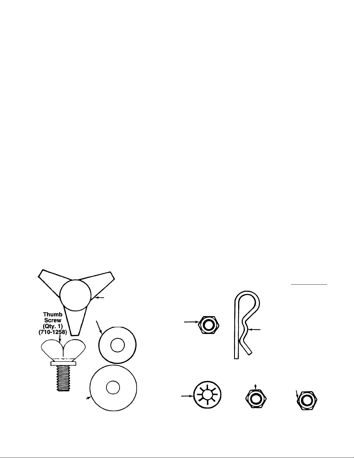
CONTENTS OF HARDWARE PACK
(Hardware pack may contain extra items which are not used on your unit. Quantities of parts and part
numbers are shown in parentheses.)
ATTACHING THE NOZZLE AND
AIR DUCT ASSEMBLY
Hand Knobs
(Qty. 2)
(720-0170)
Cupped
Washers (Qty. 3)
■ (736-0242)
ATTACHING THE
B
UPPER HANDLE
Hex Bolts 1/4-20 X
1-3/4" Long (Qty. 4)
(710-0136)
He c Lock Nuts
1A -20 Thread
(Qty. 4)
(712-0107)
INSTALLING THE BAG
m
t
ATTACHING THE CLUTCH ROD
(Self-Propelled Units Only)
Clutch Grip and Extension^____.
Spring are Not Shown ( )
Clevis Pin
(Qty. 1)
(711-0679)-
Hairpin Clip
(Qty. 1)
(714-0145)
Flat
Washer (Qty. 1)'
(736-0231)
I
I I I I I I I I I I I I I I I
0
INCHES
I
I I I
(E
Stu d Pins (Qty. 2)
(711-0737)
Push-On
S peed Nuts
(Qty. 2)
(1539-019)
Hex Lock
Nut 1/4-20 Thread
(Qty. 1)
(712-0107)
Hex Jam Nut
1/4-20 Thread
(Qty. 1)
(712-0298)
(Thinner Nut)
FIGURE 1.
Page 3
ASSEMBLY INSTRUCTIONS
V IMPORTANT: This unit Is shipped WITHOUT
GASOLINE or OIL. After assembly, service engine
with gasoiine and oii as instructed in the separate
engine manuai packed with your unit.
Upper
Nozzie
Handie^
Air
Duct
Assembiy
Directionai
Discharge
Assembiy
impeiier
Guard
Clutch
_____ Rod
(Self-Propelled
FiGURE 2.-Loose Parts in Carton
Models Only)
H
c—
FIGURE 3.—Optional Tow Bar Kit
Cupped
Washer^
NOTE: Reference to right or left hand side of the
vacuum is observed from behind the unit in the
operating position.
UNPACKING
Remove the vacuum, loose parts, hardware pack and
literature from the carton. Make certain all parts and
literature have been removed before the carton is dis
carded.
LOOSE PARTS IN CARTON
-{See Figure 2)
(1) Nozzle
(1) Upper Handle
(1) Air Duct Assembly
(1) Clutch Rod (Self-Propelled Models Only)
(1) Directional Discharge Assembly
(1) Impeller Guard
(1) Bag
TOW BAR KIT
Standard for push models, optional for self-pro
pelled models.
-(See Figure 3)
(2) Hex Bolts 5/16-18 x 1" Long
A
(2)
(4) Shoulder Spacers
B
(4)
C
D
E
F
G
H
1
Hex Nut 5/16-18 Thread
(2)
(1) Truss Machine Screw 1/4-20 x 3/4" Long
(1)
Lock Washer 1/4" I.D.
(1)
Hex Nut 1/4-20 Thread
(1)
(1) Shoulder Bolt
(1)
(2) Cupped Washers 3/8" I.D.
(2)
Hex Jam Lock Nut 3/8-16 Thread
(1)
(2) Tow Bar Halves (Not Shown)
(2)
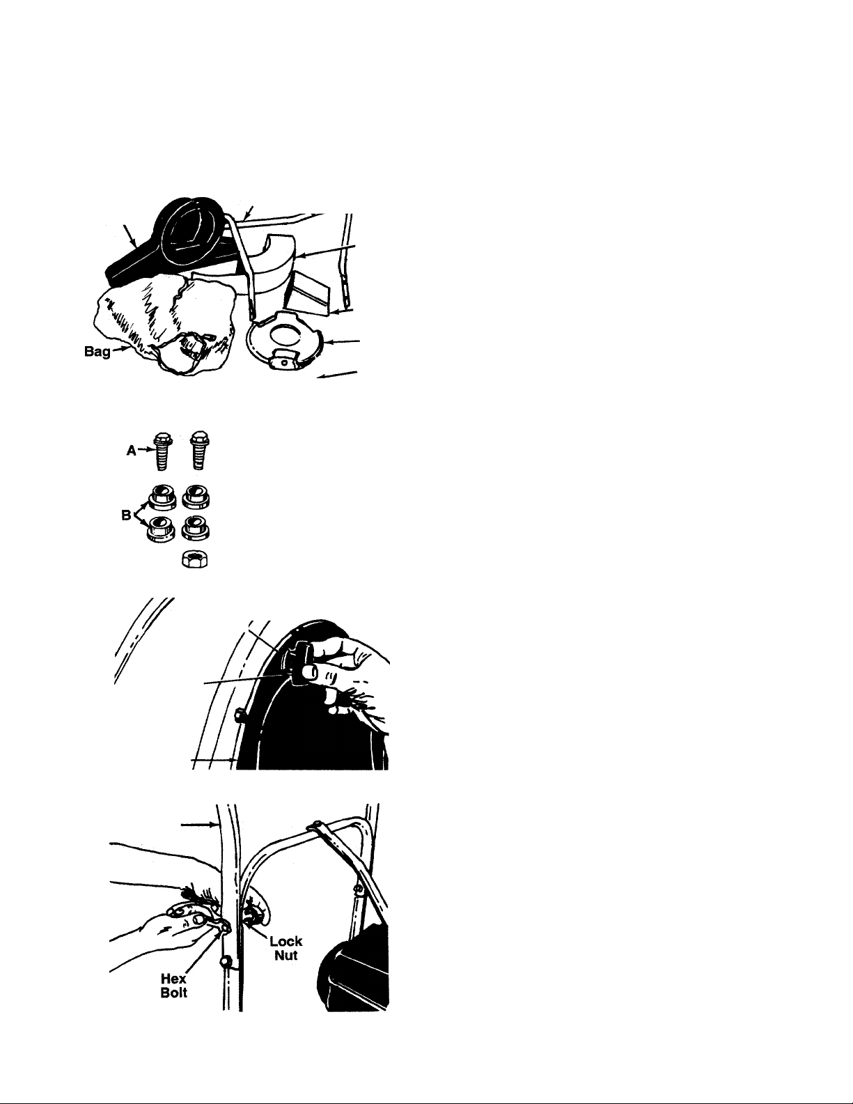
FIGURE 4.
Handle
FiGURE 5.
Nozzle
Upper
Hand
Knob
ATTACHING THE NOZZLE (Hardware A)
Place nozzle in position on front of housing so that it
rests in flanges. Secure with one hand knob and
cupped washer (cupped side of washer against the
-nozzle). See figure 4.
AHACHING THE UPPER HANDLE (Hardware B)
Place the upper handle in position over lower handle.
Fasten with four hex bolts and lock nuts provided.
-See figure 5. Two 7/16" wrenches are required.
Page 4
11
Hand
Knob
FIGURE 6.
Cupped
.Washer
Cup|)ed
Was tier
Thumb
Screw
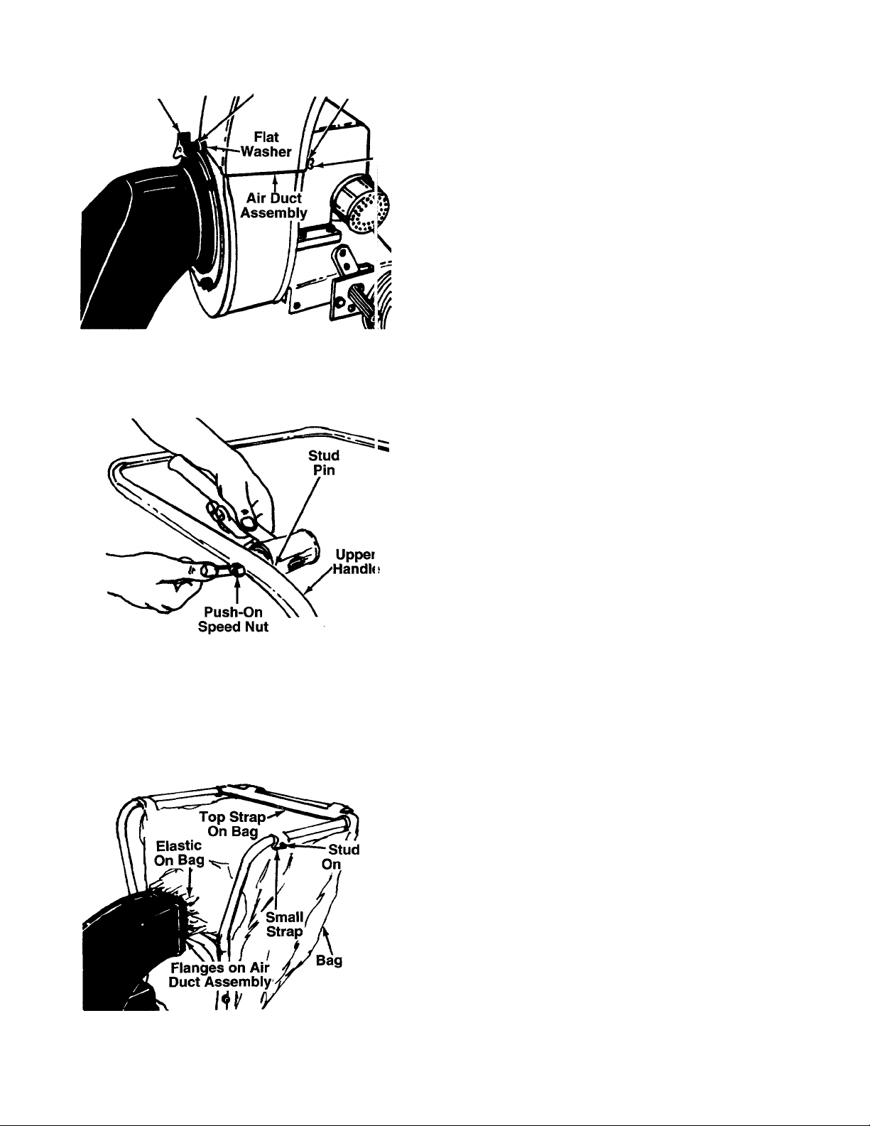
ATTACHING THE AIR DUCT ASSEMBLY (Hardware A)
Place air duct assembly over opening on top ot hous
ing. Secure front of air duct assembly with one flat
washer, cupped washer (cupped side of washer
against flat washer) and a hand knob. Secure back
(close to engine) with one cupped washer (cupped
side against air duct assembly) and thumb screw. See
-figure 6.
FIGURE 7.
Pin
Handle
INSTALLING THE BAG (Hardware C)
1. Place the stud pins in holes in upper handle
(head of pins go to the inside of handle). Secure
pins with push-on speed nuts by holding speed
nut with box wrench and tapping pin with ham-
--------
mer. See figure 7.
2. Assemble the bag by slipping the top straps on
bag over upper handle. Hook two small straps
over stud pins on handle. Slip elastic opening of
bag over air duct assembly. Be certain elastic on
bag is placed over the flanges on air duct assem-
— bly. See figure 8.
FIGURE 8.
Page 5

*\
FIGURE 10.
Rod
AHACHING THE CLUTCH ROD (Hardware D)
(Self-Propelled Models Only)
1. Assemble the clutch grip to the left hand side of
upper handle. Secure in place with clevis pin and
---------
hairpin clip. See figure 9. Head of clevis pin
should be to the outside of handle.
2. Slide the extension spring onto clutch rod as
— shown in figure 10. Thread hex lock nut onto
clutch rod approximately 2-1/2 inches.
N
■N
Clutch Bracket
Assembly
FIGURE 11.
FIGURE 12.
Hand
Knob
3. Hook top (hooked end) of clutch rod into upper
hole on clutch grip. See figure 9. Hook spring into
— clutch bracket assembly. See figure 11. Adjust
nut on the clutch rod so that when the clutch grip
is all the way up, there is no slack in the spring.
4. Thread hex jam nut (thinner nut) onto clutch rod,
and lock it against the lock nut.
CONVERTING VACUUM TO A LEAF BLOWER
WARNING: Be sure to stop engine and
A
1. Remove the bag. Remove the air duct assembly
3.
disconnect spark plug wire.
by removing the hand knob, cupped washer and
flat washer from the front of the air duct assem
bly, and the thumb screw and cupped washer
from behind the air duct assembly. Refer to figure
6.
Remove the nozzle by removing one hand knob
and cupped washer. Refer to figure 4.
Remove the hand knob and cupped washer
■which hold the housing to engine brace. See fig
ure 12.
Page 6

Cupp^ Washen
Flat Washer
I I
4. Lift up and out on the housing and rotate it 105°
clockwise. Chute opening should be to the right
hand side when viewed from the front of unit. See
— figure 13.
5. Place the impeller guard into flanges on front of
housing. Line up hole in guard with hole on hous
ing. Secure with one hand knob and cupped
washer (cupped side of washer against the
impeller guard). See figure 13.
Place the directional discharge assembly over
chute opening. Secure with one hand knob,
cupped washer and flat washer, and the thumb
screw and cupped washer. The cupped side of
washer goes against the flat washer. See figure
14.
Hand Knob
FIGURE 14.
Truss
Machine
Hex Nut
(C)
Screw (D),
Hex
Bolt (A)
Shouider
Spacers (B)
Lock
Washer (E) yt ■
FiGURE 15.—Optionai Tow Bar
Direc’ional
Disci large
Assembly
Cupped
Washer (H)
^^Shouider
Nut (F) Bon (Q)
Waiiher (H)
INSTALLATION OF OPTIONAL TOW BAR
1. Remove the self-tapping screws on each side of
frame. Refer to illustration on page 10, reference
number 42.
2. Place one bar half in position on frame of vacu
um. Place one shoulder spacer (B) between
frame and tow bar. Next, place shoulder spacer
(B) and hex bolt (A) through tow bar and frame.
--------
Secure with hex nut (C). See figure 15. Repeat
on other side.
3. Secure the two tow bar ends together with truss
machine screw (D), lock washer (E) and hex nut
(F). See figure 15.
To attach the tow bar to a hitch, place the shoulder
bolt (G) up through the tow bar. Place one cupped
washer (H) on the shoulder bolt, then the hitch plate
Clipped
and the other cupped washer. Cupped side of the
washers must be against the hitch plate. Secure with
hex jam lock nut (I). See figure 15.
OPERATION
BEFORE STARTING ENGINE
Service engine with gas and oil. See engine manual
packed with vacuum for complete instructions for care
and maintenance of engine. Read directions c irefully.
WARNING: Revolving blades -- keep
▲
hands away from all openings.
TO START ENGINE
After the engine has been properly fueled and oiled
(refer to engine operating and maintenance instruc
tions), start engine as follows.
1. Move choke lever on engine to CHOKE position.
(A warm engine may not require choking.)
2. Move throttle control lever on engine to FAST
position.
Page 7

3. Grasp starter handle and pull rope out slowly until
engine reaches start of compression cycle (rope
N
will pull slightly harder at this point). Let the rope
rewind slowly.
4. Pull rope with a rapid, continuous, full arm stroke.
Keep a firm grip on starter handle. Let rope
rewind slowly. Do not let starter handle snap back
against starter.
5. Repeat instructions 3 and 4 until engine fires.
When engine starts, move choke control gradual
ly to RUN position.
6. Self-Propelled Models Only—To engage the
drive mechanism, squeeze the clutch grip against
the upper handle. Release the clutch grip to stop
the forward motion.
TO STOP ENGINE
1. To stop engine, move throttle control lever to OFF
position.
2. Disconnect spark plug wire and ground to prevent
accidental starting while equipment is unattended.
IMPORTANT: The vacuum bag may have an air
escape located on the upper right hand side. See
figure 16. The air escape can be opened if the
vacuum is operated in wet, sandy or muddy
conditions.
The bag may be emptied using the large zipper as
shown in figure 16. Be certain the zipper is closed
when operating the unit.
FIGURE 16
ADJUSTMENTS
WARNING: Do not at any time make any
adjustment to the unit without first stop
A
HEIGHT ADJUSTMENT
The height adjustment crank is located on the right
hand side of the vacuum. See figure 17. Turn the
crank clockwise to raise the nozzle. Turn the crank
counterclockwise to lower.
FIGURE 17.
ping engine and disconnecting spark
piug wire.
CARBURETOR ADJUSTMENT
WARNING: If any adjustments are made
to the engine while the engine is running
A
Minor carburetor adjustment may be required to com
pensate for differences in fuel, temperature, altitude
or load.
NOTE: A dirty air cleaner will cause engine to run
rough. Be certain air cleaner is clean and attached to
the carburetor before adjusting carburetor.
Do not make unnecessary adjustments. Factory set
tings are satisfactory for most applications and condi
tions. If adjustment is needed, refer to the separate
engine manual packed with your vacuum.
(e.g. carburetor), keep clear of all moving
parts. Be careful of heated surfaces and
muffler.
CLUTCH ROD ADJUSTMENT
(Self-Propelled Models Only)
To adjust the clutch rod, refer to step numbers 3 and
4 under “Attaching the Clutch Rod” in Assembly
Instructions.
A
MAINTENANCE
WARNING: Always stop engine and dis
connect spark plug wire before cleaning,
lubricating or performing any repairs or
maintenance.
LUBRICATION
Wheels—Rear wheels are provided with light oil bear
ings. Place a few drops of SAE 30 oil on each bearing
once a season.
Page 8

Gear Box (Self-Propelled Models Only)—The gear
box is lubricated with 3 ounces of High Tenp. (450°
F.) grease. Order part number 737-0223. Pf riodically
check lubricant level by removing the two se f-tapping
screws on the gear box cover and lifting off t ie cover.
Do not change grease; simply add if necessary.
ENGINE
Refer to the separate engine manual fo' engine
maintenance instructions.
Maintain engine oil as instructed in the ¡separate
engine manual packed with your unit. Read and follow
instructions carefully.
Service air cleaner every 25 hours under noi mal con
ditions. Clean every few hours under extremely dusty
conditions. Poor engine performance and flooding
usually indicates that the air cleaner should be ser
viced. To service the air cleaner, refer to the separate
engine manual packed with your unit.
The spark plug should be cleaned and the gap reset
once a season. Spark plug replacement i;; recom
mended at the start of each season; chec< engine
manual for correct plug type and gap specific itions.
Clean the engine regularly with a cloth or brush. Keep
the cooling system (blower housing area) clean to
permit proper air circulation which is essential to
engine performance and life. Be certain to re ¡move all
dirt and combustible debris from muffler area
BELT REPLACEMENT (Self-Propelled Models Only)
1. Remove the nozzle or impeller guard from front of
blower housing.
2. Remove hex bolt and lock washer from center of
impeller. See figure 18. A 9/16" socket wrench
with extension is needed.
11
FIGURE 19.
5. Slide belt off the impeller pulley. Slide housing
and impeller off engine crankshaft. Be careful to
not lose square key. See figure 20.
Engine
Crankshaft
P.T.O.
Pulley Square
Key
FIGURE 20.
6. Slide impeller and blower housing assemblies off
crankshaft.
7. Remove belt from P.T.O. pulley and install new
belt. See figure 20.
3.4.Remove hand knob and cupped washer from top
of housing.
Remove two self-tapping screws which hold the
belt guard. See figure 19. A 3/8” wench is
required. Lift off belt guard.
NOTE: When reassembling the new belt, the aid of
another person will be helpful.
8. Turn the crankshaft until the keyway on shaft is
directly on top. While holding housing assembly
and impeller assembly, line up the keyway on the
pulley with the key on the crankshaft, and slide
housing and impeller assemblies onto crankshaft.
9. Secure impeller to crankshaft with hex bolt and
lock washer, removed in step 2. Tighten securely.
10. Slip belt over impeller pulley. Reassemble the
belt guard.
11. Secure blower housing with hand knob and wash
er.
12. Reassembie the nozzle or impeller guard.
Page 9

OFF-SEASON STORAGE
The following steps should be taken to prepare your
N
vacuum for storage.
1. Clean and lubricate the vacuum thoroughly as
described in the lubrication instructions.
2. Refer to engine manual for correct engine storage
instructions.
3. If storing in an unventilated or metal storage
shed, coat metal parts with a light oil or silicone to
prevent rust.
4. Store in a dry, clean area. Do not store next to
corrosive materials, such as fertilizer.
OPTIONAL EQUIPMENT^
Hose
Attachment
Kit
Hose Attachment Kit Model 290-204-000 is available
as optional equipment. See figure 21.
TROUBLE SHOOTING
PROBLEM
Engine fails to start
Loss of power;
operation erratic
Engine overheats
Too much vibration
POSSIBLE CAUSE(S)
1. Fuel tank empty, or stale fuel.
2. Spark plug wire disconnected.
3. Faulty spark plug.
1. Spark plug wire loose.
2. Unit running on CHOKE.
3. Blocked fuel line (if so equipped)
or stale fuel.
4. Water or dirt in fuel system.
5. Carburetor out of adjustment.
6. Dirty air cleaner.
1. Carburetor not adjusted
properly.
2. Engine oil level low.
Loose parts or damaged
crankshaft.
FIGURE 21.
CORRECTIVE ACTION
1. Fill tank with clean, fresh fuel.
2. Connect wire to spark plug.
3. Clean, adjust gap or replace.
1. Connect and tighten spark plug wire.
2. Move choke lever to OFF position.
3. Clean fuel line; fill tank with clean
fresh gasoline.
4. Disconnect fuel line at carburetor to drain fuel
tank. Refill with fresh fuel.
5. Adjust carburetor.f
6. Service air cleaner.t
1. Adjust carburetor.f
2. Fill crankcase with proper oil.
Stop engine immediately and disconnect
spark plug wire. Tighten all bolts and nuts.
Make all necessary repairs. If vibration continues,
have unit serviced by an authorized service
dealer.
Unit does not
discharge
tRefer to the engine manual packed with your unit.
NOTE: For repairs beyond the minor adjustments listed above, please contact your nearest authorized service dealer.
1. Directional discharge or
nozzle clogged.
2. Foreign object or dirt lodged in
air vane plate assembly.
3. Vacuum bag is full.
4. Belt worn and/or stretched.
1. Stop engine immediately and disconnect
spark plug wire. Clean directional discharge
or nozzle.
2. Stop engine immediately and disconnect
spark plug wire. Remove lodged object or dirt.
3. Empty bag.
4. Replace belt. See maintenance section of
this manual.
Page 10

11
Page 11

N
Page 12

11
For Replacement Parts, Contact:
SERVICE DEPARTMENT • P.O. BOX 368022 • CLEVELAND, OHIO 44136-9722
 Loading...