

Page 1
N
OWNBrS GUIDE
• ASSEMBLY • OPERATION • MAINTENANCE •
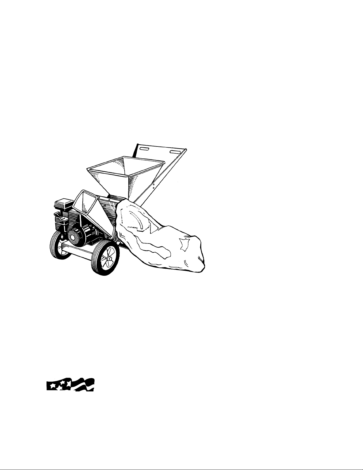
5 and 8 H.P.
SHREDDERS
Model Series
N
Important:
645B thru 651B
IMPORTANT!
Record the Model No. and Mfg. Code which
appear on your unit in the space below. You
must have these numbers, along with the date
of purchase, in order to receive warranty or ser
vice.
MEETS ANSI SAFETY STANDARDS
MODEL NO. MFG. CODE
Read Safety Rules
and Instructions Carefully
WARNING: This unit is equipped with an internal combustion engine and should not be used
on or near any unimproved forest-covered, brush-covered or grass-covered land unless the
engine’s exhaust system is equipped with a spark arrester meeting applicable local or state
laws (if any). If a spark arrester is used, it should be maintained in effective working order by
the operator.
In the State of California the above is required by law (Section 4442 of the California Public
Made ”
in
AMERICA
Resources Code). Other states may have similar laws. Federal laws apply on federal lands.
A spark arrester for the muffler is available through your nearest engine authorized service
dealer or contact the service department, P.O. Box 360900, Cleveland, Ohio 44136.
FORM NO. 770-8582J
Page 2

A
S/kFETY RULES
WARNING: TO REDUCE THE POTENTIAL FOR ANY INJURY, COMPLY WITH THE FOLLOWING SAFETY INSTRUCTIONS. FAILURE TO COMPLY WITH THE INSTRUCTIONS MAY RESULT IN PERSONAL INJURY.
TRAINING
• Read this owner’s manual carefully in its entirety before
attempting to assemble or operate this machine Be com
pletely familiar with the controls and the propar use of
this machine before operating it. Keep this manual in a
safe place for future and regular reference and dr order
ing replacement parts.
• Children must never be allowed to operate this equip
ment.
• No one should operate this unit while intoxicated or while
taking medication that impairs the senses or reactions.
• This equipment should never be operated in the vicinity
of children, pets or other persons.
• Never run your machine in an enclosed area as the
exhaust from the engine contains carbon monoxide, which
is an odorless, tasteless and deadly poisonous g; is.
• Never place your hands or any part of your body or cloth
ing inside the feeding chamber, discharge chute, or near
any moving part while the machine or engine is lunning.
• If it is necessary for any reason to inspect or lepair the
feeding chamber or any part of the machine whe e a mov
ing part can come in contact with your body ot clothing,
stop the machine, allow it to cool, disconnect he spark
plug wire from the spark plug and move it away from the
spark plug before attempting such inspection or rspair.
PREPARATION
• Wear safety glasses provided with your unit whi e operat
ing the shredder to prevent injury from any mate dal which
may be ejected out of the openings.
• Wear proper apparel. Avoid wearing loose fittinc clothing.
Wear gloves when handling material.
• HANDLE GASOLINE WITH CARE as it is an extremely
flammable fuel.
• Check the fuel before starting the engine. Do r ot fill the
fuel tank indoors, while the engine is running, or while the
engine is still hot. Turn the unit off and let the ergine cool
before refueling.
• Fuel your shredder in a clean area. Do not smoke while
refueling.
• Fuel tank cap must be secure at all times except during
refueling.
• Avoid spilling gasoline or oil. Wipe the unit clean of any
spilled fuel or oil.
• Store fuel and oil in approved containers, away from heat
or open flame, and out of reach of children.
• This machine should be operated only upon a le/el sur
face.
• Assure that all screws, nuts and bolts and other asteners
are properly secured.
OPERATION
• When feeding shreddable material into this eijuipment,
be extremely careful that pieces of metal, rock s, bottles,
cans or other foreign objects are not included. Personal
injury or damage to the machine could result.
If the cutting mechanism strikes any foreign object or if
your machine should start making an unusual noise or
vibration, immediately stop the engine, disconnect the
spark plug wire from the spark plug and move it away
from the spark plug. Allow the machine to stop and take
the following steps:
Inspect for damage.
Replace or repair any damaged parts.
Check for any loose parts and tighten to assure continued
safe operation.
The engine must be kept clean of debris and other accu
mulations.
Do not allow an accumulation of processed material to
build up in the discharge area as this will prevent proper
discharge and can result in kick-back from feed opening.
Never place your hands or any other part of your body or
clothing inside the feeding chamber, discharge chute or
near any moving part while the engine is running.
Keep all guards and deflectors in place and in good work
ing condition to assure continued safe operation.
Always stand clear of the discharge area when operating
this machine.
Keep your face and body back from the feed opening to
avoid accidental bounce back of any material.
Do not over-reach. Keep proper balance and footing at all
times.
The engine governor settings on your machine must not
be altered, changed, or tampered with. The governor
controls the maximum safe operating speeds and pro
tects the engine and all moving parts from damage
caused by overspeed.
Do not transport machine while engine is running.
Do not operate engine if air cleaner or cover directly over
carburetor air intake is removed, except for adjustment.
Removal of such parts could create a fire hazard.
MAINTENANCE AND STORAGE
• When this equipment is stopped for servicing, inspection,
storage or to change an accessory, make sure the spark
plug wire is disconnected from the spark plug and moved
away from the spark plug. The machine should be
allowed to cool down before making such inspection,
adjustments, service, etc. Maintain your machine with
care and keep it clean for the best and continued safe
operation.
• Do not use flammable solutions to clean the air filter.
• When not in use, your machine should be stored out of
the reach of children. Keep where gasoline fumes will not
reach an open flame or spark. For long periods of stor
age, refer to the “Off-Season Storage” section of this
manual.
Page 3
ASSEMBLY INSTRUCTIONS
cc
-5/16-18x8-3/8" Long
N
ATTACHING THE LOWER lA
LEAF RAMP SECTION
Hex Bolt
Washer ( f ) )
5/16" I.D.
Hex Lock
Nut 5/16-18
Thread
IMPORTANT: This unit is shipped WITHOUT
GASOLINE or OIL. After assembly, see separate
engine manual for proper fuel and engine oil rec
ommendations.
NOTE: To determine right and left hand sides of your
shredder, stand behind and face the hopper (engine
is at the front of the unit).
Your shredder has been completely assembled at the
factory, except for the hopper, lower and upper leaf
ramp sections, chute deflector and the catcher bag.
The hardware pack and safety glasses are also
included in the carton.
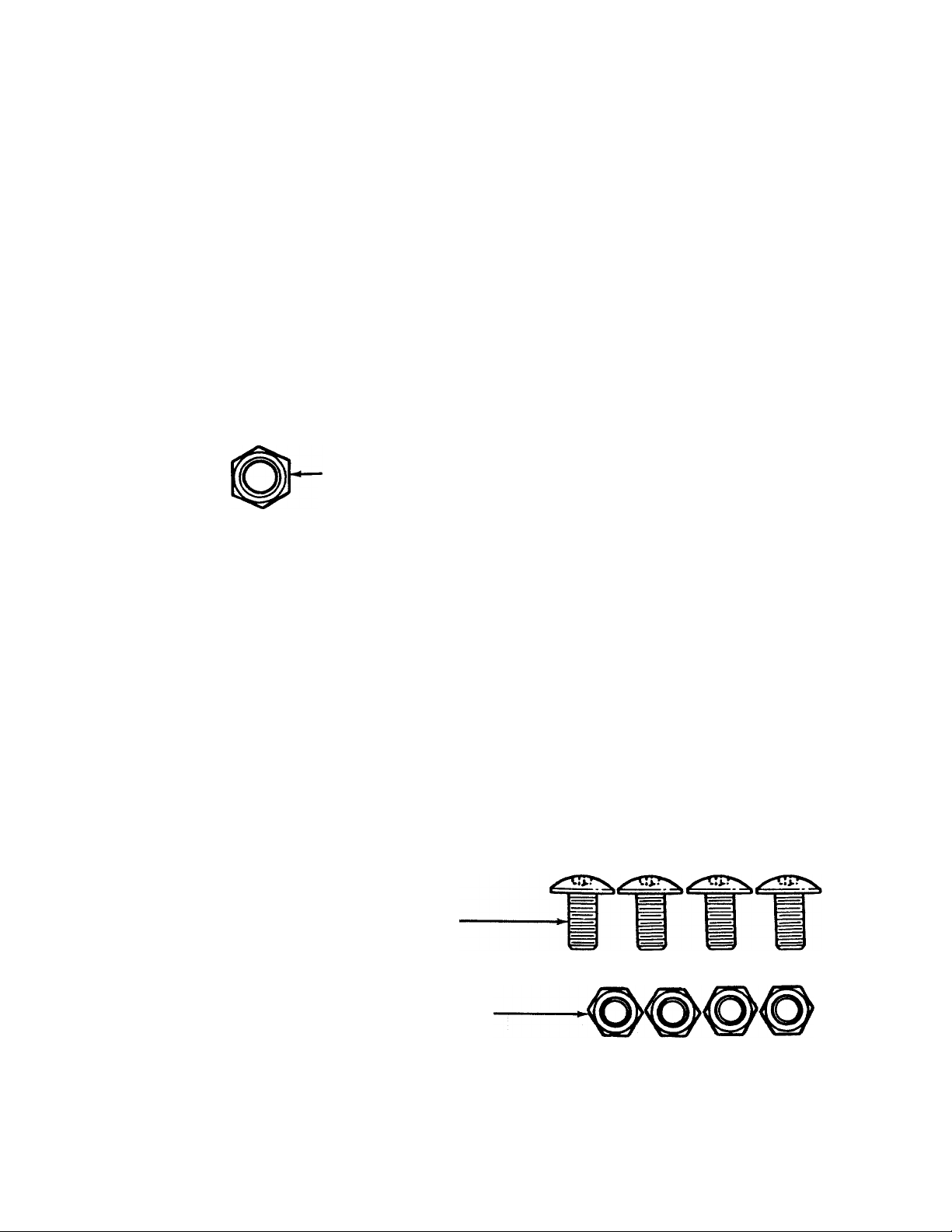
The hardware pack contains the parts shown in figure
1 (shown full size).
TO REMOVE SHREDDER FROM CARTON
Cut the corners of the carton. Remove all packing
inserts. Roll shredder out of carton. Make certain all
parts and literature have been removed before the
carton is discarded.
TOOLS REQUIRED FOR ASSEMBLY
(1) Phillips Screwdriver
(2) 1/2" Wrenches (one must be a socket wrench)
(2) 7/16" Wrenches or Adjustable Wrenches
FIGURE 1.
B
AHACHING THE UPPER LEAF RAMP SECTION
Truss Machine
Screws 1/4-20 x 1/2"
Long
Hex Lock Nuts
1/4-20 Thread
Page 4
11
FIGURE 2.
Hou sing
Asse mbly
Hex Bolt
Chute
[ leflector
WARNING: Make certain the spark plug
wire is disconnected and moved away
A
AHACHING THE CHUTE DEFLECTOR
(See Figure 2)
■ 1. Remove the hand knobs and cupped washers
2. Remove the hex lock nut, two spacers and hex
3.
4.
5.
A
from the spark plug before assembling
the shredder.
from each side of the discharge opening on the
left side of the shredder.
bolt from inside the hinge on the housing assem
bly. Do not remove one spacer from the hex bolt.
Place the chute deflector in position on the dis
charge opening on the left side of the shredder.
Insert hex bolt and spacer through hinge on chute
deflector and housing (spacer fits inside of hinge).
Place the second spacer over the hex bolt, inside
the other part of the hinge. Secure with hex lock
nut. Tighten securely.
Secure both sides of the chute deflector to the
housing using the hand knobs and cupped wash
ers (cupped side of washers go against the chute
deflector).
WARNING: Do not operate this chipper-
shredder unless the chute deflector has
been properly Installed and Is secured
with the hand knobs.
Hopper
Self-Tapping
Screws
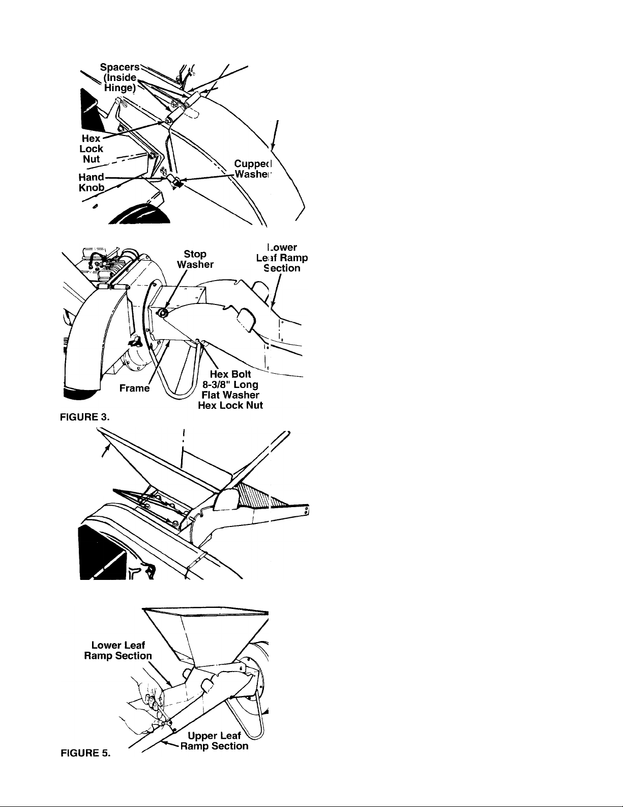
FIGURE 4.
-ATTACHING THE LOWER LEAF RAMP SECTION
(Hardware A)
Insert hex bolt 8-3/8" long through lower leaf ramp
section and frame. Secure with flat washer 5/16" I.D.
and hex lock nut. Make certain the edges of the lower
leaf ramp section are underneath the stop washers.
See figure 3. Plastic insert in hex nut should face
away from lower leaf ramp section. Tighten hex nut
until parts are snug, but so lower leaf ramp section
can still be rotated on the frame.
AHACHING THE HOPPER
When attaching the hopper, first remove the five self
tapping screws from the frame of the unit. Place the
-hopper in position on the shredder. See figure 4. Start
all five self-tapping screws, then tighten securely
using a 1/2" socket wrench.
ATTACHING THE UPPER LEAF RAMP SECTION (Hardware B)
Place the edge of upper leaf ramp section inside the
lower leaf ramp section. Secure with four truss
machine screws and hex lock nuts. The heads of the
truss machine screws should be to the inside of the
upper leaf ramp section. Start all screws and nuts,
-then tighten securely. See figure 5.
Page 5

ATTACHING THE CATCHER BAG
Your shredder is equipped with a catcher bag to catch
the shredded material.
To attach the bag, place the opening of the bag over
the chute deflector so it completely covers the chute
opening. Depress the plunger on the drawstring, pull
on the drawstring until the bag is tight around the
chute opening. Release plunger to lock it into position.
'See figure 6.
OPERATION
KNOW YOUR SHREDDER
READ THIS OWNER’S MANUAL AND SAFETY RULES BEFORE OPERATING YOUR SHREDDER. Compare
the illustrations with your shredder to familiarize yourself with the location of various controls and adjustments.
Save this manual for future reference.
OPERATING CONTROLS (See figure 7)
RELEASE BAR—Used to release the leaf ramp when
raising or lowering.
CHOKE LEVER—Used to enrich the fuel mixture in
the carburetor when starting a cold engine.
N
STARTER HANDLE—Used to manually start the
engine.
THROTTLE CONTROL—Controls engine speed and
stops the engine.
The operation of any shredder can resuit in for
eign objects being thrown into the eyes, which
can resuit in severe eye damage.
Aiways wear safety glasses or eye
yj shields. We recommend wide
^ vision safety mask for over specta
cles or standard safety glasses.
Page 6

11
BEFORE STARTING
1. Place the shredder on a firm, level surface.
2. Attach spark plug wire to spark plug.
3. Service engine with gasoline and oil as instructed
in the separate engine manual packed w ith your
shredder.
4. 8 H.P. Briggs & Stratton engine only: Open
fuel shut-off valve.
NOTE; Check the fuel level periodically to a\, old run
ning out of gasoline while operating the c hippershredder. If the unit runs out of gas as it is si 'redding
or chipping, it may be necessary to unclog the unit
before it can be restarted. Refer to “Remo ving the
Flail Screen” on page 8.
TO START ENGINE
WARNING: Be sure no one other t lan the
operator is standing near the st redder
A
1. Place the throttle control lever In FAST ¡losition.
2. Move choke lever to CHOKE position (a warm
3. Grasp starter handle (see figure 8) and pull rope
4. Pull rope with a rapid, continuous, full arm stroke.
5. Repeat preceding instructions 3 and 4 until
whiie starting or operating.
See figure 8.
engine may not require choking).
out slowly until engine reaches start of compres
sion cycle (rope will pull slightly harder at this
point). Let the rope rewind slowly.
Keep a firm grip on starter handle. L at rope
rewind slowly. Do not let starter handle sn ap back
against starter.
engine fires. When engine starts, move choke
lever on engine halfway between CHOKE and
RUN.
TO STOP ENGINE
1. Move throttle control lever to STOP position. See
figure 8.
2. Disconnect spark plug wire and move away from
spark plug to prevent accidental starting while
equipment is unattended.
3. 8 H.P. Briggs & Stratton engine only: Close
fuel shut-off valve when unit is not in use to pre
vent fuel leakage.
HOW TO USE YOUR SHREDDER
Do not attempt to shred or chip any material other
than vegetation found in a normal yard (i.e., branches,
leaves, twigs, etc.).
WARNING: The shredder discharges
material with considerable velocity. Keep
A
1. Leaves and small branches up to 1/2" diameter
A
away from the area around the chute
deflector. Always stop the engine and dis
connect the spark plug wire when remov
ing or attaching the bag, when changing
containers or when removing the shred
ded material, wear safety glasses and
gloves whenever using your shredder.
can be fed into the hopper when it is in the raised
position. See figure 9. If it becomes necessary to
push material into the shredder, use a small diam
eter stick—NOT YOUR HANDS. The stick cannot
exceed 1/2" in diameter so it will be ground up if it
gets into the impeller assembly.
WARNING: Do not put material larger than
1/2" In diameter into the hopper. Material
up to a maximum of 3" in diameter materi
al may be fed into the chipper chute. Do
not attempt to shred or chip any material
larger than 3" in diameter. Personal injury
or damage to the machine could result.
Choke
■Throttle Control
FIGURE 8.—Model 645 Shown
6. Move throttle control to IDLE position fo- a few
minutes warm-up. Move choke lever to RL N posi
tion as engine warms up.
NOTE: In order to idle smoothly, a new engine may
require 3 to 5 minutes running above slow idle speed.
Idle speed has been adjusted to be correct a ker this
break-in period.
2. Leaves and small twigs can be raked into the
shredder when the leaf ramp is lowered to the
ground. See figure 10. Small branches up to 1/2"
diameter can also be fed into the shredder in this
position. See figure 11.
Page 7

N
iMPORTANT: There is a flail screen located inside
the housing in the discharge area. If the flail screen
becomes clogged, remove and clean as instructed in
the Maintenance section on page 8.
For best performance, it is important to keep the
shredding blade and the chipper blades sharp. Prefer
to Maintenance section, pages 8 and 9. if the compo
sition of the material being discharged changes
(becomes stringy, etc.) or if the rate at which the
material is discharged slows down considerably, it is
likely that the shredding blade and/or chipper blades
are dull and need to be sharpened or replaced.
FIGURE 10.
No Larger Than
1/2" Diameter
•N
FIGURE 11.
To lower the leaf ramp, use one hand to grasp
the handle at the top of the leaf ramp and lih
slightly. Pull up on the release bar, and lower the
leaf ramp to the ground. Release the bar. See fig
ure 12.
3.
Bulky material, such as stalks or heavy branches,
up to 3" in diameter should be fed into the chip
per chute. See figure 13.
WARNING: Make certain ieaf ramp is
raised as shown when using the chipper
A
A
LUBRICATION
Lubricate the pivot points on the release bar, leaf
ramp, chute deflector and chipper chute once a sea
son using a light oil.
ENGINE
Refer to the separate engine manual for engine main
tenance instructions.
chute. Also make certain the chipper
chute door is closed when not in use.
WARNING: Always stop engine and dis
connect spark plug wire before cleaning,
lubricating or performing any repairs or
maintenance.
Leaf
Ramp
MAINTENANCE
Maintain engine oil as instructed in the separate
engine manual packed with your unit. Read and follow
instructions carefully.
Service air cleaner every 25 hours under normal con
ditions. Clean every few hours under extremely dusty
conditions. Poor engine performance and flooding
usually indicates that the air cleaner should be ser
viced. To service the air cleaner, refer to the separate
engine manual packed with your unit.
The spark plug should be cleaned and the gap reset
once a season. Spark plug replacement is recom
Page 8

I i
mended at the start of each season; check engine
manual for correct plug type and gap specifications.
Clean the engine regularly with a cloth or brush.
Keep the cooling system (blower housing area) clean
to permit proper air circulation which is esse ntial to
engine performance and life. Be certain to remove all
dirt and combustible debris from muffler area.
CLEANING
The shredder may be cleaned by running water from
a hose through the hopper assembly and chipper
chute with the engine running. Allow the shredder to
dry thoroughly.
Wash the bag periodically with water. Allow to dry
thoroughly in the shade. Do not use heat.
REMOVING THE FLAIL SCREEN
If the discharge area becomes clogged, rem we the
flail screen and clean area as follows.
1. Stop the engine, make certain the shred ter has
come to a complete stop and disconnect spark
plug wire from the spark plug before unc logging
the chute.
2. Loosen the two hand knobs on each side of the
chute deflector. Lift the chute deflector up, and tie
it out of the way.
3. Remove two hairpin clips from the cle'ts pins
which extend through the housing. Rem3ve the
clevis pins. Lift the flail screen from inside the
housing. See figure 14.
4. Clean the screen by scraping or washing with
water. Reinstall the screen.
NOTE: Be certain to reassemble the flail screen with
the curved side down as shown in figure 14.
Chute Deflector
SHARPENING OR REPLACING CHIPPER BLADES
1. Disconnect spark plug wire and move it away
from spark plug.
2. Remove the flail screen as instructed in previous
section.
3. Remove the chipper chute by removing three hex
nuts and washers. A 1/2" wrench is required. See
figure 14.
NOTE: When reassembling, the cupped washer goes
on the bottom of the chipper chute with the cupped
side against the chute.
4. Rotate the impeller assembly by hand until you
locate one of the chipper blades in the chipper
chute opening. Remove the blade, using a 3/16"
alien wrench on the outside of the blade and 1/2"
wrench on the impeller assembly (inside the
housing). See figure 15.
5. Remove the other blade in the same manner.
FIGURE 15.
Replace or sharpen blades. If sharpening, make cer
tain to remove an equal amount from each blade.
Reassemble in reverse order.
Make certain blades are reassembled with the sharp
edge facing the direction shown in figure 15 (sharp
edge is assembled toward the slotted opening in the
impeller assembly).
FIGURE 14.
Hand Knobs
SHARPENING OR REPLACING SHREDDING BLADE
The shredding blade may be removed for sharpening
or replacement as follows.
1. Disconnect spark plug wire and move it away
from spark plug.
2. Lower the leaf ramp. Block up the housing. See
figure 16.
3. Remove the six hex lock nuts and lock washers
from the housing weld bolts using a 1/2" wrench.
Separate the shredder into two halves.
4. Remove the back-up plate.
Page 9

NOTE: When reassembling, make certain the open
ing on the back-up plate is toward the bottom of the
N.
unit. The back-up piate may be reversed to provide a
new cutting edge.
Allen
Screws
When reassembling the blade, tighten to between 550
and 650 inch pounds, or lacking torque wrench, tight
en securely.
FLAILS
The flails, located inside the housing, may be
reversed when they become dull. It is suggested that
this procedure be performed by your nearest author
ized dealer.
CARBURETOR ADJUSTMENT
WARNING: If any adjustments are made
to the engine while the engine is running
A
(e.g. carburetor), keep ciear of ail moving
parts. Be careful of heated surfaces and
muffler.
Torque
Wrench
FIGURE 16.
5. Loosen the two hand knobs and cupped washers
which secure the chute deflector, and raise the
chute deflector.
6. Insert a 1/2" or 3/4" diameter pipe through the flail
•N
screen Into the impeller assembly to keep it from
turning, or remove the flail screen, and insert a
piece of wood (2 x 4) into the chute opening.
7. Remove the two outside screws on the blade,
using a 3/16" alien wrench and a 1/2" wrench.
8. Remove the blade by removing the center bolt,
lock washer and flat washer.
NOTE: Use caution when removing the blade to avoid
contacting the weld bolts on the housing.
When sharpening the blade, follow the original angle
of grind as a guide. It is extremely important that each
cutting edge receives an equal amount of grinding to
prevent an unbalanced blade. An unbalanced blade
will cause excessive vibration when rotating at high
speeds and may cause damage to the unit.
The blade can be tested for balance by balancing it
on a round shaft screwdriver or nail. Remove metal
from the heavy side until it is balanced evenly. See
figure 17.
Blade
Minor carburetor adjustment may be required to com
pensate for differences in fuel, temperature, altitude
or load.
NOTE: A DIRTY AIR CLEANER WILL CAUSE
ENGINE TO RUN ROUGH. BE CERTAIN AIR
CLEANER IS CLEAN AND ATTACHED TO THE
CARBURETOR BEFORE ADJUSTING CARBURE
TOR.
Do not make unnecessary adjustments. Factory set
tings are satisfactory for most applications and condi
tions. If adjustment is needed, refer to the separate
engine manual packed with your shredder.
OFF-SEASON STORAGE
The following steps should be taken to prepare your
shredder for storage.
1. Clean and lubricate the shredder thoroughly as
described in the lubrication instructions.
2. Refer to engine manual for correct engine storage
instructions.
3. If storing in an unventilated or metal storage
shed, coat metal parts with a light oil or silicone to
prevent rust.
4. Store in a dry, clean area. Do not store next to
corrosive materials, such as fertilizer.
Page 10

TROUBLE SHOOTING
I i
PROBLEM
Engine fails to start
Loss of power;
operation erratic
Engine overheats 1. Carburetor not ad usted
Too much vibration
Unit does not
discharge
POSSIBLE CAUSE(5) CORRECTIVE ACTION
1. Spark plug wire d sconnected.
2. Fuel tank empty, i >r stale fuel.
3. Fuel shut-off vaivi > closed
(if so equipped).
4. Faulty spark plug.
1. Spark plug wire Icose.
2. Unit running on C HOKE.
3. Blocked fuel line c ir stale fuel.
4. Water or dirt in fui il system.
5. Carburetor out of idjustment.
6. Dirty air cleaner.
properly.
2. Engine oil level lo'v.
Loose parts or dai naged
impeller.
1. Discharge chute c logged.
2. Foreign object lodged in impeller.
1. Connect wire to spark plug.
2. Fill tank with clean, fresh fuel.
3. Open fuel shut-off valve.
4. Clean, adjust gap or replace.
1. Connect and tighten spark plug wire.
2. Move choke lever to OFF position.
3. Clean fuel line; fill tank with dean
fresh gasoline.
4. Disconnect fuel line at carburetor to drain fuel
tank. Refill with fresh fuel.
5. Adjust carburetor.f
6. Service air cleaner.f
1. Adjust carburetor.f
2. Fill crankcase with proper oil.
Stop engine immediately and disconnect
spark plug wire. Tighten all bolts and nuts.
Make all necessary repairs. If vibration continues,
have unit serviced by an authorized service
dealer.
1. Stop engine immediately and disconnect
spark plug wire. Clean flail screen and inside
of housing. See Maintenance section of this
manual.
2. Stop engine immediately and disconnect
spark plug wire. Remove lodged object.
Rate of discharge
slows considerably or
composition of
discharged material
changes
fRefer to the engine manual packed with your unit.
NOTE: For repairs beyond the minor adjustments lis ted above, please contact your nearest authorized service dealer.
Shredding blade and/or chipper
blades dull.
Sharpen or replace shredding and chipper
blades.
10
Page 11

Page 12

Spark Plug
Air Filter Element
Air Pre-Cleaner
Engine Oil (SAE 30)
Chipper Blade
Shredding Blade
Bag
Safety Glasses
I I
Model No. -645B -648B -650B -651B
J19LM
491588 33268 393957 393957
491435
737-0208
(21 oz. req’d.)
781-0490 781-0490 781-0490 781-0490
742-0571
764-0199A 764-0199A
723-0400
J-8C J19LM J19LM
35881
737-0208
(26 oz. req’d.)
742-0571
723-0400 723-0400 723-0400
271794 271794
737-0208
(44 oz. req’d.)
742-0571 742-0571
764-0199A 764-0199A
737-0208
(44 oz. req’d.)
The only way to insure the performance of your product
is to use original equipment parts and accessories,
which are designed and engineered to exacting specifi
cations. When you substitute, you take a chance on
quality, reliability, siifety and performance. Use original
equipment parts—See your local service dealer.
For Rep lacement Parts, Contact:
SERVICE DEPARTMENT • P.O. BOX 368022 • CLEVELAND, OHIO 44136-9722
 Loading...