

Page 1
Operator’s Manual
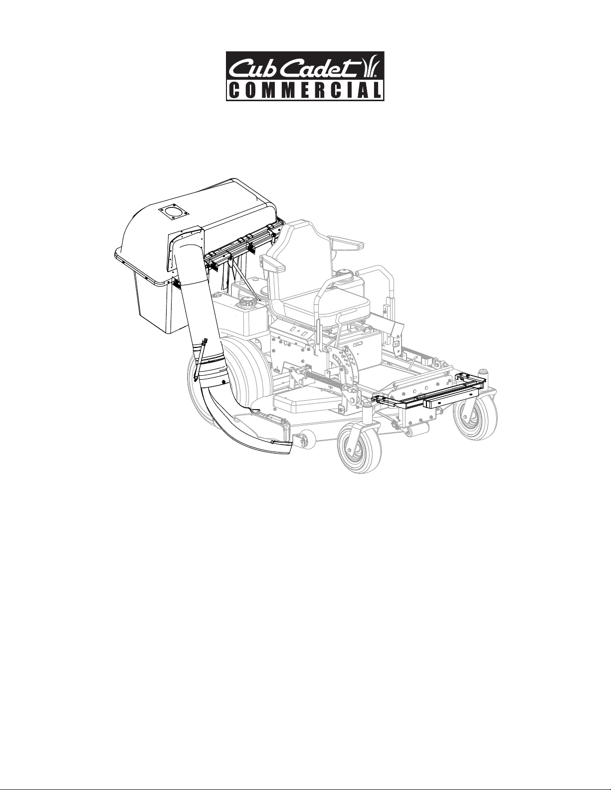
Triple Rear Bagger Kit for Fan Assisted Kit
Model 590-852-150
for use on M48/54/60 “Tank” Model Mowers
(Mower sold separately)
IMPORTANT: Read safety rules and instructions carefully
Cub Cadet LLC., P.O. Box 368023, Cleveland, Ohio 44136
PRINTED IN U.S.A.
FORM NO.
769-01702A.fm
(3/2005)
Page 2
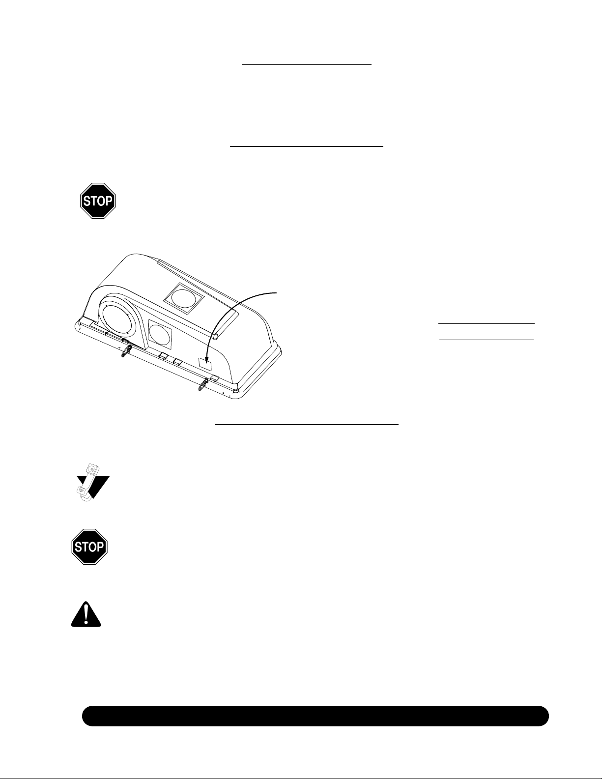
TABLE OF CONTENTS
Content Page
Loose Parts......................................................................................................................7
Assembly & Operation .....................................................................................................8
Parts List..........................................................................................................................12
FINDING MODEL NUMBER
This Operator’s Manual is an important part of your new accessory for your mower. It will help you assemble, and operate
the unit for best performance. Please read and understand what it says.
Before you start assembling your new equipment, please locate the model plate on the equipment and
copy the information from it in the space provided below. The information on the model plate is very
important if you need help from our Customer Support Department or an authorized dealer.
•You can locate the model number in the front, left portion of the plastic grass catcher cover. For
future reference, please copy model number and serial number of the mower accessory in the
space below.
Look for the model plate here
Copy the model number here:
Copy the serial number here:
CALLING CUSTOMER SUPPORT
If you have difficulty assembling this product or have any questions regarding the controls, operation or maintenance of
this unit, please call the customer support department.
Call 1-877-282-8684 to reach the Customer Dealer Referral Line. Please have your unit’s model number and
serial number ready when you call. See previous section to locate this information. You will be asked to enter
the serial number in order to process your call.
This Triple Rear Bagger Kit is designed for use on Cub Cadet M48/54/60 “Tank” mower models with plastic
chute deflectors only.
WARNING: This symbol points out important safety instructions which, if not followed, could endanger the
personal safety and/or property of yourself and others. Read and follow all instructions in this manual before
attempting to operate this bagger.
For more details about your unit, visit our website at www.cubcadet.com
2
Page 3

SECTION 1: IMPORTANT SAFE OPERATION PRACTICES
WARNING: This symbol points out important safety instructions which, if not followed, could endanger
the personal safety and/or property of yourself and others. Read and follow all instructions in this manual
before attempting to operate this machine. Failure to comply with these instructions may result in personal
injury. When you see this symbol—heed its warning.
WARNING: The Battery and Engine Exhaust contains chemicals known to the State of California
to cause cancer, birth defects or other reproductive harm. The battery and posts contain lead;
wash hands after handling
WARNING: This machine was built to be operated according to the rules for safe operation in this
manual. As with any type of power equipment, carelessness or error on the part of the operator can result in
serious injury. This machine is capable of amputating hands and feet and throwing objects. Failure to
observe the following safety instructions could result in serious injury or death.
General Operation
1. Read, understand, and follow all instructions on the
machine and in the manual(s) before attempting to
assemble and operate. Keep this manual in a safe place
for future and regular reference and for ordering
replacement parts.
2. Be familiar with all controls and their proper operation.
Know how to stop tractor and disengage controls quickly.
3. Never allow children under 14 years old to operate this
machine. Children 14 years old and over should read and
understand the operation instructions and safety rules in
this manual and should be trained and supervised by a
parent.
4. Never allow adults to operate this machine without proper
instruction.
5. To help avoid blade contact or a thrown object injury,
keep bystanders, helpers, children and pets at least 75
feet from the machine while it is in operation. Stop
machine if anyone enters the area.
6. Thoroughly inspect the area where the equipment is to be
used. Remove all stones, sticks, wire, bones, toys, and
other foreign objects which could be picked up and
thrown by the blade(s). Thrown objects can cause
serious personal injury.
7. Plan your mowing pattern to avoid discharge of material
toward roads, sidewalks, bystanders and the like. Also,
avoid discharging material against a wall or obstruction
which may cause discharged material to ricochet back
toward the operator.
8. Always wear safety glasses or safety goggles during
operation and while performing an adjustment or repair to
protect your eyes. Thrown objects which ricochet can
cause serious injury to the eyes.
9. Wear sturdy, rough-soled work shoes and close-fitting
slacks and shirts. Loose fitting clothes and jewelry can be
caught in movable parts. Never operate this machine in
bare feet or sandals.
10. Be aware of the mower and attachment discharge
direction and do not point it at anyone. Do not operate the
mower without the discharge cover or entire grass
catcher in its proper place.
11. Do not put hands or feet near rotating parts or under the
cutting deck. Contact with the blade(s) can amputate
hands and feet.
12. A missing or damaged discharge cover can cause blade
.
contact or thrown object injuries.
13. Stop the blade(s) when crossing gravel drives, walks, or
roads and while not cutting grass.
14. Watch for traffic when operating near or crossing
roadways. This machine is not intended for use on any
public roadway.
15. Do not operate the machine while under the influence of
alcohol or drugs.
16. Mow only in daylight or good artificial light.
17. Never carry passengers.
18. Blades disengage when operating in reverse. Back up
slowly. Always look down and behind before and while
backing to avoid a back-over accident.
19. Slow down before turning. Operate the machine
smoothly. Avoid erratic operation and excessive speed.
20. Disengage blade(s), set parking brake, stop engine and
wait until the blade(s) come to a complete stop before
removing grass catcher, emptying grass, unclogging
chute, removing any grass or debris, or making any
adjustments.
21. Never leave a running machine unattended. Always turn
off blade(s), place transmission in neutral, set parking
brake, stop engine and remove key before dismounting.
22. Use extra care when loading or unloading the machine
into a trailer or truck. This unit should not be driven up or
down ramp(s), because the unit could tip over, causing
serious personal injury. The unit must be pushed
manually on ramp(s) to load or unload properly.
23. Muffler and engine become hot and can cause a burn. Do
not touch.
24. Check overhead clearances carefully before driving
under low tree branches, wires, door openings etc.,
where the operator may be struck or pulled from the unit,
which could result in serious injury.
25. Disengage all attachment clutches, depress the brake
pedal completely and shift into neutral before attempting
to start engine.
26. Your machine is designed to cut normal residential grass
of a height no more than 10”. Do not attempt to mow
through unusually tall, dry grass (e.g., pasture) or piles of
dry leaves. Dry grass or leaves may contact the engine
exhaust and/or build up on the mower deck presenting a
potential fire hazard.
27. Use only accessories and attachments approved for this
machine by the machine manufacturer. Read,
3
Page 4

understand and follow all instructions provided with the
accessory or attachment.
28. Data indicates that operators, age 60 years and above,
are involved in a large percentage of tractor-related
injuries. These operators should evaluate their ability to
operate the tractor safely enough to protect themselves
and others from serious injury.
29. If situations occur which are not covered in this manual,
use care and good judgment. Contact your Cub Cadet
dealer for assistance.
Slope Operation
Slopes are a major factor related to loss of control and tip-over
accidents which can result in severe injury or death. All slopes
require extra caution. If you cannot back up the slope or if you
feel uneasy, do not mow it.
For your safety, use the slope gauge included as part of this
manual to measure slopes before operating this unit on a
sloped or hilly area. If the slope is greater than 15 degrees as
shown on the slope gauge, do not operate this unit on that
area.
Do:
1. Mow across slopes, not up and down. Exercise extreme
caution when changing direction on slopes.
2. Watch for holes, ruts, bumps, rocks, or other hidden
objects. Uneven terrain could overturn the machine. Tall
grass can hide obstacles.
3. Use slow speed. Choose a low enough speed setting so
that you will not have to stop mowing while on the slope.
Tires may lose traction on slopes.
4. Follow the manufacturer’s recommendations for wheel
weights or counterweights to improve stability of the
machine. Use extra care with grass catchers or other
attachments. These can change stability of the machine.
5. Keep all movement on the slopes slow and gradual. Do
not make sudden changes in speed or direction. Rapid
engagement or braking could cause the front of the
machine to lift and rapidly flip over backwards which could
cause serious injury.
6. Avoid starting or stopping on a slope. If tires lose traction,
disengage the blade(s) and proceed slowly off of the
slope.
Do Not:
1. Do not turn on slopes unless necessary; then, turn slowly
and gradually uphill, if possible.
2. Do not mow near drop-offs, ditches or embankments. The
mower could suddenly turn over if a wheel is over the
edge of a cliff, ditch, or if an edge caves in.
3. Do not try to stabilize the machine by putting your foot on
the ground.
4. Do not use a grass catcher on steep slopes.
5. Do not mow on wet grass. Reduced traction could cause
sliding.
6. Do not tow heavy pull behind attachments (e.g. loaded
dump cart, lawn roller, etc.) on slopes greater than 5
degrees. When going down hill, the extra weight tends to
push the machine and may cause you to lose control. (e.g.
tractor may speed up, braking and steering ability are
reduced, attachment may jack-knife and cause machine
to overturn).
Children
1. Tragic accidents can occur if the operator is not alert to
the presence of children. Children are often attracted to
the machine and the mowing activity. They do not
understand the dangers. Never assume that children will
remain where you last saw them.
a. Keep children out of the mowing area and in
watchful care of a responsible adult other than the
operator.
b. Be alert and turn machine off if a child enters the
area.
c. Before and while backing, look behind and down
for small children.
d. Never carry children, even with the blade(s) shut
off. They may fall off and be seriously injured or
interfere with safe machine operation.
e. Use extreme care when approaching blind corners,
doorways, shrubs, trees or other objects that may
block your vision of a child who may run into the
machine.
f. Disengage the cutting blade(s) before moving in
reverse.
g. Keep children away from hot or running engines.
They can suffer burns from a hot muffler.
h. Remove key when machine is unattended to
prevent unauthorized operation.
2. Never allow children under 14 years old to operate
the machine. Children 14 years old and over should
read and understand the operation instructions and
safety rules in this manual and should be trained
and supervised by a parent.
Towing
1. Tow only with a machine that has a hitch designed for
towing. Do not attach towed equipment except at the hitch
point.
2. Follow the manufacturers recommendation for weight
limits for towed equipment and towing on slopes.
3. Never allow children or others in or on towed equipment.
4. On slopes, the weight of the towed equipment may cause
loss of traction and loss of control.
5. Travel slowly and allow extra distance to stop.
Service
Safe Handling Of Gasoline
1. To avoid personal injury or property damage use extreme
care in handling gasoline. Gasoline is extremely
flammable and the vapors are explosive. Serious personal
injury can occur when gasoline is spilled on yourself or
your clothes which can ignite. Wash your skin and change
clothes immediately.
a. Use only an approved gasoline container.
b. Never fill containers inside a vehicle or on a truck
or trailer bed with a plastic liner. Always place
containers on the ground away from your vehicle
before filling.
c. When practical, remove gas-powered equipment
from the truck or trailer and refuel it on the ground.
If this is not possible, then refuel such equipment
on a trailer with a portable container, rather than
from a gasoline dispenser nozzle.
d. Keep the nozzle in contact with the rim of the fuel
tank or container opening at all times until fueling is
4
Page 5

complete. Do not use a nozzle lock-open device.
e. Extinguish all cigarettes, cigars, pipes and other
sources of ignition.
f. Never fuel machine indoors.
g. Never remove gas cap or add fuel while the
engine is hot or running. Allow engine to cool at
least two minutes before refueling.
h. Never over fill fuel tank. Fill tank to no more than
½ inch below bottom of filler neck to allow space
for fuel expansion.
i. Replace gasoline cap and tighten securely.
j. If gasoline is spilled, wipe it off the engine and
equipment. Move unit to another area. Wait 5
minutes before starting the engine.
k. To reduce fire hazards, keep machine free of
grass, leaves, or other debris build-up. Clean up
oil or fuel spillage and remove any fuel soaked
debris.
l. Never store the machine or fuel container inside
where there is an open flame, spark or pilot light
as on a water heater, space heater, furnace,
clothes dryer or other gas appliances.
m. Allow a machine to cool at least 5 minutes before
storing.
General Service
1. Never run an engine indoors or in a poorly ventilated
area. Engine exhaust contains carbon monoxide, an
odorless, and deadly gas.
2. Before cleaning, repairing, or inspecting, make certain
the blade(s) and all moving parts have stopped.
Disconnect the spark plug wire and ground against the
engine to prevent unintended starting.
3. Periodically check to make sure the blades come to
complete stop within approximately (5) five seconds after
operating the blade disengagement control. If the blades
do not stop within this time frame, your unit should be
serviced professionally by an authorized dealer.
4. Check park brake operation frequently. Adjust and
service as required.
5. Check the blade(s) and engine mounting bolts at
frequent intervals for proper tightness. Also, visually
inspect blade(s) for damage (e.g., excessive wear, bent,
cracked).
Replace the blade(s) with the original equipment
manufacturer’s (O.E.M.) blade(s) only, listed in this
manual. “Use of parts which do not meet the original
equipment specifications may lead to improper
performance and compromise safety!”
6. Mower blades are sharp. Wrap the blade or wear gloves,
and use extra caution when servicing them.
7. Keep all nuts, bolts, and screws tight to be sure the
equipment is in safe working condition.
8. Never tamper with the safety interlock system or other
safety devices. Check their proper operation regularly.
9. After striking a foreign object, stop the engine, disconnect
the spark plug wire(s) and ground against the engine.
Thoroughly inspect the machine for any damage. Repair
the damage before starting and operating.
10. Never attempt to make adjustments or repairs to the
machine while the engine is running.
11. Grass catcher components and the discharge cover are
subject to wear and damage which could expose moving
parts or allow objects to be thrown. For safety protection,
frequently check components and replace immediately
with original equipment manufacturer’s (O.E.M.) parts
only, listed in this manual. “Use of parts which do not
meet the original equipment specifications may lead to
improper performance and compromise safety!”
12. Do not change the engine governor settings or overspeed the engine. The governor controls the maximum
safe operating speed of the engine.
13. Maintain or replace safety and instruction labels, as
necessary.
14. Observe proper disposal laws and regulations for gas,
oil, etc. to protect the environment.
Your Responsibility
Restrict the use of this accessory and the tractor to persons who read, understand and follow the warnings and
instructions in this manual and on the machine.
IMPORTANT:
Tractor models only. It will NOT mount, nor operate safely or properly, on any other brand of tractor
regardless of the tractor’s compatibility with similar accessories.
This Triple Rear Bagger with Fan Assist Kit is designed for use on Cub Cadet Commercial
5
Page 6

Slope Gauge
Use this page as a guide to determine slopes where you may not operate safely. Do not operate
your equipment on such slopes.
Operate M48/54/60 Tank mowers across the face of slopes, never up and down slopes.
and you could slip, resulting in serious injury.
overturn and cause serious injury. If operating a walk-behind mower on such a slope, it is extremely difficult to maintain your footing
Do not mow on inclines with a slope in excess of 15 degrees (a rise of approximately 2-1/2 feet every 10 feet). A riding mower could
WARNING
15°
F
O
L
D
O
N
D
O
T
T
E
D
L
I
N
E
,
R
E
P
R
E
S
E
N
T
I
N
G
A
1
5
°
S
L
O
P
E
A CORNER OF A BUILDING
OR A FENCE POST
SIGHT AND HOLD THIS LEVEL WITH A VERTICAL TREE
A POWER POLE
6
Page 7

SECTION 2: LOOSE PARTS
The grass catcher kit is shipped with following loose parts in the carton. Please remove all loose parts from the carton before
discarding it. Compare with Figure 1 to check that no parts are missing or misplaced. Also identification of these loose parts at
this point will help in assembly.
Hardware Pack
Bag Cover
Grass Bag (3)
Extension Tube
Lock Pin (2)
Weight Bar Bracket
& Weight Bar
Figure 1
Catcher Tube
Chute Elbow
shown for reference
Catcher Support
Bracket
Upright Gusset (2)
Upright Mounting
Bracket (2)
Boot Mount
Plate
NOTE: For ease of assembly, group the items of the hardware pack according to Figure 2. These categories are referred to in
assembly instructions later in this manual. The hardware items are not drawn to scale here.
Retainer
Hook (2)
Hex Bolt (9)
1/4-20 x
0.620”
Bell
Washer (5)
Flat
Washer (2)
Flange
Lock Nut (9)
NOTE:
These hardware
pieces will only be
included in the hardware
pack if the retainer hook
is shipped unassembled.
See page 10.
Group E
U Bolt (2)
Hex Bolt (2)
3/8-16 x 6.25”
Group A
Top Lock
Flange
Nut (6)
Hex Bolt (2)
1/2-13 x 1.0”
Lock Nut (2)
Group B
Shoulder
Screw (2)
3/8-16
Belleville
Washer (2)
Flange
Lock Nut (2)
Group C
Hex Bolt (2)
3/8-16 x 1.0”
Carriage
Bolt (2)
3/8-16 x 1.0”
Carriage
Bolt
3/8-16 x 1.25”
Top Lock
Flange
Nut (5)
Group D
Figure 2
7
Page 8

SECTION 3: ASSEMBLY & OPERATION
Before Assembly
NOTE: References to left, right, front and rear of the
mower are from the operator’s position. See page 2 for
chute deflector requirement.
• Place the mower on a firm and level surface, disengage
PTO, stop mower engine and set the parking brake.
• Identify all loose parts according to Figure 1 on page 7.
Identify all the items of the hardware pack according to
Figure 2 on page 7.
Tools Req u i r e d
1. Socket and adjustable wrenches or wrenches of the
following sizes: 1/2, 3/4, 9/16 and 15/16 inch.
2. Torque wrench
Attaching Weight Bars
• Remove the two bolts that hold two weight bars on the
rear bumper cross bar of the mower. Remove the two
weight bars. See Figure 3.
• Secure all weight bars to the weight bar bracket and the
mower frame with hex bolt (6.25”) and top lock flange nut
from Group A of the hardware pack. See Figure 5.
Repeat on the other side.
Flange
Nut
Weight
Bar (Old)
Weight
Bar Bracket
Weight
Bar (New)
Weight
Bar (Old)
Hex
Bolt
Figure 5
Assembling the Catcher Support Bracket
Assemble the Upright Gussets to the Upright Mounting
Brackets using the hex bolts and flange nuts from Group D.
Next, attach the assembled Gussets to the Catcher Support
Bracket using the Lock Pins. See Figure 6.
Catcher Support Bracket
Bumper Cross Bar
Weight Bars
Figure 3
• Place weight bar bracket on the front frame of the mower.
See Figure 3 .
• Secure with an U Bolt and two center lock flange nuts
from Group A of the hardware pack on each side of the
front axle of the mower. See Figure 4.
Front Axle
Center Lock
Flange Nut
Weight Bar
Bracket
U Bolt
Figure 4
• Place the three weight bars as shown in Figure 5. Two of
these weight bars were removed from the rear of the
mower while the third was included in the bagger kit.
Lock Pin
Hardware Pack
Group D
Upright Gusset
Upright Mounting
Bracket
Figure 6
Attaching Catcher Support Bracket
With the two upright mounting brackets and the two upright
gussets attached to the two ends of the catcher support
bracket, as in the previous step:
• Remove the two hex bolts on each side of the rear
bumper plate, located in positions A and B in Figure 7.
Save the hardware.
• Place the catcher support bracket assembly on the rear
frame of the mower aligning the hole on each upright
mounting bracket to corresponding hole at A or B. See
Figure 7.
8
Page 9

• Secure the upright mounting brackets to the bumper
plate with the hardware removed earlier. Do not tighten
the nuts at this point.
• Hang the three grass bags using notches on the catcher
support bracket. See Figure 8.
Grass Bag
Cover
Catcher
Mounting
Bracket
B
A
Bumper Plate
Upright Mounting
Bracket
Figure 7
• Align the hole on each gusset (part of the same catcher
support bracket assembly) to the corresponding hole on
the gas tank mount on each side. See locations C & D in
Figure 7.
NOTE: If there is no pre-existing hole on the gas tank mount
(in older models of mower), drill one matching hole on each
gas tank mount frame.
• Secure gusset to each gas tank mount with a hex bolt
and lock nut from Group B of the hardware pack. See
Figure 7.
• Tighten all four nuts on the catcher support bracket
assembly now.
Attaching Grass Bag & Cover
• Align the holes on the hinges of the grass bag cover with
the corresponding holes on the catcher support bracket.
See Figure 8.
• Insert shoulder screw from Group C of the hardware pack
through the hinge on the support bracket and the grass
bag cover. See Figure 8.
NOTE: Make sure the clasp of the lock pins are under the bar
on the catcher support bracket.
• Secure with belleville washer and flange lock nut with the
crown side of washer going against the shoulder screw.
These are also in Group C.
• Repeat with the second set of hardware through the
second hinge of the grass bag and support bracket from
the opposite direction. See Figure 8.
NOTE: After installation, make sure the grass bag cover
pivots on the support tube and opens.
Notches
H
i
n
g
Catcher
Support
Bracket
C
Upright Gusset
e
s
Notches
Upright
Mounting
D
Bracket
Bumper Plate
Gas Tank
Mount
Figure 8
Assembling the Induction Air Kit
See the “Fan Assist Kit” Manual included with the Fan unit.
Attach Boot Mount Plate to Chute Elbow
Locate the Boot Mount Plate, packaged with your loose parts
in this carton. Locate the Chute Elbow packaged with your
Fan Assist unit. Attach the Boot Mount Plate to the Chute
Elbow:
1. Insert 5 Hex Bolts from Group E in your hardware pack,
down through the Boot Mount plate and Chute Elbow.
See Figure 9
2. Secure with a Bell Washer and Flange Lock Nut.
Boot Mount
Hex Bolt
Bell Washer
Flange Lock
Nut
Figure 9
Assembling Discharge Chute
• Lift the chute deflector up and place the chute elbow
along the opening on the cutting deck of the mower.
• Slide the two ends of the boot mount, attached to the
discharge chute elbow, under the chute deflector
mounting bracket. Follow direction of arrows in Figure 10.
9
Page 10

NOTE: Make sure that longer end of the boot mount firmly
secures around the bolt head on the chute mounting bracket.
The other end of boot mount should be securely placed
between the chute mounting bracket and the flange of the
deck opening. See Figure 10 .
Discharge
Chute
NOTE: Grass catcher has been left out of picture for clarity.
Boot Mount
Chute Deflector
Figure 10
• Insert the curved end of the chute tube into the opening in
the grass bag cover. See Figure 11. Slide the chute tube
further into the cover opening for ease of assembly in the
next step.
• Insert a hex bolt from Group E of the hardware pack
through the retainer hook and the chute tube at this hole.
Secure with flange lock nut from the same hardware pack
group. See Figure 12 inset.
• Repeat with the other set of hardware from Group E at
the other hole on the chute tube.
NOTE: These hardware pieces will only be included in the
hardware pack if the retainer hook is shipped unassembled.
Chute
Chute Tube
Retainer
Hook
Hex Bolt
Flange Lock
Nut
Extension Tube
Retainer Strap
Tube
Chute
Elbow
Figure 12
Insert end
of chute tube
here
NOTE: Mower is not shown
for clarity.
Figure 11
NOTE:
and for identification purposes, locate these notches before
starting to assemble.
• Insert the end of the chute extension, that does not have
• Slide the chute assembly down and insert the other end
• Pull each retainer strap to the corresponding retainer
The chute extension has raised notches on one end,
raised notches, into the chute tube.
of the chute extension into the chute elbow aligning the
raised notches on both parts.
hook on the chute tube and attach.
NOTE: If the retainer hooks were not attached to the chute
tube before shipping, please attach it as follows.
• Place the retainer hook in one of the two holes on the
chute tube. See Figure 12 inset.
Replacing Muffler Tailpipe
Some older model mowers may have a rear facing tailpipe. If
your mower is equipped with this tailpipe, you will need to
order a straight tailpipe 751-10027 to replace it. Do not
attempt to use the grass catcher kit with the rear-facing
tailpipe.
Rear-Facing
Tailpi pe
Figure 13
10
Page 11

Operating the Grass Catcher
• Lift up the grass bag cover and hold it.
• Lift each grass bag from the notches which hold it, and
move it away from the mower. Do not remove the chute
tube assembly from the unit.
• Holding the bag firmly, empty the contents. Repeat with
the remaining two.
NOTE: Mower cutter deck must be equipped with the
designated hi-lift blades for all three (3) spindle locations for
proper performance.
NOTE: Make sure to dispose of the grass clippings at
appropriate disposal sight only.
11
Page 12

SECTION 4: PARTS LIST FOR MODEL 590-852-150
13
19
22
18
23
31
32
3
30
33
14
21
34
1
10
17
16
10
8
20
14
Chute Elbow shown
for reference, see “Fan
Assist Manual” for details
From the
Mower
13
13
25
27
From the
Mower
24
12
26
12
2
6
7
9
4
5
29
15
13
Page 13

PARTS LIST FOR MODEL 590-852-150
Ref. No. Part No. Description Qty.
1. 16606 Retainer Hook 2
2. 603-04098 Catcher Support Bracket 1
3. 664-04018 Catcher Cover 1
4. 703-05237 Upright Mounting Bracket LH 1
5. 703-05239 Upright Mounting Bracket RH 1
6. 703-05240 Upright Gusset LH 1
7. 703-05241 Upright Gusset RH 1
8. 703-05245A Boot Mount 1
9. 710-0514 Hex Bolt 3/8-16 x 1.0” 2
10. 710-0751 Hex Bolt 1/4-20 x 0.620” 9
11. 710-3034 Carriage Bolt 3/8-16 x 1.25Ӡ 1
12. 711-04160 Lock Pin 2
13. 712-0431 Top Lock Flange Nut 3/8-16 13
14. 712-3027 Flange Lock Nut 1/4-20 9
15. 712-3083 Lock Nut 1/2-13 2
16. 723-0476 Chute Strap 2
17. 731-04423 Extension Tube 1
18. 731-0926B Chute Tube 1
19. 736-0253 Belleville Washer 2
20. 736-0270 Bell Washer 5
21. 736-3092 Flat Washer 2
22. 738-0380 Shoulder Screw 3/8-16 2
23. 764-0251 Triple Grasscatcher bag 3
24. 603-04307 Weight Bar Bracket 1
25. 710-04170 U Bolt 3/8-16 x 1.5” 2
26. 710-3086 Hex Bolt 3/8-16 x 6.25” 2
27. 719-04069 Weight Bar 1
28. 710-3097 Carriage Bolt 3/8-16† 2
29. 710-3131 Hex Screw 1/2-13 2
30. 17201A Bag Frame Hangar Bracket 3
31. 710-0473 Machine Screw #10-24 x .50 12
32. 710-0604A Screw 5/16-18 x .625 12
33. 712-0272 Hex Nut 10-24 12
34. 749-0745A Grass Bag Frame 3
† No Shown
13
Page 14

NOTES:
14
Page 15

NOTES:
15
Page 16

 Loading...