

MTD 490-980-0037 Owner’s Manual
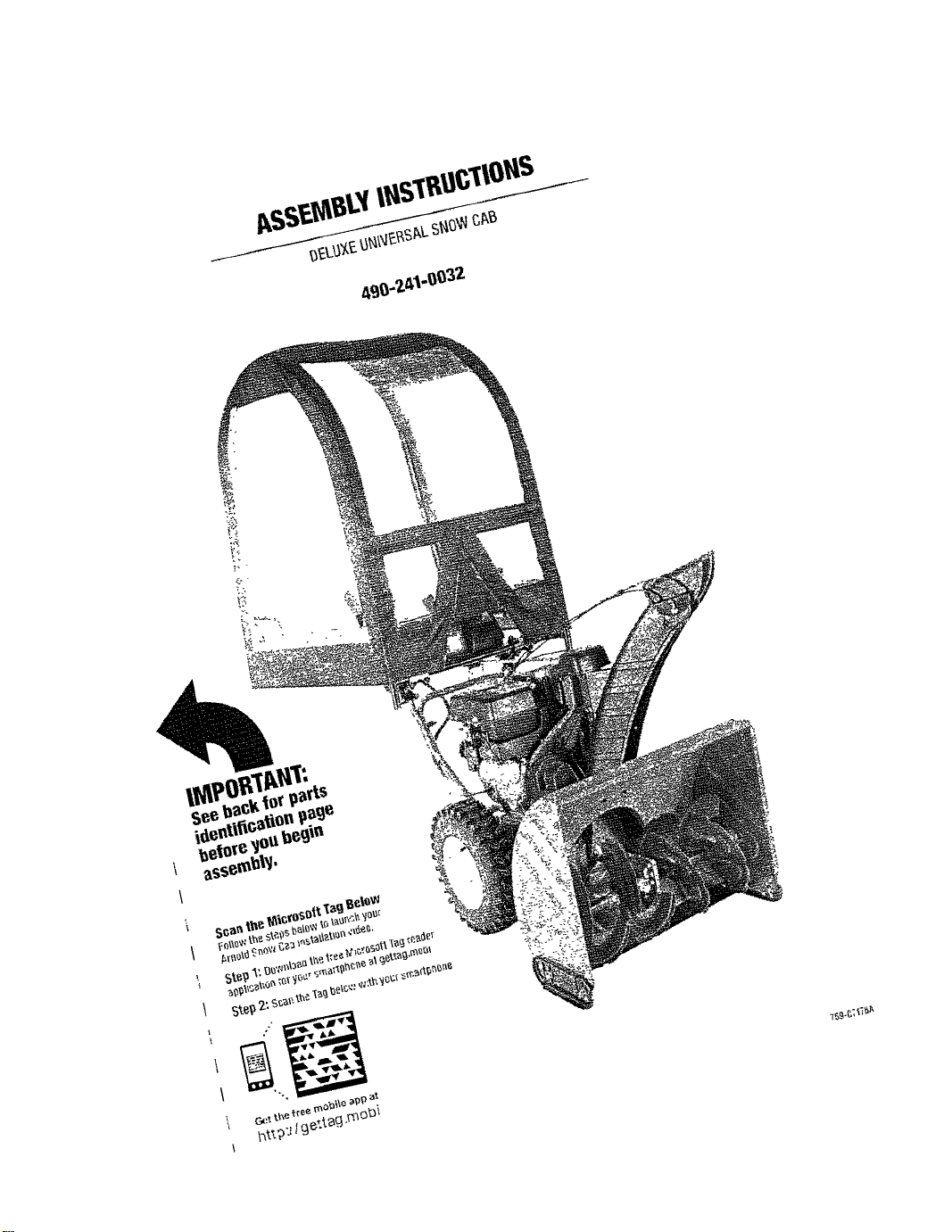
ASSEMBLYINSTRUCTIONS
DELUXEUNIVERSALSNOW CAB
490-241-0032
IMPORTANT:
See backfor parts
identification page
beforeyoubegin
assembly.
"°. ! o . I
G_.,tthe free mobile _pp at
httpJige:tag.mobi
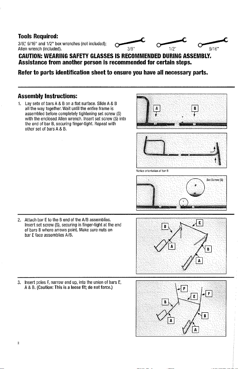
ToolsRequired:
3/B';9/16" and 112"boxwrenches(netincluded);
Allen wrench (included). 3/8" I/2" 9/_6"
CAUTION:WEARINGSAFETYGLASSESISRECOMMENDEDDURINGASSEMBLY,
Assistance from another person is recommended for certain steps,
Refer to parts identification sheet to ensure you have all necessaryparts,
Assembly Instructions:
t. Lay sets of barsA &B on afiat surface. SlideA & B
all theway together.Waituntil the entire frameis
assembledbeforecompletelytighteningset screw (S)
with the enclosedAllenwrench.Insertset screw (S)into
the end of bar B,securingfinger-tight. Repeatwith
other set ofbarsA & B.
Attachbar Eto the Bend of the A/B assemblies.
Insert set screw(S),securingin fingePtight at theend
ofbars Bwhere arrows point.Makesure nuts on
barE faceassembliesAiB.
Insert poles F,narrowend up, into the unionof barsE,
A& B.(Caution;Thisisa looselit; donot force.)
ii!! ii ! ill!iliii !!!i!i!ilil
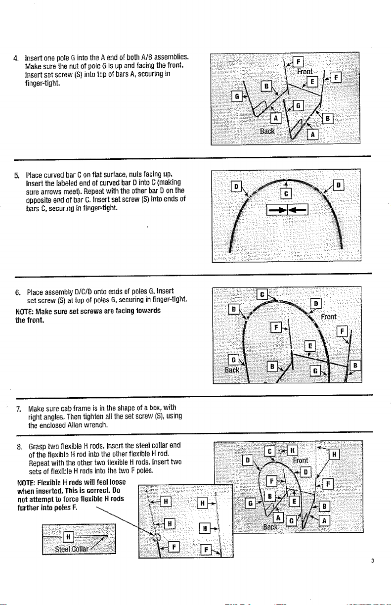
Insert onepole Gintothe A endofbothAIB assemblies.
Make surethe nut of pole(3is up andfacingthe front.
insert set screw (S)into topof barsA, securingin
finger-tight.
Placecurved bar Con fiat surface,nutsfacing up.
Insert the labeledend ofcurvedbar DintoG(making
surearrows meet).Repeatwith the otherbarDon the
oppositeend of bar C.Insertset screw (S)intoendsof
barsC,securinginfinger-tight.
6, Ptaceassembly'DiC/Dontoendsof polesG.Insert
set screw (S)attopof po_esG,securinginfinger-tight.
NOTE:Make sure set screws arefacing towards
the front,
!iiiiiii
7, Makesurecabframe isin theshapeofa box,with
rightangles, Thentighten alltheset screw (S),using
the enclosedAllen wrench,
8. Grasptwoflexible Hrods, Insertthesteelcollarend
of the flexible1trodinto the otherflexibleH rod.
Repeatwith theothertwo flexibleHrods, insert two
sets offlexible H rods intothe two F poles.
NOTE:FlexibleH rods will feelloose
wheninserted,Thisis correct,De
net attempt to force flexibleHrods
further intopolesF.
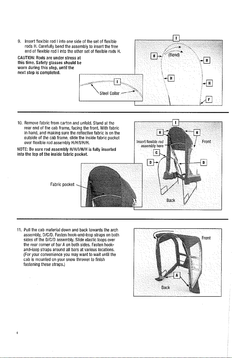
9, Insert flexible rod Iinto onesideofthe setof flexible
rodsH.Carefully bendthe assembly to insertthefree
endof flexible rod I intothe otherset of flexiblerods H.
CAUTION:Rodsareunder stress at
thistime, Safety glassesshouldbe
wornduringthisstep, untilthe
next step is completed,
10. Removefabric from carton andunfold,Standat the
rear end of thecab frame,facing the front. Withfabric
in hand, andmaking surethe reflective fabric is onthe
outsideof the cab frame,slide the insidefabric pocket
overflexible rod assemblyH/Hi!/H/H.
NOTE:Be surerod assembly H!H/I/HIll is fully inserted
into thetop of the inside fabric pocket.
Fabric pocket
11.Pull the cab materialdownand back towardsthe arch
assembly,D/C/D.Fastenhook-and-loopstrapson both
sides of the D/C/Dassembly.Slideelastic loopsover
the rear cornerof barAon both sides. Fastenhook-
and-loopstrapsaroundoil bars at variouslocations.
(Foryour convenienceyou maywantto wait until the
cab is mountedon your snow 1hrowertofinish
fastening thesestraps.)
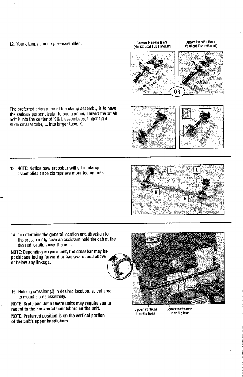
12.Yourc]arr_scanbe pro-assembled.
Thepreferredorientationofthe clampassemblyisto have
the saddtesperpendicularto oneanother,Threadthe small
bolt Pinto thecenterofK & Lassemblies,finger-tight,
Slidesmallertube,L, intolarger tube, K.
13, NOTE:Noticehowcrossbarwill sit [n clamp
assembliesoncecramps are mountedonunit.
Lower Han_[leBars
(HorizontalTubeMount)
UpperHandleBars
(Ve_ioaiTubeMount}
14.Todeterminethegenerallocationanddirectionfor
the crossbar(J),havean assistant hold thecabat the
desiredlocationoverthe unit.
NOTE:Dependingonyourunit,thecrossbarmay be
positionedfacingforward or backward,and above
orbelowanylinkage.
15, Holdingcrossbar(J)indesiredlocation,_electarea
to mountclampassembly.
NOTE:Bruteand JohnDeereunitsmay require youto
mount to the horizontalhandlebarsontheunit.
NOTE:Preferredpositionison theverticalportion
of theunit'supperhandlebars.
Uppervertical
handtebars
LowerhQdzontal
handlebar
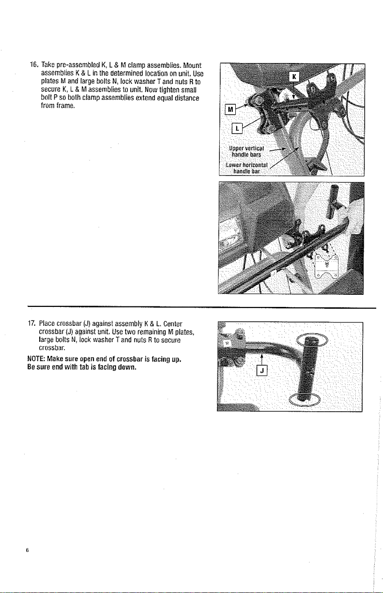
16.Takepre-assembledK, L& M clampassemblies.Mount
assembliesK& Lin the determinedlocationonunit. Use
platesM and largebolts N,lockwasher Tand nuts Rto
secureK,L & Massembliesto unit. Nowtighten small
bolt Pso bothctampassembliesextendequaldistance
from frame.
17. Placecrossbar(J)againstassembly K& L Center
crossbar(J) againstunit, Usetwo remainingM plates,
largebolts N, rockwasherTand nutsRto secure
crossbar.
NOTE:Make sure openend ofcrossbar is facing up,
Besureend with tabis facingdown,
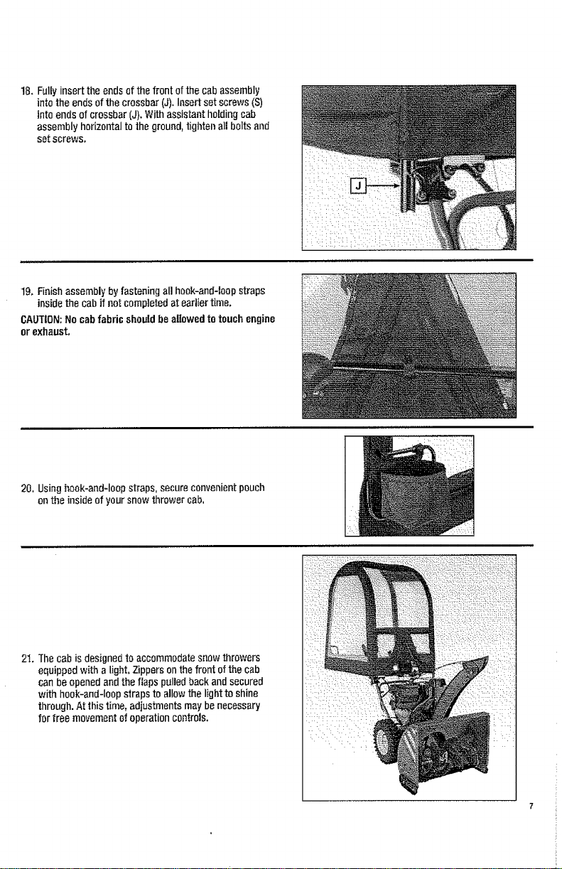
18. Fully insert the endsof thefront ofthe cabassembly
into theendsof thecrossbar(J).Insert set screws (S)
into endsof crossbar(J).With assistantholdingcab
assemblyhorizontalto the ground, tightenall boltsand
setscrews.
19. Finishassemblybyfasteningall hook-and-loopstraps
insidethe cab ifnotcompletedatearliertime.
CAUTION:No cabfabric shouldbeallowedtotouchengine
orexhaust,
20, Usinghook-and-loopstraps, secure convenientpouch
onthe insideof your snowthrower cab,
2_.Thecab is designedto accommodatesnowthrowers
equippedwith a light,Zippersonthefront of the cab
can beopenedand theflaps pulledbackandsecured
with hook-and-loopstrapsto allowthe lightto shine
through.At this time, adjustmentsmay benecessary
for free movementof operationcontrols.
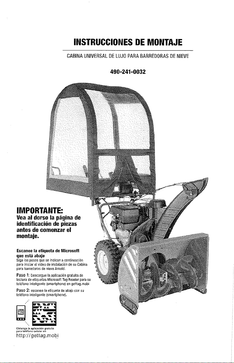
INSTRUCCIONESDE MONTAJE
CABINAUNIVERSALDELUJOPARABARREDORASDENIEVE
IMPORTANTE:
Vea a! dorso la p_gina de
identificaci6n de piezas
antes de comenzar el
montaje.
490-241-0032
 Loading...