

Page 1

OPERA TOR'S MANUAL
46"
SNOW
BLADE
Model Number
190-822
IMPORTANT: READ SAFETY RULES AND INSTRUCTIONS CAREFULLY
MTD PRODUCTS INC. P.O. BOX 368022 CLEVELAND, OHIO 44136-9722
PRINTED IN U.S.A. FORM NO. 47448
Page 2
RULES FOR SAFE OPERATION
Any power equipment can cause injury if operated improperly or if the user does not understand how to operate
the equipment. Exercise caution at all times when operating equipment.
1. Read the tractor and snow blade owners manuals and know how to operate your tractor before using tractor with snow
blade attachment.
2. Never operate tractor and snow blade without wearing proper clothing suited to weather conditions and operation of
controls.
3. Never allow children to operate tractor and snow blade, and do not allow adults to operate without proper instructions.
4. Always begin with transmission in first (low) gear and gradually increase speed as required.
LOOK FOR THIS SYMBOL TO POINT OUT
IMPORTANT SAFETY PRECAUTIONS. IT
MEANS -- ATTENTION! BECOME ALERT! YOUR
SAFETY IS INVOLVED.
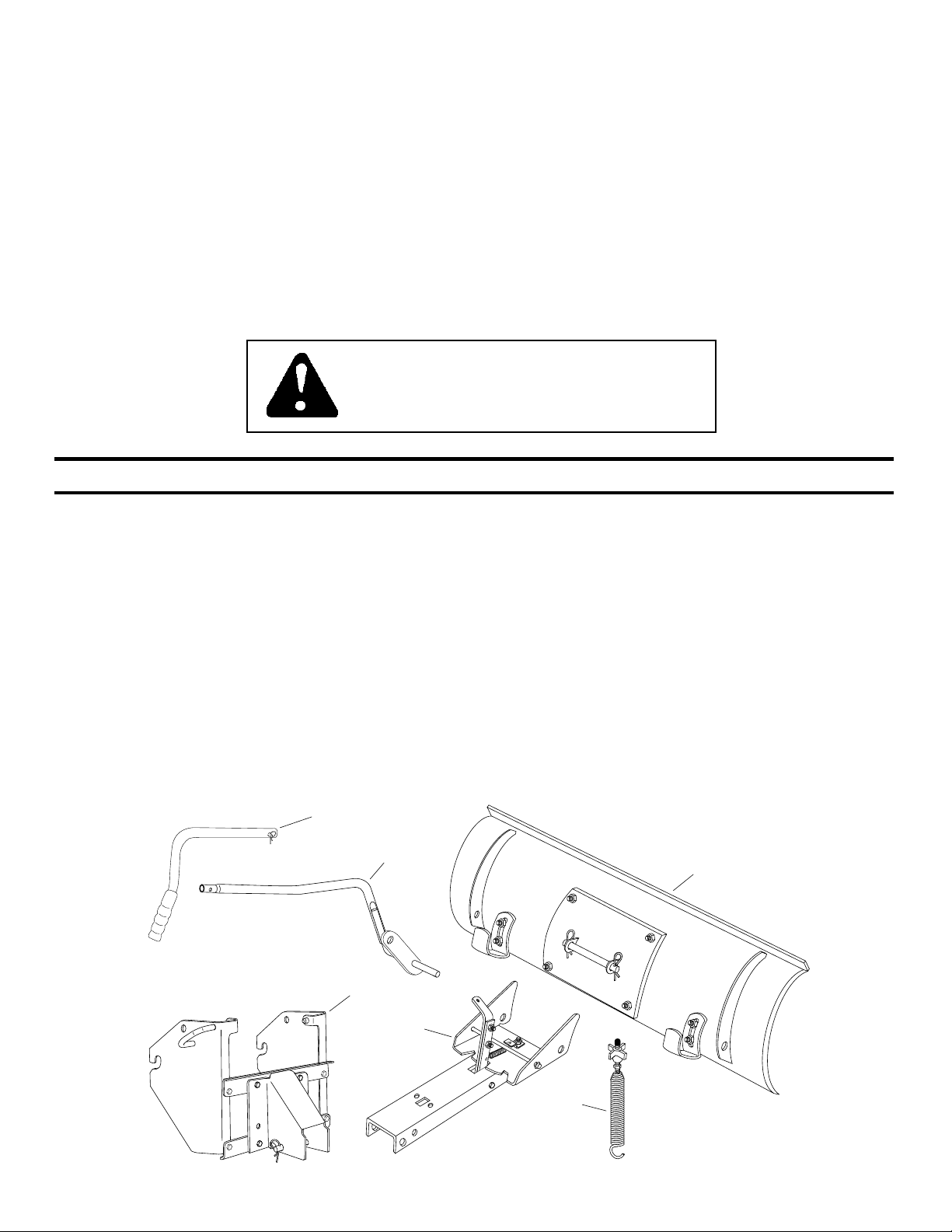
UNPACKING
Open carton. Remove parts and literature. Make
certain all parts and literature are removed before the
carton is discarded.
Lay out all parts according to the illustration below.
CARTON CONTENTS (Loose Parts in Carton)
A 1 Upper Lift Handle w/Clevis Pin & Hairpin Clip
B 1 Lower Lift Handle Assembly
C 1 Hitch Assembly w/ Channel Pivot Pin & Hairpin Clips(2)
D 1 Channel Assembly
E 1 Blade Adjusting Spring w/Bolt, Nut, Washer & Knob
F 1 Blade Assembly w/Pivot Shaft & Hairpin Clips(2)
A
B
TOOLS REQUIRED FOR ASSEMBLY
No Tools Required
F
C
D
E
2
Page 3
PREP ARING THE LAWN TRACTOR
A
B
C
D
NOTE: When preparing the lawn tractor for assembly of
snow blade attachment, store all items removed with the
mowing deck.
1. Allow engine, muffler and exhaust deflector to cool
before beginning.
2. Disconnect the spark plug wire(s) from the spark plug(s)
and ground against the engine.
3. Remove the mowing deck as instructed in the belt
removal section of the owner's manual for the lawn
tractor.
WARNING: Before beginning preparation,
F
select a firm and level surface which is large
enough to accommodate the snow blade
E
attachment and tractor. Engage brake lock.
4. Remove the pivot shaft with hairpin clips from the
welded brackets on the back of the blade. To attach
the channel assembly to the blade, align the holes in
the pivot plate with the holes in the welded brackets.
Insert the pivot shaft through the holes, securing it
with the hairpin clips.
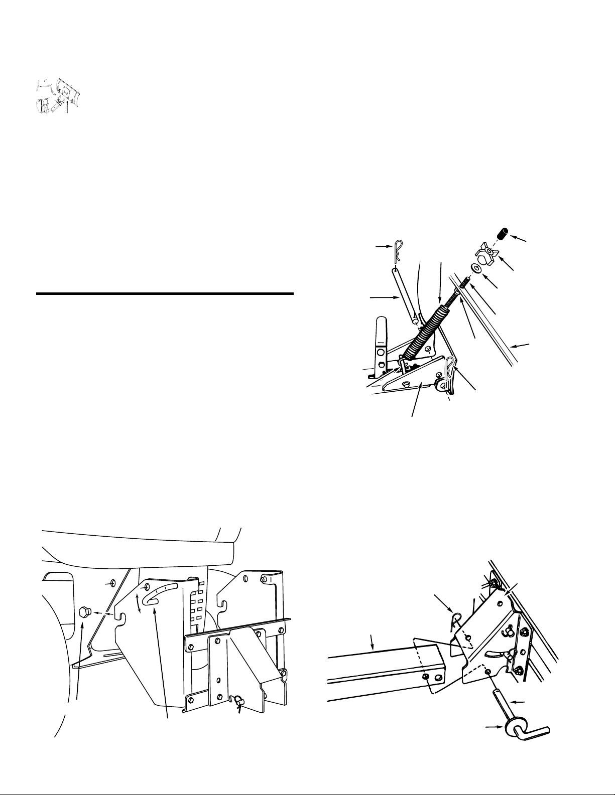
5. Remove the plastic cap, the knob and the washer
from the blade adjusting spring bolt. Adjust the hex
nut on the bolt so that it is screwed approximately 1"
onto the bolt threads. Hook the spring over the spring
mount rod as shown. Place the bolt through the hole
in the top of the blade and reassemble the washer and
the knob onto the bolt. Screw the knob down until tight
against the blade and the hex nut. Place the plastic
cap over the end of the bolt. See figure 2.
HAIR
PIN
CLIP
BLADE
ADJUST
SPRING
PLASTIC
CAP
KNOB
SECTION 1: ASSEMBLY
INSTRUCTIONS
NOTE: Right hand (R.H.) and left hand (L.H.) are deter-
mined from the operators position while seated
on the tractor.
1. To attach the hitch assembly to the front of the tractor,
pull out on the attachment pins and swing the pins
down clear of the holes they were in. See figure 1.
2. Hook the notches in the sides of the hitch assembly
onto the shoulder bolts in the sides of the tractor
frame. See figure 1.
3. To lock the hitch assembly in place, insert the attachment pins back into the holes in the hitch assembly
and into the holes in the sides of the tractor frame.
See figure 1.
PIVOT
WASHER
SHAFT
BOLT
HEX
BLADE
NUT
SPRING
MOUNT
HAIRPIN CLIP
ROD
PIVOT PLATE
Figure 2
6. Remove the channel pivot pin, washer and hairpin
clip from the pivot support bracket. Attach the channel assembly to the tractor by placing the end of the
channel inside the pivot support bracket. Insert the
channel pivot pin through the holes in the pivot support bracket and the channel. Secure with the hairpin
clip. See figure 3.
PIVOT
SUPPORT
HAIRPIN
BRACKET
CLIP
SHOULDER BOLT
ATTACHMENT PIN
Figure 1
CHANNEL
ASSEMBLY
CHANNEL
PIVOT
PIN
WASHER
Figure 3
3
Page 4

7. Remove the hairpin clip from the lift link pin which is
assembled to the pivot support bracket. Insert the end
of the lower lift handle assembly through the notch in
the pivot support bracket and through the holes in the
channel. Align the lift link pin with the hole in the
welded bracket on the lower lift handle assembly.
Insert the lift link pin through the hole in the bracket
and secure it with the hairpin clip. See figure 4.
SECTION 2: OPERATING THE BLADE
A
B
C
D
CAUTION: Inspect the area to be worked
F
carefully before operating the snow blade.
Avoid pipes, roots, curbs or other heavy
E
obstructions.
HAIRPIN
CLIP
LIFT
LINK
PIN
WELDED
BRACKET
CHANNEL
LOWER LIFT
HANDLE ASSEMBLY
Figure 4
8. Remove the clevis pin and hairpin clip from the upper
lift handle. Place the upper lift handle over the lower
lift handle assembly. Align the holes and secure with
the clevis pin and hairpin clip.
UPPER LIFT HANDLE
CLEVIS PIN
HAIRPIN CLIP
LOWER LIFT HANDLE
ASSEMBLY
Figure 5
The lift handle, located on the left side of the snow blade,
is used to raise and lower the blade. Pulling the lift handle
all the way back raises the snow blade. Move the lift
handle forward to lower the snow blade to the ground.
The angle of the blade can be adjusted to the right or left
by pulling back on the angle lock bar, shown in figure 6,
and repositioning the head of the blade to the right, left or
center.
ANGLE
LOCK
BAR
Figure 6
A
B
C
D
CAUTION: Know the terrain. Avoid
F
exceptionally sharp slopes or drop offs which
may be hidden by the snow. Never run the
E
snow blade into heavy material at high speed.
Always begin with the engine speed at the lowest possible setting, and gradually increase speed as required.
When working in a large area, do not attempt to move the
snow or dirt all in the same direction, causing an excessive build-up, which would become larger with each
pass.
A
B
F
C
D
CAUTION: Always lower blade to ground
before leaving tractor.
E
SECTION 3: ADJUSTMENTS
The skid shoes may be adjusted by loosening the two
nuts and repositioning at the desired height.
The tension on the blade head spring can be adjusted to
suit conditions. To stiffen the blade trip action, loosen the
hex nut on the spring bolt and tighten the knob. The
normal adjustment of the spring tension is for the spring
bolt to extend 1" through the hex nut.
4
Page 5

NOTES
5
Page 6

B
B
A
A
3
8
10
30
35
35
46
31
34
32
51
15
14
19
27
20
44
37
43
24
25
11
21
17
13
12
26
4
5
4
4
7
6
6
6
50
36
25
C
C
52
2
1
9
22
29
45
47
47
48
49
33
40
23
25
9
38
28
24
39
41
42
16
16
18
REPAIR PARTS LIST FOR MODEL OEM-190-822 46" SNOW BLADE
6
Page 7

1 Washer
28 24518 1 Hitch Bracket, R.H.
29 24519 1 Hitch Bracket, L.H.
NO. NO.
REF. PART QTY. DESCRIPTION
30 24023 1 Pivot Support Bracket
31 23129 1 Angle Lock Bar (Long)
32 46553 1 Lift Handle, Upper
33 23151 1 Angle Lock Bar (Short)
34 23856 1 Spring Mount Rod
35 44917 2 Palnut, 3/8"
36 43010 1 Cotter Pin 1/8" x 1"
37 43348 1 Angle Lock Spring
38 47501 1 Knob
39 47553 2 Pin, Attachment
40 43362 1 Handle, Grip
41 732-3127 2 Spring, Compression
42 43659 2 Pin, Spring 3/16" x 1"
43 43013 1 Hex Lock Nut, 1/4-20 Thread
R19171616
44 710-0305 2 Carriage Bolt, 3/8-16 x 1-1/4"
45 46065 1 Channel Pivot Pin
46 63034 1 Lift Link Assembly
47 43001 8 Hex Bolt, 3/8-16 x 1"
48 43082 2 Hex Lock Nut, 3/8-16 Thread
49 43003 2 Lock Washer 3/8"
50
47448 1 Owners Manual
51 46071 1 Hex Bolt, 1/4-20 x 3-1/4" Lg. Gr 5
52 43349 1 1/4" x 1" Spring Pin
REPAIR PARTS LIST FOR MODEL OEM-190-822 46" SNOW BLADE
REF. PART QTY. DESCRIPTION
NO. NO.
1 63821 1 Blade - 46"
2 24524 1 Wear Plate - 46"
3 62980 1 Reinforcement Plate Assembly
4 43080 8 Bolt, Carriage 5/16-18 x 3/4"
5 43079 2 Bolt, Carriage 5/16-18 x 1"
6 43064 10 Hex Lock Nut, 5/16-18 Thread
7 43081 4 Washer, 5/16"
8 23070 2 Skid Shoe
9 24520 2 Bracket, Angle Support
10 24347 1 Push Channel
11 43262 1 Hex Lock Nut, 1/2-13 Thread
12 23131 1 Bolt, Special Pivot
13 1540-118 1 Washer, Flat 1/2"
14 23958 1 Plate, Pivot 7 Ga.
15 23130 1 Bracket, Spring Mt.
16 47572 8 Flanged Lock Nut, 3/8-16 Thread
17 23122 1 Shaft, Pivot
18 43070 1 Washer, 3/8" STD.
19 9466R 1 Spring, Blade Adjust
20 44071 1 Hex Bolt, 3/8-16 x 3-1/2"
21 43015 1 Hex Nut, 3/8-16 Thread
7
22 44074 1 Plastic Cap
23 41-42 1 Pin, Clevis 1/4" x 1-1/2"
24 43343 2 Pin, Hair Cotter #4 (1/8")
25 43055 3 Pin, Hair Cotter #3 (3/32")
26 46053 2 Spacer, .28 ID x 1"
27 63283 1 Lift Handle Assembly, Lower
Page 8

If you are having difficulty assembling this product or if you have any
question regarding the controls, operation or maintenance of this unit,
please call the Customer Suport Department. You can reach them by
calling:
1-800-800-7310
 Loading...