

MTD 41FDZ46C799, 41EDZ47C799 Owner’s Manual

Operator’s Manual
4-Cycle
Electric Start Capable
WEEDWACKER®GAS TRIMMERS
Model Nos. 316.74093* & 316.74097*
*The last digit of the model number varies.
• SAFETY
• ASSEMBLY
CAUTION: Before using this product,
read this manual and follow all its Safety
Rules and Operating Instructions.
Sears Brands Management Corporation, Hoffman Estates, IL 60179 U.S.A.
Visit our website: www.craftsman.com
769-11999 / 00 10/16
• OPERATION
• MAINTENANCE
• ESPAÑOL, P. 25

TABLE OF CONTENTS
Safety . . . . . . . . . . . . . . . . . . . . . . . . . . . . . . . . . . . . . . . . . . . . . . .2
Know Your Unit . . . . . . . . . . . . . . . . . . . . . . . . . . . . . . . . . . . . . . . .6
Specifications . . . . . . . . . . . . . . . . . . . . . . . . . . . . . . . . . . . . . . . . .7
Assembly . . . . . . . . . . . . . . . . . . . . . . . . . . . . . . . . . . . . . . . . . . . . .8
Oil and Fuel . . . . . . . . . . . . . . . . . . . . . . . . . . . . . . . . . . . . . . . . . .13
Starting and Stopping . . . . . . . . . . . . . . . . . . . . . . . . . . . . . . . . . .14
Operation . . . . . . . . . . . . . . . . . . . . . . . . . . . . . . . . . . . . . . . . . . .16
Maintenance . . . . . . . . . . . . . . . . . . . . . . . . . . . . . . . . . . . . . . . . .18
Cleaning and Storage . . . . . . . . . . . . . . . . . . . . . . . . . . . . . . . . . .23
Troubleshooting . . . . . . . . . . . . . . . . . . . . . . . . . . . . . . . . . . . . . .24
Warranty . . . . . . . . . . . . . . . . . . . . . . . . . . . . . . . . . . . . . . . . . . . . . .*
Repair Protectio
Service Numbers . . . . . . . . . . . . . . . . . . . . . . . . . . . . . . . . . . . . . . .*
* For Warranty, Repair Protection Agreements, and Service
Number information, please refer to the separate Warranty /
Service Supplement.
n Agre
ements . . . . . . . . . . . . . . . . . . . . . . . . . . . . .*
NOTE: This operator's manual covers multiple models. Features
may vary by model. Not all features in this manual are applicable
to all models. The model depicted may differ from yours.
All information, illustrations and specifications in this manual are based
on the latest product information available at the time of printing. We
reserve the right to make changes at any time without notice.
© Sears Brands, LLC
The purpose of safety symbols is to attract your attention to
possible dangers. The safety symbols, and their explanations,
deserve your careful attention and understanding. The safety
warnings do not by themselves eliminate any danger. The
instructions or warnings they give are not substitutes for proper
accident prevention measures.
SYMBOL MEANING
DANGER:
Failure to obey a safety DANGER symbol WILL result in
serious injury or death to yourself or to others.
WARNING:
Failure to obey a safety WARNING symbol CAN result in
serious injury to yourself or to others.
CAUTION:
Failure to obey a safety CAUTION symbol MAY result in
property damage or injury to yourself or to others.
NOTE: Advises you of information or instructions vital to the
operation
or maintenance of the equipment.
Signals an EXTREME hazard.
Signals a SERIOUS hazard.
Signals a MODERATE hazard.
SAFETY
SPARK ARRESTOR NOTE
NOTE: For users on U.S. Forest Land and in the states of
California, Maine, Oregon and Washington. All U.S. Forest Land
and the state of California (Public Resources Codes 4442 and
4443), Oregon and Washington require, by law that certain internal
combustion engines operated on forest brush and/or grass-covered
areas be equipped with a spark arrestor, maintained in effective
work
maintained for the prevention of fire. Check with your state or local
authorities for regulations pertaining to these requirements. Failure
to follow these requirements could subject you to liability or a fine.
This unit is factory equipped with a spark arrestor. If it requires
replacement, contact a Sears Parts & Repair Service Center to
install the
Read the operator’s manual and follow all warnings and safety
instructions. Failure to do so can result in serious injury to the
operator and/or bystanders.
er, or the engine be constructed, equipped and
ing ord
priate muffler assembly.
appro
CALIFORNIA PROPOSITION 65
WARNING:
known to the state of California to cause cancer, birth defects
or other reproductive harm.
This product contains a chemical
2

• IMPORTANT SAFETY INSTRUCTIONS •
READ ALL INSTRUCTIONS BEFORE OPERATING
WARNING:
instructions must be followed. Please read these
instructions before operating the unit in order to ensure the
safety of the operator and any bystanders. Please keep
these instructions for later use.
• Read the instructions carefully. Be familiar with the controls and
proper use of the unit. Know how to stop the unit and disengage
the controls quickly.
• Stay alert. Do not operate this unit when tired, ill or under the
influence of alcohol, drugs or medication.
• Never allow children to operate the unit. Teens must be trained,
accompanied and supervised by an adult. Never allow adults to
operate the unit witho
• All guards and safety attachments must be installed properly
before operating the unit.
• Inspect the unit before use. Check for damaged parts. Check for
fuel leaks. Make sure all parts operate properly. Make sure all
fasteners are in place and secure. Make sure all moving parts are
properly aligned and are not bound. Replace parts that are cracked,
chipped, or damaged in any way.
orking parts repaired or replaced by an authorized service
w
center. Do not operate the unit with loose or damaged parts.
• Only use the trimming line described in the Specifications section
of this manual. Never use metal-reinforced line, wire, chain or
rope. These can break off and become dangerous projectiles.
• Do not replace the cutting head with rigid or metal blades.
o could result in serious injury.
s
• Be aware of risk of injury to the head, hands and feet.
• Carefully inspect the area before starting the unit. Remove
rocks, broken glass, nails, wire, string and other objects that
may be thrown or become entangled with the unit.
• Clear the area of children, bystanders and pets; keep them
outside a 50-foot (15 m) radius, at a minimum. Even then, they are
still at
risk fro
eye protection. If you are approached, stop the unit immediately.
• Squeeze the throttle control and check that it returns
automatically to the idle position. Make all adjustments or
repairs before using the unit.
• Do not change the engine governor settings or overspeed the
engine.
• This unit is intended for occasional, household use only.
m thrown objects. Encourage bystanders to wear
ut pro
When using the unit, all safety
per instruction.
Have all damaged or improperly
Doing
SAFETY WARNINGS FOR GAS UNITS
WARNING:
its vapors can explode if ignited. Take the following
precautions:
• Store fuel only in containers specifically designed and approved
for the storage of such materials.
• Always stop the engine and allow it to cool before filling the
tank. Never remove the fuel tank cap or add fuel when the
engine is hot. Always loosen the fuel tank cap slowly to relieve
any pressure in the tank before fueling.
• Always add fu
there are no sparks or flames. DO NOT smoke.
• Never operate the unit without the fuel cap securely in place.
• Avoid creating a source of ignition for spilled fuel. Wipe up any
spilled fuel from the unit immediately, before starting the unit.
Move the unit at least 30 ft. (9.1 m) from the fueling source and
site before starting the engine. DO NOT smoke.
• N
ever start or run the unit inside a closed ro
Breathing exhaust fumes can kill. Operate this unit only in a wellventilated outdoor area.
el in a clean, well-ventilated outdoor are
Gasoline is highly flammable and
a where
om or building.
WHILE OPERATING
• Wear safety glasses or goggles that meet current ANSI / ISEA
Z87.1 standards and are marked as such. Wear ear/hearing
protection when operating this unit. Wear a face mask or dust
mask if the operation is dusty.
• Wear heavy long pants, boots, gloves and a long sleeve shirt. Do
not wear loose clothing, jewelry, short pants, sandals or go
barefoot. Secure hair above shoulder level.
• The cut
t
extended and the proper line installed. Do not extend the
trimming line beyond the length of the shield.
• The cutting head should remain stationary when the engine
idles. If it does not, refer to Adjusting the Idle Speed.
• Adjust the handle to provide the best grip, if applicable.
• Make
before starting the unit.
• Use the unit only in daylight or good artificial light.
• Avoid accidental starting. Be in the starting position whenever
pulling the starter rope. The operator and unit must be in a
stable position while starting. Refer to Starting and Stopping.
• Use the right tool. Only use this tool for its intended purpose.
Only use the u
• A
firm grip on both handles or grips.
• Do not overreach. Always keep proper footing and balance. Take
extra care when working on stairs, steep slopes or inclines. To
avoid serious injury, do not operate the unit while on a ladder or
a roof.
• Keep hands, face, and feet away from all moving parts. Do not
touch or try
• Do not touch the engine, gear housing or muffler. These parts get
extremely hot from operation, even after the unit is turned off.
• D
job. Do not run the unit at high speed when not in use.
• Do not force the unit. It will do a better, safer job when used at
the intended rate.
ting head shield must always be in place while operating
he unit. Do not operate the unit without both trimming lines
the cutting head is not in contact with anything
sure
nit as described in this manual.
lways hold the unit with both hands when operating. Keep a
to stop moving parts.
o not operate the unit faster than the speed needed to do the
3

• Always turn the unit off when operation is delayed or when
carrying the unit from one location to another. Make sure all
moving parts come to a complete stop.
• Before setting the unit down, always make sure the engine is off
a
nd all moving parts have stopped.
• If the unit strikes or becomes entangled with a foreign object,
stop the unit immediately. Check for damage. If damaged, do
not restart or operate the unit until it is repaired. Do not operate
the unit with loose or damaged parts.
• Turn the engine off and disconnect the spark plug for
maintenance or repair.
• Use only original equipment manufacturer (OEM) repl
arts and accessories for this unit. Use of any other parts or
p
accessories could lead to serious injury to the user, or damage
to the unit, and void the warranty.
• Keep the unit clean. Carefully remove vegetation and other
debris that could block moving parts.
• To reduce fire hazard, replace a faulty muffler and spark arrestor.
Keep the engine and muffler free from grass, leaves, excessive
grease
or carbon build up.
f the unit starts to vibrate abnormally, stop the unit immediately.
• I
Inspect the unit for the cause of the vibration. Vibration is
generally an indicator of trouble.
acement
OTHER SAFETY WARNINGS
• Maintain the unit with care. Follow all maintenance instructions
in this manual.
• Do not perform maintenance procedures other than those
described in this manual. All service, other than the maintenance
procedures described in this manual, should be performed by a
Sears or other qualified service dealer.
• Never remove, modify or make inoperative any safety device
furnished with the
efore inspecting, maintaining, cleaning, storing, transporting or
• B
replacing any parts on the unit:
1. Stop the unit. Refer to Starting and Stopping.
2. Make sure all moving parts have stopped.
3. Allow the unit to cool.
4. Disconnect the spark plug wire.
• Secure the unit while transporting.
• Never store the unit with fuel in the tank, inside a building where
fumes may reach an open flame (pilot light
switches, electrical motors, etc.).
(
• Store the unit in a dry place, secured or at a height to prevent
unauthorized use or damage. Keep the unit out of the reach of
children.
• Never douse or squirt the unit with water or any other liquid.
Keep handles dry and clean (free from debris, oil and grease).
Clean the unit after each use. Refer to Cleaning and Storage. Do
not use solvents or st
• Keep these instructions. Refer to them often and use them to
instruct other users. If you loan this unit to others, also loan
them these instructions.
unit.
ng detergents.
ro
s, etc.) or sparks
SAVE THESE INSTRUCTIONS
4

• SAFETY & INTERNATIONAL SYMBOLS •
Min. 50 ft
15 m
This operator's manual describes safety and international symbols and pictographs that may appear on this product. Read the operator's
manual for complete safety, assembly, operating and maintenance and repair information.
SYMBOL MEANING SYMBOL MEANING
• SAFETY ALERT SYMBOL
Indicates danger, warning or caution. May be used in
conjunction with other symbols or pictographs.
• READ OPERATOR'S MANUAL
WARNING:
manual(s) and follow all warnings and safety
instructions. Failure to do so can result in serious
injury to the operator and/or bystanders.
• WEAR EYE AND HEARING PROTECTION
Read the operator’s
WARNING:Thrown objects and loud
noise can cause severe eye injury and hearing loss.
Wear eye protection meeting current ANSI / ISEA
Z87.1 standards and ear protection when operating
this unit. Use a full face shield when needed.
• WEAR FOOT PROTECTION
Always wear heavy-duty, non-slip footwear when
operating this unit.
• WEAR HAND PROTECTION
Always wear heavy-duty, non-slip gloves when
handling this unit.
• HANDLE POSITION
Make sure the handle is positioned beyond the end of
the safety label.
• UNLEADED FUEL
Always use clean, fresh unleaded fuel.
• ON/OFF STOP CONTROL
ON / START / RUN
• ON/OFF STOP CONTROL
OFF or STOP
• PRIMER BULB
Push primer bulb, fully and slowly, 10 times.
• THROWN OBJECTS CAN CAUSE SEVERE INJURY
WARNING:
propelled at high speed, causing injury.
• KEEP BYSTANDERS AWAY
WARNING:
especially children and pets, at least 50 feet (15 m)
from the operating area.
• HOT SURFACE
Small objects can be
Keep all bystanders,
WARNING:Do not touch a hot muffler
or cylinder. You may get burned. These parts get
extremely hot from operation. When turned off, they
remain hot for a short time.
• SHARP BLADE
WARNING:There is a sharp blade on
the cutting head shield. To prevent serious injury, do
not touch the line cutting blade.
• DO NOT USE METAL BLADES
• OIL
Refer to operator’s manual for the proper type of oil.
• DO NOT USE E85 FUEL IN THIS UNIT
WARNING:
containing greater than 10% ethanol will likely
damage this engine and void the warranty.
It has been proven that fuel
WARNING:To prevent serious injury, do
not replace the cutting head with rigid or metal blades.
5
Model No. 316.74093*
APPLICATIONS
As a trimmer:
• Cutting grass and light weeds
• Edging
• Decorative trimming around trees, fences, etc.
Other optional attachments may be used with this unit.
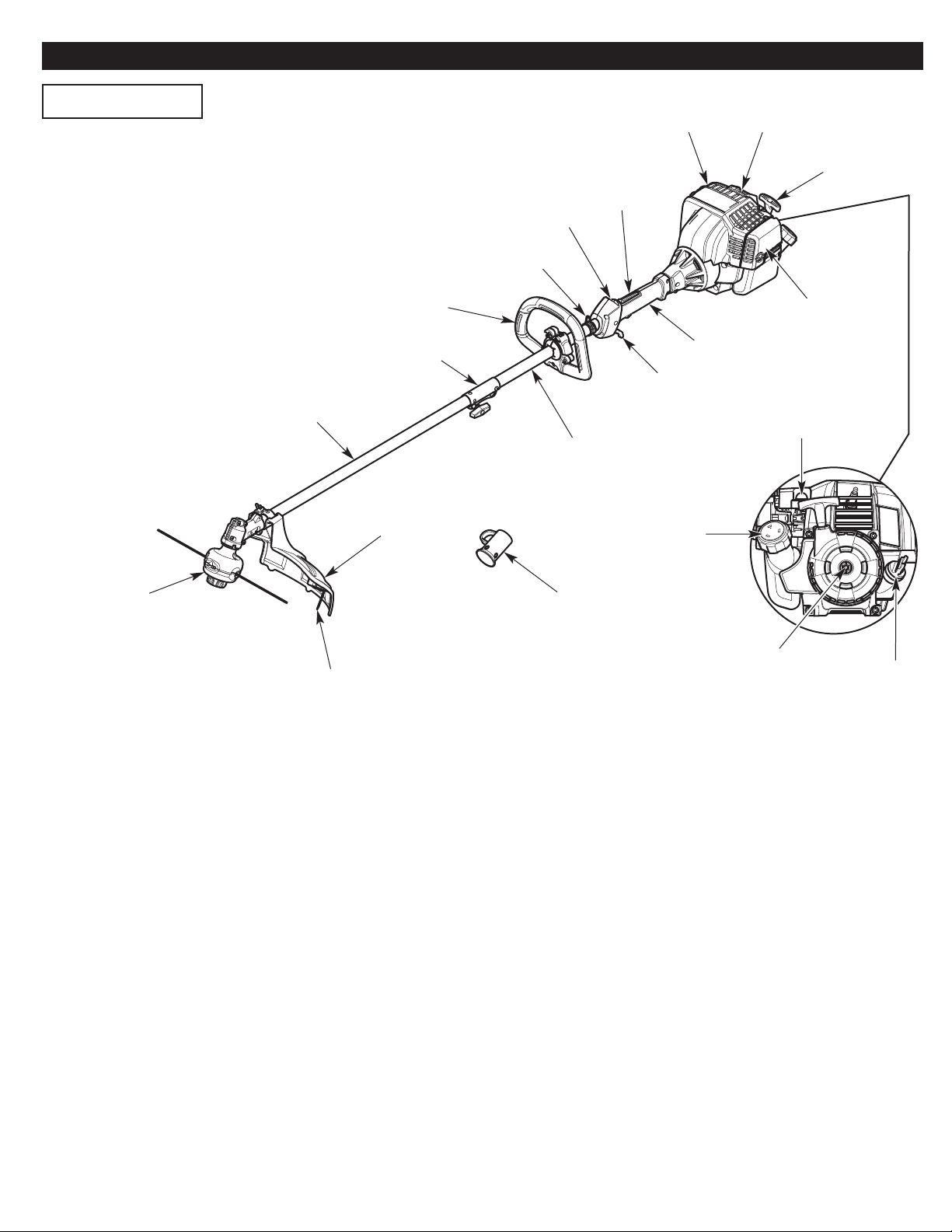
KNOW YOUR UNIT
Spark PlugMuffler
Starter
Rope Grip
Throttle
Lockout
On/Off Switch
Shoulder Strap
/ Harness Loop
ASSEMBLY TOOLS REQUIRED
• Flat-head or T-20 Torx® Screwdriver
Lower Shaft
Housing
Cutting Head
Handle
Coupler
Cutting Head
Shield
Line Cutting Blade
Air Filter
Cover
Shaft Grip
Throttle
Control
Primer Bulb
Upper Shaft
Housing
Fuel Cap
Hanger Cap
Speed Start™ Port
Oil Fill Plug
6

Model No. 316.74097*
APPLICATIONS
As a trimmer:
• Cutting grass and light weeds
• Edging
• Decorative trimming around trees, fences, etc.
Other optional attachments may be used with this unit.
ASSEMBLY TOOLS REQUIRED
• Flat-head Screwdriver
Handle
Coupler
On/Off Switch
Shoulder Strap
/ Harness Loop
Throttle
Lockout
Muffler
Spark Plug
Starter
Rope Grip
Air Filter
Cover
Shaft Grip
Throttle
Control
Lower Shaft
Housing
Cutting Head
Shield
Cutting Head
Line Cutting Blade
Upper Shaft
Housing
Hanger Cap
Primer Bulb
Fuel Cap
Speed Start™ Port
Oil Fill Plug
SPECIFICATIONS
Engine Type . . . . . . . . . . . . . . . . . . . . . . . . . . . . . . . . . . . . . . . . . . . . . . . . . . . . . . . . . . . . . . . . . . . . . . . . . . . . . . . . . . . . . . . Air-Cooled, 4-Cycle
Displacement (Model No. 316.74093*) . . . . . . . . . . . . . . . . . . . . . . . . . . . . . . . . . . . . . . . . . . . . . . . . . . . . . . . . . . . . . . . . . . . 32 cc (1.95 cu. in.)
Displacement (Model No. 316.74097*) . . . . . . . . . . . . . . . . . . . . . . . . . . . . . . . . . . . . . . . . . . . . . . . . . . . . . . . . . . . . . . . . . . . 30 cc (1.83 cu. in.)
Spark Plug Gap. . . . . . . . . . . . . . . . . . . . . . . . . . . . . . . . . . . . . . . . . . . . . . . . . . . . . . . . . . . . . . . . . . . . . . . . . . . . . . . . . . . . 0.025 in. (0.635 mm)
Spark Plug . . . . . . . . . . . . . . . . . . . . . . . . . . . . . . . . . . . . . . . . . . . . . . . . . . . . . . . . . . . . . . . . . . . . . . . . . Champion® RDZ4H or equivalent plug
Lubrication . . . . . . . . . . . . . . . . . . . . . . . . . . . . . . . . . . . . . . . . . . . . . . . . . . . . . . . . . . . . . . . .
Crankcase Oil Capacity . . . . . . . . . . . . . . . . . . . . . . . . . . . . . . . . . . . . . . . . . . . . . . . . . . . . . . . . . . . . . . . . . . . . . . . . . . . . . . . . . 2.37 oz. (70 ml)
Fuel Tank Capacity . . . . . . . . . . . . . . . . . . . . . . . . . . . . . . . . . . . . . . . . . . . . . . . . . . . . . . . . . . . . . . . . . . . . . . . . . . . . . . . . . . . . . . 12 oz. (355 ml)
Approximate Unit Weight (No fuel) . . . . . . . . . . . . . . . . . . . . . . . . . . . . . . . . . . . . . . . . . . . . . . . . . . . . . . . . . . . . . . . 13.5 - 14.5 lbs. (6.1 - 6.6 kg)
Trimmer Mechanism. . . . . . . . . . . . . . . . . . . . . . . . . . . . . . . . . . . . . . . . . . . . . . . . . . . . . . . . . . . . . . . . . Bump Head or Fixed-Line Cutting Head
Trimming Line (Fixed-Line Cutting Head). . . . . . . . . . . . . . . . . . . . . . . . . . . . . . . . . . . . . . . . . . . . . . . . . . Hassle Free™ XTRA QUIET Spiral Line
Trimming Line Diameter (Bump Head) . . . . . . . . . . . . . . . . . . . . . . . . . . . . . . . . . . . . . . . . . . . . . . . . . . . . . . . . . . . . . . . . . . . 0.095 in. (2.41 mm)
Trimming Line Diameter (Fixed-Line Cutting Head) . . . . . . . . . . . . . . . . . . . . . . . . . . . 0.110 in.
Cutting Path Diameter. . . . . . . . . . . . . . . . . . . . . . . . . . . . . . . . . . . . . . . . . . . . . . . . . . . . . . . . . . . . . . . . . . . . . . . . . . . . . . . . . . . 18 in. (45.7 cm)
. . . . . . . . . . . . . . . . . . . . . . . . . . . . . . . SAE 30 Oil
(2.79 mm) Medium or 0.130 in. (3.30 mm) Larg
e
All specifications are based on the latest product information available at the time of printing. We reserve the right to make changes at any
time without notice.
7

ASSEMBLY
INSTALLING THE CUTTING HEAD SHIELD
WARNING:
operate the unit without the cutting head shield in place.
1. Remove the wing nut and washer from the cutting head shield.
2. Insert the short tab (the one without a hole) on the mount
bracket into the slot on the cutting head shield (Fig. 1).
3. Rotate the cutting head shield until the bolt on the cutting head
shield protrudes through the hole on the mount bracket (Fig. 1).
4. Place the washer onto the bolt (Fig. 2).
5. Scr
ew the wing nut onto the bolt until the cutting head shield is
irmly in place (Fig. 2).
f
To prevent serious personal injury, never
Bolt
Cutting Head
Shield
Bolt
Hole
Mount Bracket
Tab
Slot
Fig. 1
Wing Nut
Washer
INSTALLING AND ADJUSTING THE HANDLE
MODEL NO. 316.74093*
Installing the Handle
1. Place a ball half on each side of the upper shaft housing (Fig. 3).
Align each tab with its corresponding slot on the opposite ball
half (Fig. 3). Hold the two halves together. Make sure the ball is
positioned beyond the end of the safety label (Fig. 3).
2. Carefully push the rear handle bracket onto the upper shaft
housing (F
ig. 4). Make sure
the ball and the shaft grip (Fig. 4).
3. Push the rear handle bracket onto the back of the ball and hold
it in place (Fig. 5).
4. Carefully maneuver the front handle bracket over the coupler
and push it onto the front of the ball (Fig. 5). Hold the front and
rear handle brackets together.
5. Insert a nut into one of the hexagonal recesses in the back of
th
ar handle bracket (Fig. 6). Make sure the round side of the
e re
nut faces outward. Hold the nut in place with a finger. Insert a
bolt into the corresponding hole in the front handle bracket (Fig.
6). Tighten the bolt with a flat-head or T20 Torx® screwdriver.
Repeat this step until all four (4) bolts are securely installed.
6. Push the latch pin completely into the small hook on the handle
(Fig. 7). Lift
the latch lever up and push it toward
(Fig. 7). Push the latch loop over the large hook (Fig. 7).
7. Hold the unit in the operating position (Fig. 21). Move the handle
up or down the upper shaft housing to a comfortable location
(Fig. 8). Make sure the handle is positioned beyond the end of
the safety label (Fig. 8).
the rear handle bracket is between
the large hook
Upper Shaft
Housing
Upper Shaft
Housing
Ball Half
Slot
Fig. 2
Tab
Safety
Label
Ball Half
Fig. 3
Ball
Shaft Grip
Rear
Handle
Bracket
Fig. 4
8
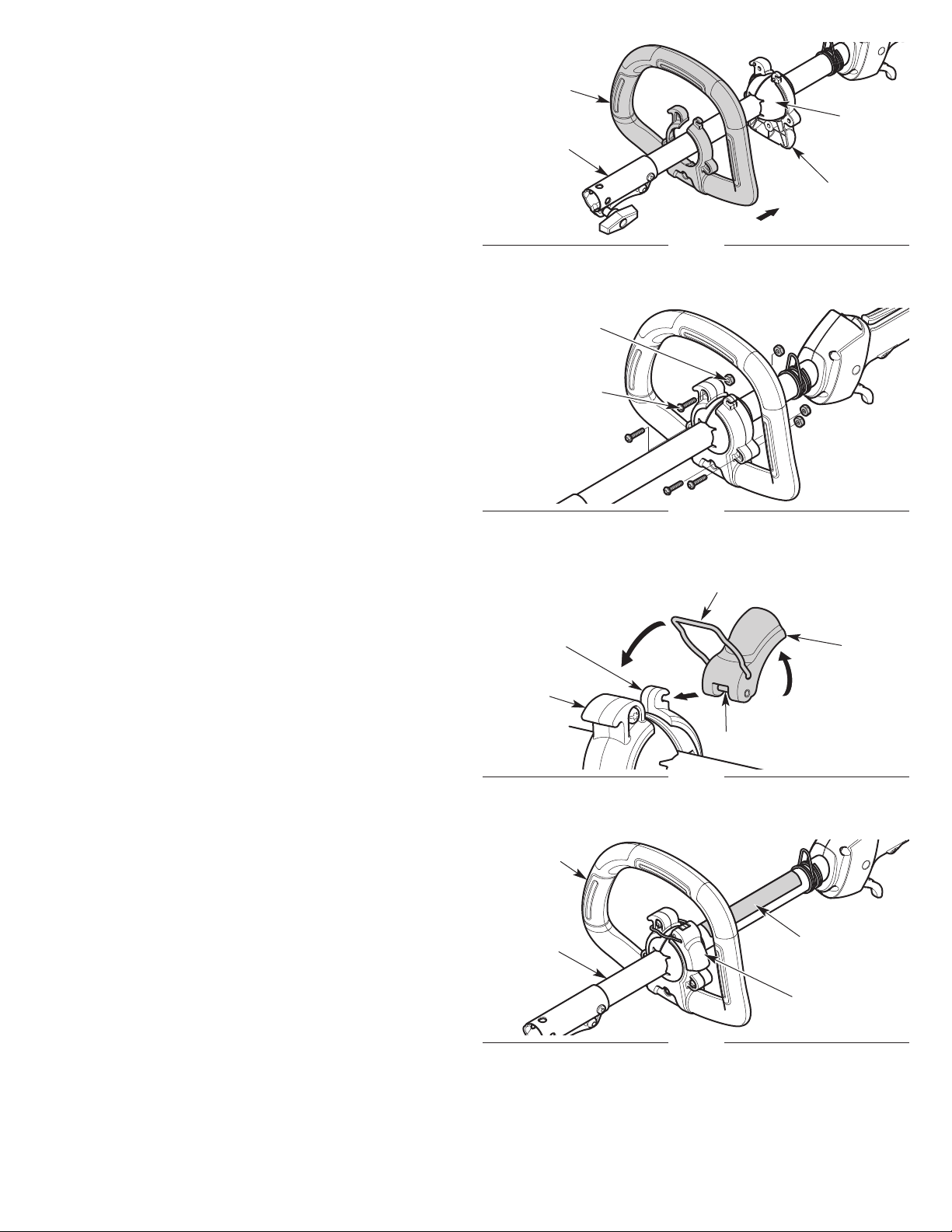
8. Tilt the handle to the desired position.
9. Flip the latch lever down to secure the handle.
Adjusting the Handle
If the handle requires adjustment:
1. Flip the latch lever up to loosen the handle (Fig. 8).
2. Hold the unit in the operating position (Fig. 21). Move the handle
up or down the upper shaft housing to a comfortable location
(Fig. 8). Make sure the handle is positioned beyond the end of
the safe
. Tilt the handle to the desired position.
3
ty label (Fig. 8).
4. Flip the latch lever down to secure the handle.
Front
Handle
Bracket
Ball
Coupler
Rear
Handle
Bracket
Fig. 5
Nut (x4)
Bolt (x4)
Small
Hook
Large
Hook
Handle
Upper Shaft
Housing
Fig. 6
Latch Loop
Latch
Lever
Latch Pin
Fig. 7
Safety Label
Latch Lever
Fig. 8
9

INSTALLING AND ADJUSTING THE HANDLE
MODEL NO. 316.74097*
Handle
Installing the Handle
1. Push the handle down onto the upper shaft housing (Fig. 9).
Make sure the bolt hole faces to the right (Fig. 9).
2. Insert the bolt into the bolt hole and push it through (Fig. 9).
Tighten the bolt with a flat-head screwdriver, but do not tighten
the bolt completely .
3. Hold the unit in the operating position (Fig. 21). Mov
p or down the upper shaft housing to a comfortable location
u
e the handle
(Fig. 9). Make sure the handle is positioned beyond the end of
the safety label (Fig. 9).
4. Tighten the bolt with a flat-head screwdriver until the handle is
secure.
Adjusting the Handle
If the handle requires adjustment:
1. Loosen the bolt with a flat-head screwdriver (Fig. 9).
2. Hold the unit in the operating position (Fig. 21). Mov
e the handle
up or down the upper shaft housing to a comfortable location
(Fig. 9). Make sure the handle is positioned beyond the end of
the safety label (Fig. 9).
3. Tighten the bolt with a flat-head screwdriver until the handle is
secure.
Safety Label
Upper Shaft
Housing
Bolt Hole
Bolt
Fig. 9
10

INSTALLING AND REMOVING THE ATTACHMENT
The coupler enables the use of various optional attachments.
WARNING:
Before using any attachment, read and
understand the manual that came with the attachment.
Follow all safety information contained within.
WARNING:
To avoid serious personal injury and
damage to the unit, shut the unit off before removing or
installing an attachment.
Installing the Attachment
1. Remove the hanger cap from the attachment. Keep the hanger
cap for use when storing the attachment. If present, remove the
gray spacer from the coupler.
2. Set the unit on a flat, level surface.
3. Turn the knob counterclockwise to loosen the coupler (Fig. 10).
4. Align the releas
e button with the guide re
cess (Fig. 12).
5. Push the attachment straight into the coupler (Fig. 11) until the
release button snaps firmly into the primary hole (Fig. 12).
6. Turn the knob clockwise to tighten the coupler (Fig. 10).
WARNING:
Before operating the unit, make sure the
release button is fully snapped into the primary hole and the
knob is securely tightened.
WARNING:
Unless specified otherwise, the release
button should be snapped into the primary hole only. Using
the wrong hole could lead to personal injury or damage to
the unit.
Tighten
Coupler
Loosen
Knob
Fig. 10
Attachment
Fig. 11
Removing the Attachment
1. Set the unit on a flat, level surface.
2. Turn the knob counterclockwise to loosen the coupler (Fig. 10).
3. Press and hold the release button (Fig. 12)
. Pull the attachment straight out of the coupler (Fig. 11).
4
.
Primary Hole
Release Button
Guide Recess
Fig. 12
11
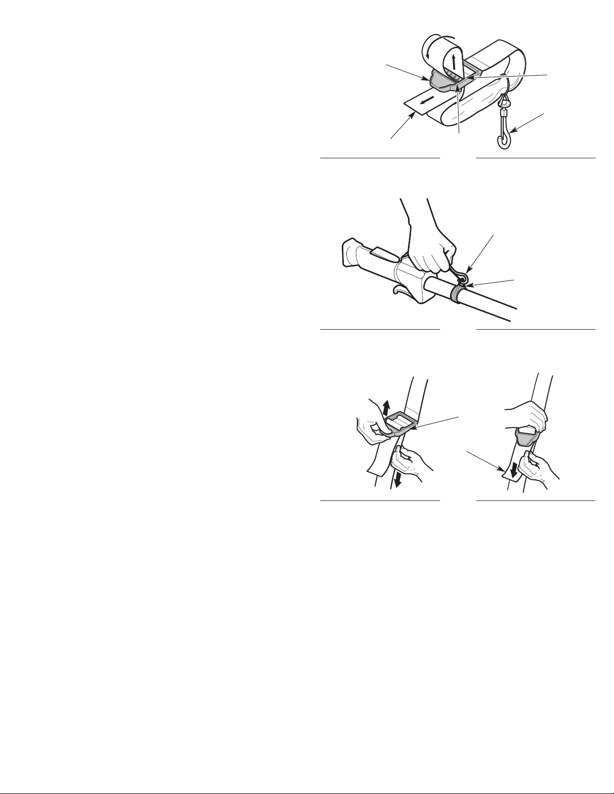
INSTALLING THE SHOULDER STRAP (OPTIONAL)
1. Push the strap up through the center slot in the buckle (Fig. 13).
2. Bend the strap over and push it down through the lower slot in
the buckle (Fig. 13).
3. Put the shoulder strap over the operator’s head and onto the left
shoulder.
4. Start the unit. Refer to Starting and Stopping.
5. Snap the clip onto the shoulder strap / harness loop (Fig. 14).
6. Adjust the sho
uckle up to loosen the shoulder strap. Pull the strap down to
b
tighten the shoulder strap.
ulder strap to fit the operator (Fig. 15). Pull the
Buckle
Strap
Center
Slot
Clip
Lower Slot
Fig. 13
Clip
Shoulder Strap
/ Harness Loop
Fig. 14
Buckle
Strap
Fig. 15
12

OIL AND FUEL
USING THE RIGHT OIL
Use a high-quality SAE 30 weight oil. DO NOT use dirty oil. Failure
to use clean oil of the correct type can cause premature engine
wear and failure.
ADDING OIL: INITIAL USE
WARNING:
CAUSE SERIOUS PERSONAL INJURY. Check the oil level
before each use. The importance of maintaining the proper
oil level cannot be overemphasized. Change the oil
according to the Maintenance Schedule.
NOTE: This unit was shipped without oil in the crankcase. Oil must
be added before starting the unit.
NOTE: This unit comes with a 2.37 fluid oz. (70 ml) container of oil.
1. Set the unit on a flat, level surface.
2. Unscrew the oil fill plug (Fig. 16).
3. Pour the entire container of oil into the oil fill hole (Fig. 16). DO
NOT overfill. Refer to Checking the Oil Level.
NOTE: Never add
engine. DO NOT mix oil with gasoline.
4. Wipe up any oil that may have spilled.
5. Make sure the O-ring is in place on the oil fill plug (Fig. 16).
6. Reinstall the oil fill plug.
OVERFILLING THE CRANKCASE MAY
oil to the fuel tank. This unit has a four-
cycle
USING THE RIGHT FUEL
The use of old fuel is the most common cause of performance
problems. Use only fresh, clean unleaded gasoline.
NOTE: This unit has a four-cycle engine. DO NOT mix oil with gasoline.
Definition of Blended Fuels
Today's fuels are often a blend of gasoline and oxygenates such as
ethanol, methanol or MTBE (ether). Alcohol-blended fuel absorbs
water. As little as 1% water in the fuel can ma
eparate, forming acids when stored. ALWAYS use fresh fuel (less
s
than 30 days old).
NOTE: Dispose of old fuel according to federal, state and local
regulations.
Using Blended Fuels
If using a blended fuel:
• Always use fresh unleaded gasoline
• Use the fuel additive STA-BIL
CAUTION:
It has been proven that fuel containing greater than 10%
ethanol will likely damage this engine and void the warranty.
Using Fuel Additives
Use a fuel additive, such as STA-BIL Fuel Stabilizer or an
equivalent, to inhibit corro
oz. (23 ml) of fuel additive per gallon of fuel, according to the
instructions on the container. NEVER add fuel additives directly to
the unit's fuel tank.
DO NOT USE E85 FUEL IN THIS UNIT.
®
or an equivalent
sion and minimize gum deposits. Add 0.8
ke fuel and oil
Oil Fill Plug
O-Ring
Oil Fill Hole
Fig. 16
FUELING THE UNIT
WARNING:
vapors may explode. Always stop the engine and allow it
to cool before filling the fuel tank. Do not smoke while
filling the tank. Keep sparks and open flames at a distance
from the area.
WARNING:
from fuel spray. Never operate the unit without the fuel cap
securely in place.
WARNING:
area. Wipe up any spilled fuel immediately. Avoid creating
a source of ignition for spilled fuel. Do not start the engine
until fuel vapors dissipate.
1. Position the unit with the fuel cap facing up.
2. Slowly remove the fuel cap.
3. Place the fuel container spout into the fuel tank fill hole and fill
the tank.
NOTE: Do not overfill the tank.
4. Wipe up any fuel that may have spilled.
5. Reinstall the fuel cap.
6. Move the unit at least 30 ft. (9.1 m) from the fuel container and
the fueling site before starting the engine.
Gasoline is extremely flammable. Ignited
Remove the fuel cap slowly to avoid injury
Add fuel in a clean, well-ventilated outdoor
13

STARTING AND STOPPING
WARNING:
Operate this unit only in a well-ventilated
outdoor area. Carbon monoxide exhaust fumes can be
lethal in a confined area.
WARNING:
Avoid accidentally starting the unit. To avoid
serious injury, the operator and the unit must be in a stable
position when pulling the starter rope (Fig. 19).
STARTING INSTRUCTIONS
1. Check the oil level. Refer to Checking the Oil Level.
2. Fill the fuel tank. Refer to Fueling the Unit.
NOTE: There is no need to turn the unit on. The On/Off switch is in
the On ( I ) position at all times (Fig. 17).
3
. Slowly press and release the primer bulb 10 times (Fig. 18).
4. Crouch in the starting position (Fig. 19).
NOTE: PRESS and HOLD the throttle lockout, then SQUEEZE and
HOLD the throttle control for ALL further steps.
NOTE: To prevent the throttle control from being squeezed
accidentally, this unit has a throttle lockout. The throttle control
cannot be squeezed unless the throttle lockou
. Press and hold the throttle lockout. Squeeze and hold the
5
throttle control (Fig. 17). Pull the starter rope with a controlled
and steady motion 5 times to start the engine (Fig. 19).
NOTE: This unit uses the INCREDI-PULL™ starting system, which
significantly reduces the effort required to start the engine.
6. Install the shoulder strap (optional). Refer to Installing the
Shoulder Strap.
t is also engaged.
On/Off Switch
(I = On / O = Off)
Throttle
Lockout
Throttle Control
Fig. 17
Primer Bulb
Fig. 18
IF... the engine does not start, begin the starting procedure with step 3.
IF... the engine fails to start after 3 attempts: Press and hold the throttle
lockout. Squeeze and hold the throttle control. Pull the starter rope
with a controlled and steady motion until the unit starts.
IF... the engine stops while the throttle control is squeezed, begin
the starting procedure with step 3.
IF THE ENGINE IS HOT.
egin the starting procedure with step 3.
.. b
STOPPING INSTRUCTIONS
1. Release the throttle control and allow the engine to idle.
2. Press and hold the On/Off switch in the Off (O) position until the
engine comes to a complete stop (Fig. 17).
Starter Rope Grip
Throttle Control
Starting
Position
Fig. 19
14

USING THE SPEED START™ ACCESSORY
This unit can be started with an optional Speed Start™ accessory
(items sold separately). Please refer to the Speed Start™ accessory
operator’s manual for the proper use of this feature.
Please contact your local Craftsman retailer, call 1-888-331-4569 or
visit www.craftsman.com for more information.
STARTING INSTRUCTIONS
1. Check the oil level. Refer to Checking the Oil Level.
2. Fill the fuel tank. Refer to Fueling the Unit.
NOTE: There is no need to turn the unit on. The On/Off switch is in
the On ( I ) position at all times (Fig. 17).
3. Slowly press and release the primer bulb 10 times (Fig. 18).
4. Crouch in the starting position (Fig. 19).
5. Insert the Speed Start™ accessory into the Speed Start™
Fig. 20). Refer to the Operation section of the Speed Start™
(
accessory operator’s manual.
NOTE: PRESS and HOLD the throttle lockout, then SQUEEZE and
HOLD the throttle control for ALL further steps.
NOTE: To prevent the throttle control from being squeezed
accidentally, this unit has a throttle lockout. The throttle control
cannot be squeezed unless the throttle lockout is also engaged.
6. Press and hold th
throttle control (Fig. 17). Run the Speed Start™ accessory in
intervals no longer than 2 seconds each until the unit starts.
7. Remove the Speed Start™ accessory from the unit.
8. Install the shoulder strap (optional). Refer to Installing the
Shoulder Strap.
ttle lockout. Squeeze and hold the
e thro
port
SPEED START ACCESSORIES
Item No. Description
316.85951 . . . . . . . . . . . . . . . . . . . . . . . . . . . . . .Plug-In Power Start
316.85952 . . . . . . . . . . . . . . . . . . . . . . . . . . . . . . . . . .
316.85953 . . . . . . . . . . . . . . . . . . . . . . . . . . . . .Cordless Power Start
Fig. 20
Power Bit Start
Speed Start™
Port
IF... the engine does not start, begin the starting procedure with step 3.
IF... the engine fails to start afte
throttle lockout. Squeeze and hold the throttle control. Run the
Speed Start™ accessory in intervals no longer than 2 seconds
each until the unit starts.
IF... the engine stops while the throttle control is squeezed, begin
the starting procedure with step 3.
IF THE ENGINE IS HOT... begin the starting procedure with step 3.
r 3 attempts: Pre
ss and hold the
STOPPING INSTRUCTIONS
1. Release the throttle control and allow the engine to idle.
2. Press and hold the On/Off switch in the Off (O) position until the
engine comes to a complete stop (Fig. 17).
15
 Loading...