

Page 1

OWNEirS GUIDE
AMERICAN AMERICAN
MADE OWNED
OUTDOOR POWER EQUIPMENT
Important: Read Safety Rules and Instructions Carefully
REAR TINE
TILLER
Model 406
(With Reverse Drive)
WARNING: This unit is equipped with an internal combustion engine and should not be used on or near any
unimproved forest-covered, brush-covered or grass-covered land unless the engine’s exhaust system is equipped
with a spark arrester meeting applicable local or state laws (if any). If a spark arrester is used, it should be
maintained in effective working order by the operator.
In the State of California the above is required by law (Section 4442 of the California Public Resources Code).
Other states may have similar laws. Federal laws apply on federal lands. A spark arrester for the muffler is avail
able through your nearest engine authorized service dealer or contact the service department, P.O. Box 368022,
Cleveland, Ohio 44136-9722.
MTD PRODUCTS INC • P.O. BOX 368022 • CLEVELAND, OHIO 44136-9722
PRINTED IN U.S.A. FORM NO. 770-8563J
Page 2

INDEX
Safe Operation Practices
Assembly...................................................................... 3
Controls
Operation...................................................................... 9
How To Use Your Tiller
........................................................................
...........................................
................................................
IMPORTANT
THIS SYMBOL POINTS OUT IMPORTANT SAFETY INSTRUCTIONS WHICH, IF NOT FOLLOWED, COULD ENDANGER THE
PERSONAL SAFETY AND/OR PROPERTY OF YOURSELF AND OTHERS. READ AND FOLLOW ALL INSTRUCTIONS IN THIS
A
MANUAL BEFORE ATTEMPTING TO OPERATE YOUR TILLER. FAILURE TO COMPLY WITH THESE INSTRUCTIONS MAY
RESULT IN PERSONAL INJURY. WHEN YOU SEE THIS SYMBOL- ^ HEED ITS WARNING.
Your tiller was built to )e operated according to the rules for safe operation in this manual. As with
DANGER: type of power equi )ment, carelessness or error on the part of the operator can result in serious
A
1. It is suggested that this manual be rt ad in its
entirety before attempting to assemble cr operate
this unit. Keep this manual in a safe Diace for
future and regular reference and for ordering
replacement parts.
2. Your tiller is a precision piece of powar equip
ment, not a plaything. Therefore, axercise
extreme caution at ail times.
3. Read this owner’s manual carefully. Be horoughly familiar with the controls and the prof er use of
the equipment.
4. Never allow children to operate a power tiller.
Only persons well acquainted with thes a rules of
safe operation should be allowed to use your
tiller.
5. No one should operate this unit while ir toxicated
or while taking medication that impairs tfie senses
or reactions.
6. Keep the area of operation clear of all persons,
particularly small children and pets.
7. Do not operate equipment when barefoot or
wearing open sandals. Always wear s jbstantial
footwear.
8. Do not wear loose fitting clothing that could get
caught on the tiller.
9. Do not start the engine unless the shift ever is in
the neutral (N) position.
10. Do not stand in front of the tiller while slarting the
engine.
11. Do not place feet and hands on or neai the tines
when starting the engine or while the engine is
running.
12. Never attempt to make a wheel or depth bar
adjustment while the engine is running.
13. Do not leave the tiller unattended with t ie engine
running.
injury. If you violate an f of these rules, you may cause serious injury to yourself or others.
2
8
9
Adjustments
Lubrication
Maintenance
Off-Season Storage
Trouble Shooting Guide
................................................................
..................................................................
................................................................
....................................................
.............................................
RULES FOR SAFE OPERATION
Do not walk in front of the tiller while the engine
14.
is running.
Check the fuel before starting the engine.
15.
Gasoline is an extremely flammable fuel. Do not
fill gasoline tank indoors, while the engine is run
ning, or while the engine is still hot. Replace
gasoline cap securely, and wipe off any spilled
gasoline before starting the engine as it may
cause a fire or explosion.
Do not run the engine while indoors. Exhaust
16.
gases are deadly poisonous.
Be careful not to touch the muffler after the
17.
engine has been running. It is hot.
Do not change the engine governor settings or
18.
overspeed the engine. Excessive engine speeds
are dangerous.
Before any maintenance work is performed or
19.
adjustments are made, remove the spark plug
wire and ground it on the engine block for added
safety.
Use caution when tilling near buildings and
20.
fences. Rotating tines can cause damage or
injury.
Before attempting to remove rocks, bricks and
21.
other objects from tines, stop the engine and be
sure the tines have stopped completely.
Disconnect the spark plug wire and ground to
prevent accidental starting.
Check the tine and engine mounting bolts at fre
22.
quent intervals for proper tightness.
Keep all nuts, bolts and screws tight to be sure
23.
the equipment is in safe working condition.
Never store the equipment with gasoline in the
24.
tank inside of a building where fumes may reach
an open flame or spark. Allow the engine to cool
before storing in any enclosure.
10
12
12
14
15
A
Page 3
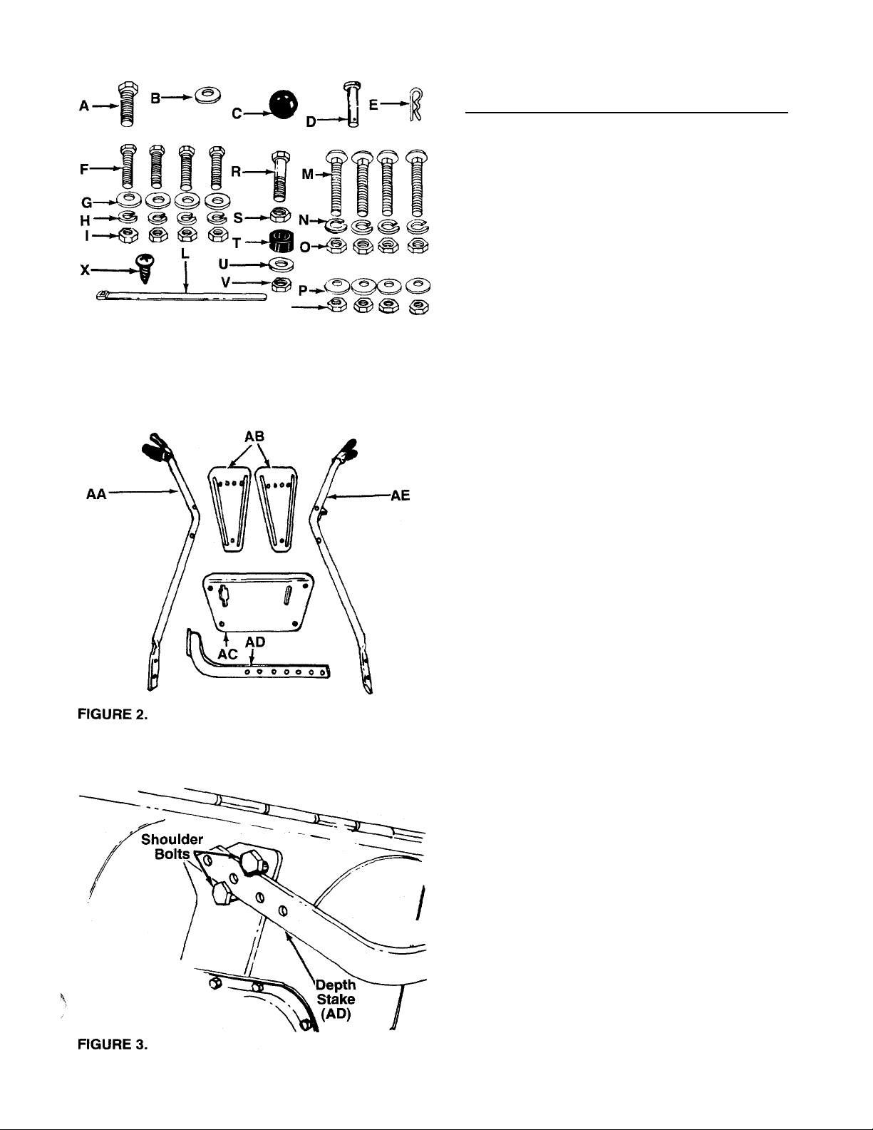
FIGURE 1.
ASSEMBLY INSTRUCTIONS
IMPORTANT: This unit is shipped WITHOUT GASO
LINE or OIL. After assembly, see separate engine
manual for proper fuel and engine oil recommenda
tions.
NOTE: Left and right is determined from the opera
tor’s position, standing behind the tiller.
-Contents of Hardware Pack: (See Figure 1)
(Part numbers are shown in parentheses.)
A
B
C
D
E
F
G
H
I
L
M
N
O
P
Q
R
S
T
u
V
w
X
-Loose Parts in Carton: (See figure 2)
(Part numbers are shown in parentheses.)
AA (1) Handle—R.H. (749-0642A)
AB
AC
AD
AE
1. Remove tiller, loose parts and hardware pack
2. Extend the control cables attached to the tiller
Hex Bolt 3/8-16 X 3/4" Long (710-0216)
(1)
Flat Washer 3/8" I.D. (736-0117)
(1)
Ball Knob (720-0165)
(1)
Clevis Pin (711-0415)
(1)
Hairpin Cotter (714-0149B)
(1)
Hex Bolts 3/8-16 X 1.0" Long (710-0253)
(4)
Belleville Washers 3/8" I.D. (736-0105)
(4)
Lock Washers 3/8" I.D. (736-0169)
(4)
Hex Nuts 3/8-16 Thread (712-0798)
(4)
Cable Ties (725-0157)
(2)
Carriage Bolts 5/16-18 x 1.75" Long
(4)
(710-0458)
Lock Washers 5/16" I.D. (736-0119)
(4)
Hex Nuts 5/16-18 Thread (712-0267)
(4)
Belleville Washers 5/16" I.D. (736-0242)
(4)
Hex Nuts 5/16-18 Thread (712-0267)
(4)
Hex Bolt 1/4-28 x .75" Long (710-0412)
(1)
Hex Lock Nut 1/4-28 Thread (712-0117)
(1)
Rubber Washer (735-0126)
(1)
Flat Washer 5/16" I.D. x 7/8" O.D. (736-0159)
(1)
Hex Lock Nut 5/16-18 Thread (712-0158)
(1)
Reverse Drive Clutch Lever (Not Shown—
(1)
747-0517, Grip—720-0143)
Self-Tapping Screw (710-0779A)
(1)
Side Shields (15390)
(2)
Handle Panel (784-0271)
(1)
Depth Stake Assembly (14992)
(1)
Handle—L.H. (749-0643A)
(1)
from carton. Make certain all parts and literature
have been removed from the carton before the
carton is discarded.
and place on the floor. Be careful not to bend or
kink the cables.
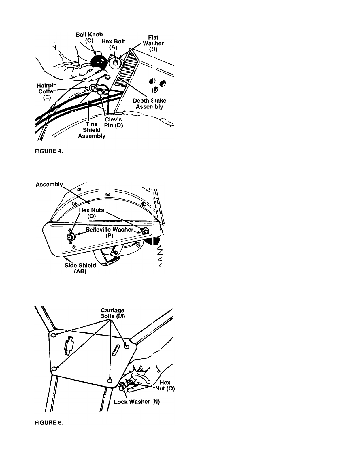
DEPTH STAKE INSTALLATION
1. Raise the tine shield hinge flap assembly. Insert
the depth stake assembly (AD) between the two
shoulder bolts and up through the tine shield
i
-----
assembly as shown in figure 3. Depth stake
points toward the rear of the unit.
NOTE: For clarity, figure 3 was taken with tiller raised
on end. It is not necessary to raise the tiller.
Page 4
I I
2. Insert clevis pin (D) through the tine shield and
depth stake assemblies. Secure with hairpin cot-
— ter (E). See figure 4.
3. Insert hex bolt (A) into the upper hole of the depth
stake assembly. Place flat washer (B) onto the
hex bolt and thread ball knob (C) onto the hex
bolt. See figure 4. Tighten securely.
End Cover
FIGURE 5.
SIDE SHIELD INSTALLATION
Mount side shields (AB) over the weld bolts on the
end cover assemblies. Secure with belleville washers
(P) and hex nuts (Q). Crowned side of washers go
-against the hex nuts. See figure 5.
HANDLE ASSEMBLY
1. Attach the handle panel to the handles using car
riage bolts (M), lock washers (N) and hex nuts
------
(O). See figure 6. Do not tighten.
NOTE: To align the holes in the handle panel and the
handle, it may be necessary to loosen the cable
brackets which are mounted to the back of the han
dles with self-tapping screws.
Page 5
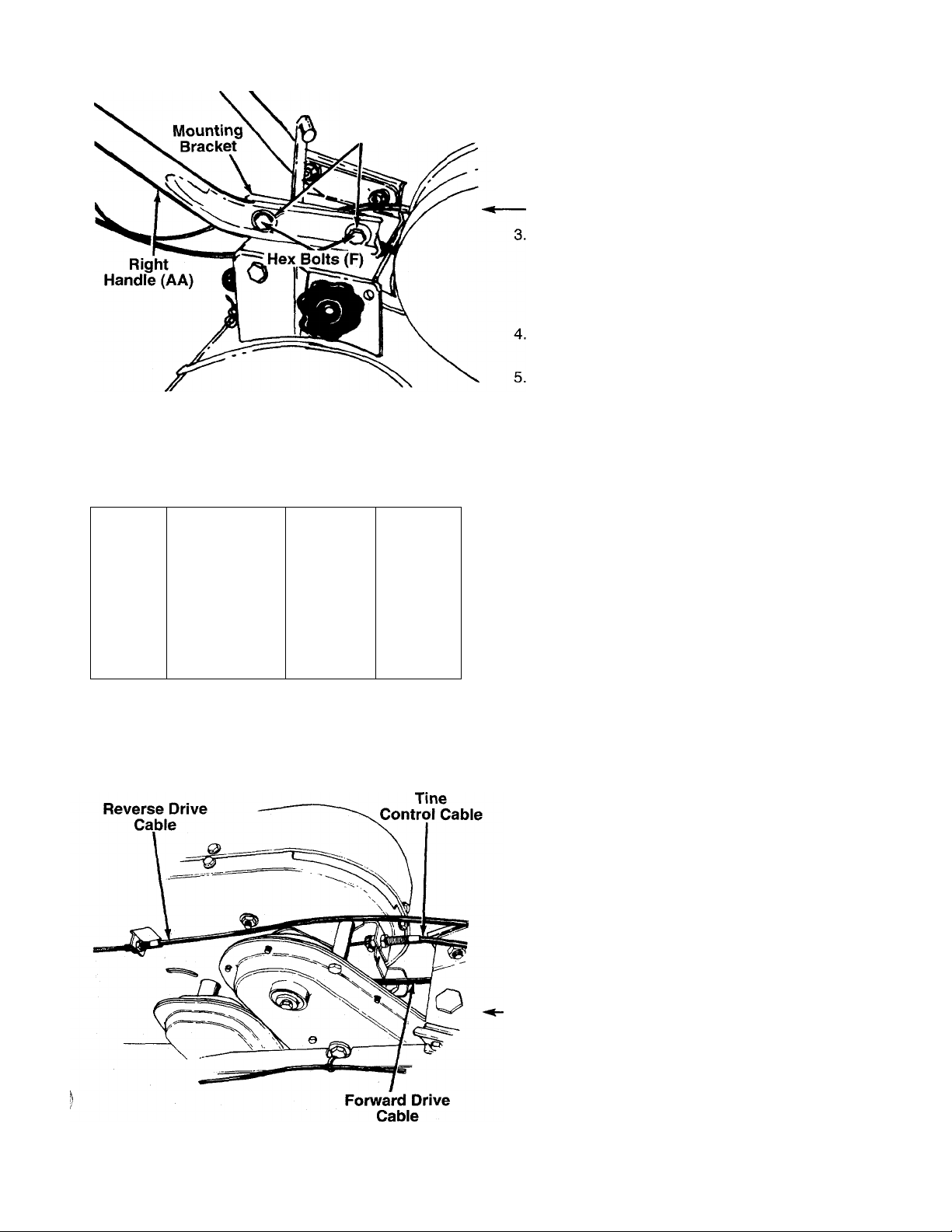
FIGURE 7.
A B
¥
!
Washers (G)
1
Belleville
y
Screw
D \
(X)
2. Place handle assembly in position on the tiller.
Working on one side of the unit, insert one hex
bolt (F) through belleville washer (G) (crowned
side of washer goes against head of bolt), then
through bottom hole of handle and handle mount
ing bracket. Secure loosely with lock washer (H)
-and hex nut (I). See figure 7.
Align the other side of the handle with the handle
mounting bracket. It may be necessary to use
force to spring the handle over the handle mount
ing bracket. Secure loosely with hex bolt,
belleville washer, lock washer and hex nut.
Secure upper hole in handle to handle mounting
bracket (both sides) in the same manner.
Tighten securely all four nuts and bolts which
secure the handles to the handle mounting brack
ets. Then tighten the four nuts at the handle
panel.
THROTTLE CONTROL INSTALLATION
Assemble the throttle control to the handle panel as
follows.
1. Hold the throttle control assembly beneath the
handle panel. Turn the control sideways and
insert the lever up through the wide portion of the
------
slot on the handle panel. See figure 8A.
2. After the end of the lever is through the slot, turn
and then tip the control forward as shown in fig
ure 8B to slide it through the slot.
FIGURE 8.
FIGURE 9.
NOTE: The lever must be all the way to the back of
the control housing as shown in figure 8B.
Push the control back into the slot in the handle
panel and press in place. Be certain the control is
locked securely into the slot.
4.
Secure the throttle control to the handle panel
using the self-tapping screw (X). See figure 8D.
ATTACHING THE CONTROL CABLES
The control cables are already attached to the unit.
The tine control cable and the forward drive cable
have “2” fittings on the loose end. Refer to figure 9 for
cable identification when attaching the cables.
NOTE: Both the drive control cables and the tine con
trol cable are attached to springs, which are hooked
to bolts. If either the cable or spring has come loose in
shipping, it must be reassembled. Refer to page 18,
reference numbers 2, 5, 11, 12, 15 and 17.
Page 6

Tine Control Cable (Attaches to Left Handle)
1. Remove one nut and the lock washer from the
end of the tine control cable. Slip the cable up
through the slot on the cable bracket on the left
handle. Rethread hex nut and lock washer on the
------
end of the cable. See figure 10. Do not tighten at
this time.
2. Hook the “Z” end of tine control cable into the
hole in tine clutch lever.
3. With the clutch lever released (in the “up” posi
tion), adjust the bottom nut at the cable bracket
so there is only a slight amount of slack in the
control wire. Tighten the upper nut against the
bracket. Squeeze the clutch lever against the
handle. The control wire should now be straight.
------
See figure 11.
NOTE: Do not overtighten control wire. Too much ten
sion may cause it to break.
FIGURE 11.
Flat End of
Reverse Clutch
Forward Drive Control Cable
(Attaches to Right Handle)
Attach the forward drive control cable (refer to figure
9) to the right handle in the same manner in which the
tine control cable was attached.
WARNING: Final adjustment of the for
ward and reverse drive cables must be
A
made as instructed in the Final Adjust
ment section before operating the tiller.
Reverse Drive Control Cable
1. Push the flat end of reverse drive clutch lever
through the slot in the handle panel. See figure
--------
12.
2. Attach the end of drive control cable to the upper
hole of reverse drive clutch lever (W), using hex
bolt (R) and hex lock nut (S). See figure 13.
3. Remove one nut and the lock washer from the
end of the reverse drive control cable. Thread the
other hex nut all the way down the cable as far as
-------
it will go as shown in figure 13.
4. Slip the wire on the cable through the inside slot
In the cable bracket as shown in figure 12. Push
the ends of the cable up through the holes in the
bracket. Rethread hex nut and lock washer on the
end of the cable. Do tighten at this time.
5. Place end of reverse drive clutch lever over weld
bolt on handle panel. See figure 12.
Page 7

FIGURE 14.
6. Secure reverse drive clutch lever to weld bolt with
rubber washer (T), flat washer (U) and hex lock
— nut (V). See figure 14. Tighten hex lock nut until
snug. Do not overtighten.
7.
With the reverse drive clutch lever in the neutral
(N) position, adjust the reverse cable as follows.
Adjust the hex nuts at the cable bracket on the
handle panel so that the cable is tight, and the
bolt on the reverse idler pulley is in the center of
the slot (approximately 1" from either end of the
slot) as shown in figure 15.
Secure the cables to the right hand handle with
8
two cable ties (L), one near the top and one near
the bottom of handle. Trim excess ends of cable
ties.
9. Check the adjustment of the drive clutch controls
as follows.
FIGURE 15.
Cable
Bracket
FINAL ADJUSTMENTS
First check the adjustment of the drive clutch controls
with the engine off as follows.
1. Disconnect the spark plug wire from the spark
plug and ground against the engine.
2. Make certain the forward drive and tine clutch
levers are released, and the reverse drive clutch
lever is in the neutral (N) position.
3. Pull the recoil starter rope several times. If the
unit moves forward, adjust the forward cable as
instructed in step A which follows. If the unit
moves backward, adjust the reverse cable as
instructed in step B which follows.
IMPORTANT: Service engine with oil and gasoline
before starting the engine. Refer to the separate
engine manual packed with your tiller.
Now check the adjustment of the drive clutch controls
with the engine running. Place the unit against a solid
object (wall, fence, etc.). With the forward drive clutch
lever and tine clutch lever released and the reverse
drive clutch lever in the neutral position, carefully start
the engine.
WARNING: BE PREPARED TO STOP
ENGINE IMMEDIATELY, as tiller may go
A
in reverse motion.
NOTE: The unit moves faster in reverse than in for
ward.
Page 8

Note which (if any) of the following conditions exist in
your unit. Adjust the cable(s) at the cable brackets by
following the appropriate instructions.
WARNING: Stop the engine before mak
A
A. TILLER HAS FORWARD MOTION with forward
B. TILLER HAS REVERSE MOTION with reverse
C. TILLER DOES NOT HAVE FORWARD MOTION
ing any cable adjustments.
drive clutch lever released. Adjust the forward
cable (right hand handle) by loosening the hex nut
on top of the cable bracket three or four turns,
then tightening the hex nut beneath tha cable
bracket.
drive clutch lever in neutral. Adjust the reverse
cable (beneath the handle panel) by loosening the
nut beneath the cable bracket three or four turns,
then tightening the hex nut on top of the cable
bracket.
with forward drive clutch lever in forward. Adjust
the forward cable by loosening the hex nut beneath
the cable bracket three or four turns, then tighten
ing the hex nut on top of the cable bracket.
D. TILLER DOES NOT HAVE REVERSE MOTION
with the reverse drive clutch lever in reverse.
Adjust the reverse cable by loosening the hex nut
on top of the cable bracket three or four turns, then
tightening the hex nut beneath the cable bracket.
TIRE PRESSURE
The tires on your unit may be over-inflated for ship
ping purposes. Reduce the tire pressure before oper
ating the unit. Recommended operating tire pressure
is approximately 12 p.s.i. (check sidewall of tire for tire
manufacturer’s recommended pressure).
WARNING: Maximum tire pressure under
any circumstances is 30 p.s.i. Equal tire
A
pressure shouid be maintained on both
tires.
CONTROLS
THROTTLE CONTROL
The throttle control lever is located on the right hand
side of handle panel and controls the engints speed.
See figure 16.
1. Start—Push throttle control lever forwarpi (down)
to FAST position.
2. Stop—Pull lever back (upward) to stop th(i engine.
figure 16. Squeeze the lever against the handle to
engage the tines. Release the lever to stop the tines
from turning.
FORWARD DRIVE CLUTCH LEVER
The forward drive clutch lever is located on the left
handle. See figure 16. Squeezing the lever against
the handle engages the forward wheel drive. Release
the lever to stop the forward motion.
REVERSE DRIVE CLUTCH LEVER
The reverse drive clutch lever is located on the left
hand side of handle panel. See figure 16.
The reverse drive clutch lever may be placed in one
of two positions.
1. Neutral (N)—Be certain lever is in neutral position
when starting the engine.
2. Reverse (R)—Raise up on the handles to lift the
tines out of the ground and pull the drive clutch
lever back (upward) slowly to obtain reverse.
Always use caution when using the reverse.
When using reverse, if reverse drive clutch lever
is released it will snap back into neutral (N).
TINE CLUTCH LEVER
The tine clutch lever is located on the left handle. See
NOTE: A/ever engage both the forward and reverse
drive at the same time, or the engine will stall.
Page 9

•V
IMPORTANT: Engine is shipped without oil.
BEFORE STARTING
1. Before operating tiller for the first time or if tines
have been removed and reassembled for any
reason, check to be certain the tines are assem
bled correctly. The sharp edge of the tines must
enter the soil first as shown in figure 17. (Figure
17 illustrates the left hand tines, viewed from the
left hand side of the tiller. Right hand tines rotate
in the same direction as the left hand tines.)
OPERATION
TO START ENGINE
A
1. Place the throttle control lever in START position.
2. Move choke lever to CHOKE position.
NOTE: A warm engine may not require choking.
3.
Stand at side of tiller. Grasp the starter handle
and pull out slowly, until it pulls slightly harder.
Let rope rewind slowly.
4.
Pull starter handle rapidly. Do not allow handle to
snap back. Allow it to rewind slowly while keeping
a firm hold on the starter handle.
5. Repeat steps 3 and 4 until engine starts.
6. As engine warms up and begins to operate even
ly, move choke lever gradually to OFF position. If
engine falters, return to choke position, then slow
ly move to OFF position.
Refer to engine manual for additional engine informa
tion.
WARNING: BE SURE NO ONE IS STAND
ING IN FRONT OF THE TILLER WHILE
THE ENGINE IS RUNNING OR BEING
STARTED.
2. Service engine with oil as instructed in the sep
arate engine manuai packed with your unit.
3. Fill fuel tank with clean, fresh, lead-free, low-lead
or regular grade leaded gasoline.
HOW TO USE YOUR TILLER
WARNING: When operating the tiller for
A
Tilling depth is controlled by the depth stake which
can be adjusted to five different settings. See figure
18. Adjust the side shields as shown in figure 19, as
you adjust the depth stake. Be certain spark plug wire
is disconnected and grounded against the engine.
1. When using the tiller for the first time, use the
the first time, use the depth bar setting
that gives 11/2 inches of tilling depth
(second hole from the top). Refer to fig
ure 18. Use slow speed only.
second adjustment hole from the top (1-1/2” of till
ing depth). See figure 18.
TO STOP ENGINE
1. Move throttle control to OFF position.
2. Disconnect spark plug wire and ground to prevent
accidentally starting while equipment is un
attended.
Page 10

2. When breaking up sod and for shallow cul Jvation,
use the setting which gives 11/2” of tillinj depth
(second hole from the top). Place the side shields
in their lowest position. For further depti, raise
the depth stake and side shields and make one
or two more passes over the area.
3. When tilling loose soil, depth stake may b 3 raised
to its highest position (use bottom adjustment
hole) to give the deepest tilling depth. Raise the
side shields to their highest position.
4. To transport tiller, lower the depth stake [use top
adjustment hole).
To adjust the depth stake, remove the clevis pin and
hairpin cotter. See figure 18. Move the depth stake to
the desired setting.
To adjust the side shields, remove the hex nut and
belleville washer from the front and loosen the rear
nut. See figure 19. Pivot the side shield to the desired
position. Replace hex nut and belleville washer.
Tighten securely.
To operate the tiller;
1. Select the depth stake setting.
2. Start engine as instructed on page 9.
3. Engage either the forward drive clutch lever or
the reverse drive clutch lever.
4. Engage tine clutch lever.
ADJUSTMENTS
WARNING: Disconnect the spark plug
wire and ground against the engine
A
HANDLE ADJUSTMENT
The handle may be placed in one of nine different
positions. The handle may be adjusted to one of three
height positions, and also may be adjusted to be in
line with the tiller, or swung to the left or right so the
operator is not walking in the freshly tilled soil.
To adjust the handle height, remove the hand knob
and locking pin shown in figure 20. Select one of the
three adjustment holes and reassemble.
FIGURE 20.
To adjust the handle position from side to side, loosen
the adjustment handle by turning it counterclockwise
several turns. Pull the adjustment handle backward
and pivot the tiller handle to desired position. Release
and tighten the adjustment handle. See figure 21.
before performing any adjustments,
repairs, or maintenance.
WARNING: Engage wheel driv j before
engaging the tine clutch lever.
NOTE: To transport tiller, do not engage the tine
A
clutch lever. Engage the wheel drive only.
WARNING: Do not push down on the
handles so that the wheels are lifted off
A
For best results, it is recommended the garden be
tilled twice (lengthwise, then widthwise) to pulverize
the soil.
the ground while the tine clutch is
engaged, or the tiller could mc ve back
ward and cause personal injury.
10
Page 11

DEPTH STAKE ADJUSTMENT
To adjust the depth stake, refer to “How To Use Your
V,
Tiller” on pages 9 and 10.
When making either of the above adjustments (a or
b), be certain to recheck the neutral adjustments on
the tiller (steps A and B in first column on page 8).
BELT TENSION ADJUSTMENT
Tine Clutch
Periodic adjustment of the belt tension may be
required due to normal stretch and wear on the belt.
Adjustment is needed if the tines seem to hesitate
while tilling, but the engine maintains the same speed.
To adjust, loosen the hex nuts at the cable bracket on
the handle. See figure 22. With the clutch lever
released as shown in figure 16, adjust the bottom nut
so that there is only a slight amount of slack in the
control wire. Tighten the upper nut against the brack
et.
NOTE: Do not overtighten control wire. Too much ten
sion may cause it to break.
Drive Clutch
if adjustment is needed, refer to final adjustment sec
tion of Assembly instructions.
If through normal operation the belts become
stretched or worn, and there is no adjustment left at
the cable brackets on the handles and handle panel,
the other end of the cables may be adjusted as fol
lows.
a. If the tiller does not have forward motion with the
forward drive clutch lever engaged, adjust the for
ward drive cable by loosening the hex nut in back
of the cable bracket on the tiller a few turns, then
tightening the hex nut in front of the bracket. Refer
to figure 9.
b. If the tiller does not have reverse motion with the
reverse drive clutch lever in reverse, adjust the
reverse cable by loosening the hex nut in front of
the cable bracket on the tiller a few turns, then
tightening the hex nut in back of the bracket. When
correctly adjusted, the reverse idler should be
toward the middle of the slot as shown in figure 15.
CARBURETOR ADJUSTMENT
WARNING: If any adjustments are made
A
Minor carburetor adjustment may be required to com
pensate for differences in fuel, temperature, altitude
or load. If adjustments are needed, refer to the engine
manual packed with the tiller.
NOTE: A dirty air cleaner will cause engine to run
rough. Be certain air cleaner is clean and attached to
the carburetor before adjusting carburetor. Do not
make unnecessary adjustments. Factory settings are
satisfactory for most applications and conditions.
to the engine while the engine is running,
(e.g. carburetor), disengage all clutches
and tines. Keep ciear of ali moving parts.
Be careful of heated surfaces and muf
fler.
THROTTLE CONTROL ADJUSTMENT
To obtain satisfactory engine performance, the engine
throttle control must be adjusted properly. If it is nec
essary to check the engine control adjustments, pro
ceed as follows.
1. Loosen the cable clamp screw. See figure 23.
2. With the throttle control in FAST position and the
cable connected to the adapter lever, push the
cable through the cable clamp in the direction
shown in figure 23 until the adapter lever is as far
up as it will go.
3. Tighten the cable clamp screw.
4. Check that the engine stops when throttle control
is moved to STOP position. If engine does not
stop, loosen the cable clamp screw and readjust
by pulling cable backward slightly until engine
stops. Retighten cable clamp screw.
Adapter
Lever
Cable Clamp
Screw
FIGURE 23.
11
Page 12

LUBRICATION
WARNING: Always stop engine and dis
connect spark plug wire before cleaning,
A
Chain Cases—The chain cases are pre-lu jricated
and sealed at the factory. They require no < becking
unless the chain cases are disassembled. Tci fill with
grease, lay the left half of the chain case on its side.
Add 12 ounces of plastilube #0 grease to the tine
chain case or 10 ounces to the wheel chain case.
Assemble the right half to it. This grease can be
obtained through your nearest authorized dealer.
Order part number 737-0133 (14 oz. tube).
Wheels—Lubricate the wheel bearings with a light oil
after each fifteen hours of operation.
Ciutch Controls—Lubricate the pivot points on the
clutch levers and the cables at least once a season
with light oil. The controls must operate freely in both
directions.
Pivot Points—Lubricate all pivot points and linkages
at least once a season with light oil.
lubricating or doing any kind of v/ork on
tiiler.
usually indicates that the air cleaners should be ser
viced. To service the air cleaner, refer to the separate
engine manual packed with your unit.
The spark plug should be cleaned and the gap reset
once a season. Spark plug replacement is recom
mended at the start of each tilling season; check
engine manual for correct plug type and gap specifi
cations.
CLEANING THE TINE AREA
Clean the underside of the tine shield after each use.
The dirt washes off the tines easier if washed immedi
ately instead of after if dries.
TIRES
Recommended operating tire pressure is approxi
mately 12 p.s.i. (check sidewall of tire for tire manu
facturer’s recommended pressure). Maximum tire
pressure under any circumstances is 30 p.s.i. Equal
tire pressure should be maintained on both tires.
When installing a tire to the rim, be certain rim is
clean and free of rust. Lubricate both the tire and rim
generously. Never inflate to over 30 p.s.i. to seat
beads.
MAINTENANCE
WARNING: Disconnect the spark piug
wire and ground it against the engine
A
IMPORTANT: If for any reason the tines are removed
from the tiller, be certain the tines are reassrsmbled so
that the sharp edge of the tines enter the soil first.
Refer to item number one under “Operation. ’
TROUBLE SHOOTING
Refer to page 15 of this manual for troubk shooting
information.
ENGINE
Refer to the separate engine manual for all engine
maintenance instructions.
Maintain engine oil as instructed in the separate
engine manual packed with your unit. Read and follow
instructions carefully.
Service air cieaner every 25 hours under n Drmal con
ditions. Clean every few hours under extremely dusty
conditions. Poor engine performance and flooding
before performing any repairs o' mainte
nance.
WARNING: Excessive pressure (over 30
A
BELT REPLACEMENT
Your tiller has been engineered with belts made of
special material (Kevlar Tensile) for longer life and
better performance. They should not be replaced with
an off-the-shelf belt.
If belt replacement is required, order belt or belts by
part number from your nearest authorized dealer.
1. Remove belt cover by removing the four self-tap
p.s.i.) when seating beads may cause
tire/rim assembiy to burst with force suf
ficient to cause serious injury.
ping screws. See figure 24.
12
Page 13

2. To remove the tine belt, lift up on the idler pulley,
and slip belt off tine chain case pulley as shown
in figure 25. Remove belt from the two-step
engine pulley.
B. Pull bottom of wire belt keeper out and then
upward, pivoting it away from the forward
engine pulley. See figure 27.
Tine Belt
Idler
Pulley
Two-Step
Engine Pulley
FIGURE 25.
3. To remove the reverse drive belt, lift up on small
idler pulley as shown in figure 26. Slip belt off out
side sheave of wheel chain case pulley. Then
remove belt from two-step engine pulley.
Wheel Chain
FIGURE 27.
C. Lift belt off the forward engine pulley. See fig
ure 28.
D. Remove belt from inside sheave of wheel
chain case pulley.
Wheel Chain
Case Pulley Forward
J3rive Belt Forward
Engine Pulley
FIGURE 26. FIGURE 28.
4. To remove the forward drive belt, proceed as fol
lows.
5. Reassemble new belts, following instructions in
reverse order.
IMPORTANT: When reassembling belts, be certain
A. Loosen (do not remove) the hex nut at the top
of the wire belt keeper.
belts are routed around all belt keeper pins as shown
in figure 29.
13
Page 14

Forward BeltKeoper
Drive Belt Pins
FIGURE 29.
NOTE: If the “V”-idler or flat idler pulleys are removed
for any reason, be sure to install with hub side against
the idler bracket. See figure 30.
Hub
OFF-SEASON STORAGE
If the tiller is to be inoperative for a period longer than
30 days, the following precautions are recommended.
1. Working outdoors, drain all fuel from the fuel tank.
Run the engine until it stops from lack of fuel.
WARNING: DO NOT DRAIN FUEL WHILE
A
2. Drain all the oil from the crankcase (this should
3. Protect the inside of the engine for storage as
4. Clean the exterior of engine and the entire tiller
5. Wipe tines with oiled rag to prevent rust.
NOTE: When storing any type of power equipment in
an unventiiated or metal storage shed, care should be
taken to rustproof the equipment. Using a light oil or
silicone, coat the equipment, especially any springs,
bearings and cables.
SMOKING, OR IF NEAR AN OPEN FIRE.
be done after the engine has been operated and
is still warm) and refill the crankcase with fresh
oil.
instructed in the separate engine manual packed
with your unit.
thoroughly.
FIGURE 30.
6. Store in a clean, dry area. Do not store next to
corrosive materials, such as fertilizer.
14
Page 15

TROUBLE SHOOTING GUIDE
Trouble
Engine fails to start
Engine runs erratic 1. Unit running on CHOKE.
Possible Cause(s) Corrective Action
1. Fuel tank empty, or stale fuel.
2. Throttle control lever not in
starting position.
3. Spark plug wire disconnected.
4. Faulty spark plug.
5. Engine flooded.
2. Spark plug wire loose.
3. Stale fuel.
4. Vent in gas cap plugged.
5. Water or dirt in fuel system.
6. Dirty air cleaner.
7. Carburetor out of adjustment.
Engine overheats 1. Engine oil level low.
2. Air flow restricted.
3. Carburetor not adjusted
properly.
1. Fill tank with clean, fresh gasoline.
2. Move throttle lever to START position.
3. Connect wire to spark plug.
4. Clean, adjust gap or replace.
5. Remove spark plug, dry the plug,
and crank engine with plug removed
and throttle in OFF position. Replace
spark plug, connect wire and resume
starting procedures.
1. Move choke lever to OFF position.
2. Connect and tighten spark plug wire.
3. Fill tank with clean, fresh gasoline.
4. Clear vent.
5. Drain fuel tank. Refill with fresh fuel.
6. Clean air cleaner as instructed in
separate engine manual.
7. Adjust carburetor as instructed in
separate engine manual.
1. Fill crankcase with proper oil.
2. Remove blower housing and clean as
instructed in separate engine manual.
3. Adjust carburetor as instructed in
separate engine manual.
Tines do not engage 1. Foreign object lodged in tines.
2. Tine clevis pin(s) missing.
3. Control cable not adjusted
properly.
4. Belt worn and/or stretched.
Wheels do not engage
NOTE; For repairs beyond the minor adjustments listed above, please contact your local service dealer.
1. Control cable not adjusted
properly.
2. Belt worn and/or stretched.
1. Dislodge foreign object.
2. Replace tine clevis pin(s).
3. Adjust control cable (see assembly
instructions).
4. Replace belt.
1. Adjust control cable (see assembly
instructions).
2. Replace belt.
15
Page 16

Copy ihc inform«i#ion from
your model piede here:
Model No. -406-
Engine Oil (SAE 30)
Air Filter 491588
Air Pre-Cleaner 491435
Spark Plug
Throttle Cable
Forward Drive Clutch C :able 746-0496
Reverse Drive Clutch (;able
Tine Clutch Cable
Forward Drive Belt
Reverse Drive Belt
Tine Drive Belt
Forward Drive Idler Pi lley
Reverse Drive Idler Pi lley 756-0166
Tine Drive Idler Pulley
Wheel Chain Case Grsase (10 oz. req’d.)
Tine Chain Case Grei se (12 oz. req’d.)
737-0208 (21 oz. req’d.)
737-0223 (16 oz. bottle)
737-0223 (16 oz. bottle)
RJ19LM
746-0502
746-0571
746-0535
754-0190
754-0109
754-0195A
756-0313
756-0405
\
is/
u ^
Have your
model number
available
when you call
Fpr Paris» Acceissorles or Service Ififormatioii»
VISA
CALL NOW!
MC
DISC
The only way to insure the performance of your product
is to use original equipmeni; parts and accessories.
MTD designs and engineers quality parts to exacting
specifications. When you substitute, you take a chance
on quality, reliability, safety and performance. Use MTD
original equipment, the be st buy on the American
Landscape—American Made and American Owned!
1
(
800
9:00 AM to Miijlnigfit Monday through Friday
9:00 AiIa to 8:00 PM Saturday
Ecffitem Tiiiiie (winter hours may vary)
)
800-7310
 Loading...