

MTD 350, 450, 650 Service Manual
For Discount White Outdoor Parts Call 606-678-9623 or 606-561-4983
Service Manual
2006 MTD Single Cylinder Engine 350/450/650 Series “First Look”
NOTE: These materials are for use by trained technicians who are experienced in the service and repair of outdoor power
equipment of the kind described in this publication, a nd are not intended for use by untrained or inexperienced individuals.
These materials are intended to provide supplemental information to assist the trained technician. Untrained or inexperienced individuals should seek the assistance of an experienced and trained professional. Read, understand, and follow
all instructions and use common sense when working on power equipment. This includes the contents of the product’s
Operators Manual, supplied with the equipment. No liability can be accepted for any inaccuracies or omission in this publication, although care has been taken to make it as complete and accurate as possible at the time of publication. However, due to the variety of outdoor power equipment and continuing product changes that occur over time, updates will be
made to these instructions from time to time. Therefore, it may be necessary to obtain the latest materials before servicing
or repairing a product. The company reserves the righ t to make changes at any time to this publication without prior notice
and without incurring an obligation to make such changes to previously published versions. Instructions, photographs and
illustrations used in this publication are for reference use only and may not depict actual model and component parts.
© Copyright 2005 MTD Products Inc. All Rights Reserved
MTD Products Inc - Product Training and Education Department
www.mymowerparts.com
FORM NUMBER - 769-02092A
10/2005

For Discount White Outdoor Parts Call 606-678-9623 or 606-561-4983
TABLE OF CONTENTS
Introduction.....................................................................................................................: 1
Service Intent ..................................................................................................................2
Major failures not covered under warranty ......................................................................3
Minor failures not covered under warranty ......................................................................3
Maintenance and Adjustment Information .......................................................................3
Starter Service ...............................................................................................................13
Ignition System ..............................................................................................................17
Fuel System ..................................................................................................................21
Exhaust .........................................................................................................................29
Governor .......................................................................................................................30
Crankcase Ventilation ...................................................................................................31
Cylinder Head Removal ................................................................................................33
Torque Specifications ....................................................................................................36
Maintenance Intervals ...................................................................................................36
Maintenance Specifications ...........................................................................................37
www.mymowerparts.com
For Discount White Outdoor Parts Call 606-678-9623 or 606-561-4983
MTD Engine - Series 350/450/650
MTD Engine - Series 350/450/650
1. INTRODUCTION:
1.1. MTD has chosen to introduce three MTD exclusive engines for walk-behind and self-propelled
mowers for the 2006 season. See Figure 1.1.
Figure 1.1
1.2. They will be designated with as Series 350,
Series 450, and Series 650. The series number
does not imply displacement or power out-put.
1.3. These nominal designations correspond to factory numbers P61, P65, and P70 series.
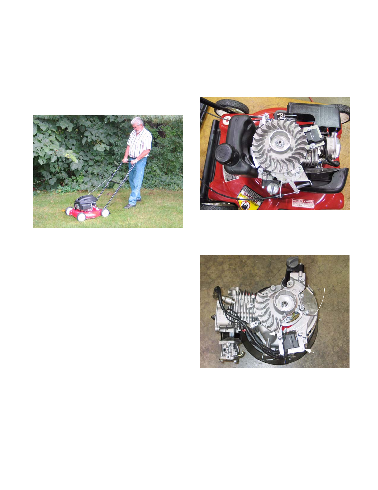
1.5. The Series 350 and Series 450 share some
basic parts. See Figure 1.5.
Series 350 / Series 450 Engine
Figure 1.5
1.6. The major castings and some architecture of the
Series 650 differs from the two smaller engines.
See Figure 1.6.
Series 650 Cut-away engine
Ignition
module
Round bulge
in carburetor
side of the
engine block
1.4. The 3rd and 4th digits are the bore in mm.
Ignition
module
Figure 1.6
1
www.mymowerparts.com

For Discount White Outdoor Parts Call 606-678-9623 or 606-561-4983
MTD Engine - Series 350/450/650
• The service procedures are similar enough that
all three engines will be covered in this manual.
• Individual differences will be noted in the text
and tables where necessary.
• The most obvious feature that distinguishes the
two engine blocks is the location of the ignition
module.
• The module is mounted above the cylinder on
the Series 350 and Series 450 engines, off-set
sligh t ly to th e in tak e si d e. S ee F i gu r e 1. 5 .
• The module is mounted about 90 degrees from
the cylinder on the Series 650 engine blocks.
See Figure 1.6.
1.7. The Series 650 engine may have a steel or plastic cam and a very robust compression release
mechanism. The Series 350 and 450 use polymer cams
1.8. While some components of the MTD engines
may be visually similar to those of other manufacturers, none of the proprietary parts are
directly interchangeable.
NOTE: The procedures detailed in this manual
are intended for use by trained technicians who
are experienced in the service and repair of outdoor power equipment. Persons who are
untrained or inexperienced in this field should
seek the assistance of an authorized service
dealer.
2. SERVICE INTENT
2.1. The engines are warranted for two years against
defects in materials and workmanship, as
described in the warranty that accompanies the
mower.
2.2. Because MTD is entering a new field, dealers
can assume that MTD will be very interested in
scrutinizing any failed parts that dealers replace
under warranty during the ‘06 and ‘07 mowing
season.
2.3. Major engine failures will be repaired using service engines, short blocks, cylinder head assemblies, or long blocks.
• The repair method will depend on the nature of
the damage to the engine. Service engines will
most-likely be prevalent.
• The dealer should do any diagnostic disassembly needed to discern lubrication and abuse failures from defects in material or workmanship,
and file a warranty claim for the time allowed.
2.4. Realistically, service will be limited primarily to
external components.
• It is not anticipated that dealers will be doing
machine-work intensive rebuilds because it is
not cost effective.
• Internal specifications that would be relevant to
such rebuilding are not included in this manual.
NOTE: This manual was developed using preproduction equipment. Although it is current and
correct at the time of writing, it is subject to
change without notice.
www.mymowerparts.com
2

For Discount White Outdoor Parts Call 606-678-9623 or 606-561-4983
MTD Engine - Series 350/450/650
3. MAJOR FAILURES NOT COVERED UNDER
WARRANTY
NOTE: The following is a list of typical non war-
rantable scenarios. It is meant to provide illustration of the intended principles of the warranty.
Non-warrantable repairs include, but are no limited to the items on this list.
3.1. Ingestion of dirt through the intake (air filter/carburetor)
3.2. Lubrication failure
3.3. Bent crankshaft
3.4. Overheated by obstructe d coolin g syste m
3.5. Corrosion or water damage
3.6. Second year carburetor failures.
4. MINOR FAILURES NOT COVERED UNDER
WARRANTY
NOTE: The following is a list of typical non war-
rantable scenarios. It is meant to provide illustration of the intended principles of the warranty.
Non warrantable repairs include, but are no limited to the items in this section.
4.1. Sheared flywheel key
4.2. Stale, out-of-date, or improper fuel
4.3. Damage from improper storage
4.4. Damage caused by animals / insects
4.5. Impact damage
4.6. Normal maintenance or adjustment items.
4.7. Recoil starter rope damage that is not the direct
result of a defect in materials or workmanship.
5. MAINTENANCE AND ADJUSTMENT INFORMATION
5.1. Fasteners: All threaded fasteners used on the
engine are metric, with the following exceptions:
• A 13/16” or 21mm wrench a re suitable for spark
plug removal.
• Series 350 and Series 450 engines are secured
to mower decks using a 3/8” self-tapping screw.
Remove them using a 9/16” wrench.
• Series 650 engines are secured to the mower
decks using metric nuts and bolts. Remove
them using a pair of 14mm wrenches.
• The crankshafts of all engines in this manual are
tapped with a 1/2”-20 thread, and the bolts can
be removed using a 5/8” wrench.
5.2. Spark plug: Torch model F7RTC, gapped to
.024”-.032” (.60-.80 mm).
• Champion RN14YC or NGK BPR4ES are physically similar but may not match the F7RTC in
heat range. This difference in heat ranges will
effect performance and emissions. It is recommended that the Torch F7RTC plug be used for
service.
• Wear rate will vary somewhat with severity of
use. If the edges of the center electrode are
rounded-off, or any other apparent wear / damage occurs, replace the spark plug before operating failure (no start) occurs.
5.3. Cleaning the spark plug:
• Use of a wire brush may leave metal deposits on
the insulator that cause the spark plug to shortout and fail to spark.
www.mymowerparts.com
• Use of abrasive blast for cleaning may leave
blast media in recesses in the spark plug. When
the media comes loose during engin e operat ion,
severe and non-warrantable engine damage
may result.
• Abrasive blast cleaning with organic media such
as walnut shells is acceptable.
5.4. Inspection of the spark plug can provide indications of the operating condition of the engine.
• Light tan colored deposits on insulator and electrodes is normal.
• Dry, black deposits on the insulator and electrodes indicate an over-rich fuel / air mixture (too
much fuel or not enough air)
3
For Discount White Outdoor Parts Call 606-678-9623 or 606-561-4983
MTD Engine - Series 350/450/650
• Wet, black deposits on the insulator and electrodes indicate the presence of oil in the combustion chamber.
• Heat damaged (melted electrodes / cracked
insulator / metal transfer deposits) may indicate
detonation.
• A spark plug that is wet with fuel indicates that
fuel is present in the combustion chamber, but it
is not being ignited.
5.5. Idle speed: If applicable, is 1,800 RPM +
RPM, set using throttle stop screw.
See Figure 5.5.
160
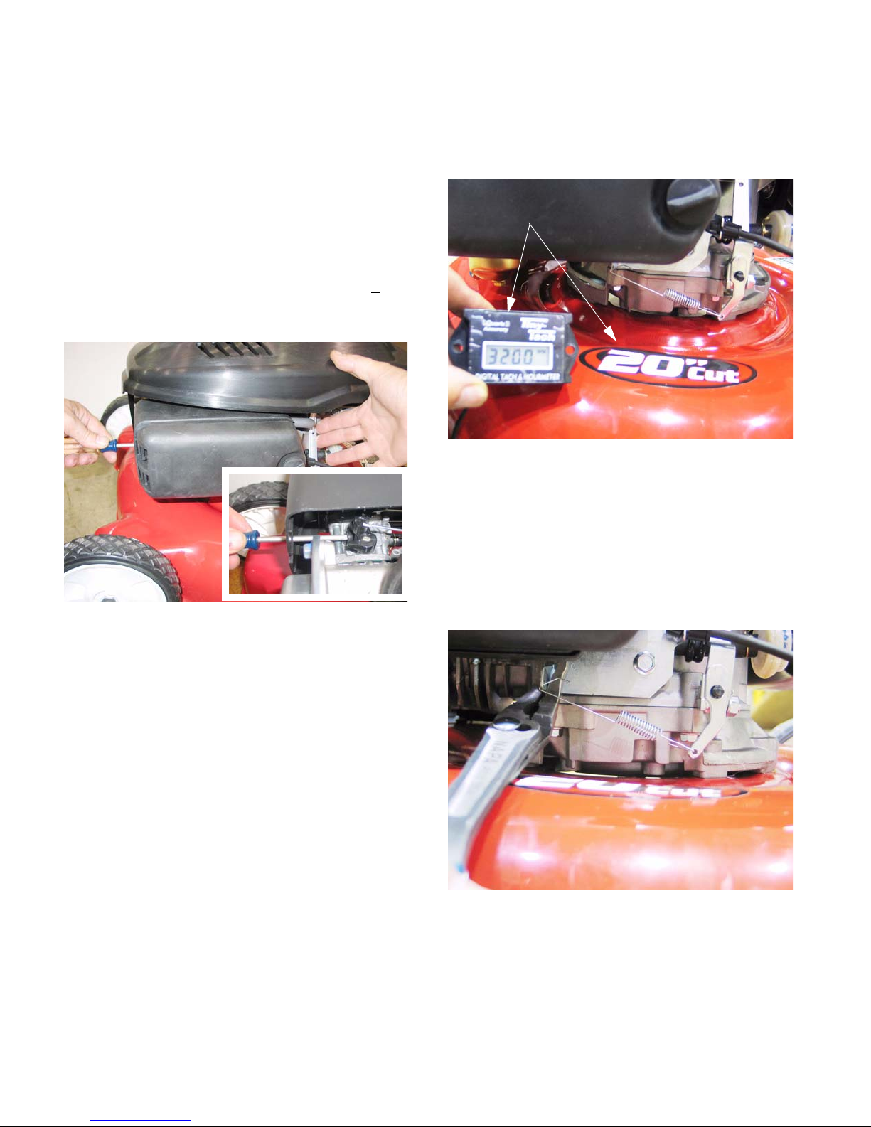
5.6. Top no-load speed varies with blade length per
ANSI B71.1-1984 standard of 19,000 feet per
minute, allowing 200 RPM for safety margin:
See Figure 5.6.
Digital tachometer confirms safe
operating speed
Figure 5.6
• 20” blade models: 3,300 RPM max., all engines.
• 21” blade models: 3,100 RPM max., all engines.
Figure 5.5
• Idle speed is not normally critical in mower applications because the operator is not provided
with a throttle control.
5.7. Top no-load speed may be adjusted slightly to
meet this specification by bending the bracket
that the governor spring connects to. The
bracket is visible under the air filter.
See Figure 5.7.
Increase spring tension to
increase engine speed
Decrease spring tension to decrease
engine speed.
Figure 5.7
www.mymowerparts.com
4
For Discount White Outdoor Parts Call 606-678-9623 or 606-561-4983
MTD Engine - Series 350/450/650
• The regulated blade tip speed is a safety feature. A dealer who puts a mower back into service with a defeated safety feature may be
subject to liability if damage or an accident
occurs.
5.8. Oil type and capacity: See Figure 5.8.
Insert but do not thread-in
dipstick to check oil level
Figure 5.8
• SAE 10W-30 SF/CD API rating for most operating conditions up to 97 deg. F. (36 deg. C.)
• 17.0 - 20.3 fl.oz. (0.5 - 0.6 liters)
• Insert but do not thread-in dipstick to check oil
level.
5.10. Oil can be drained by removing the drain plug
located at the base of the filler tube / dipstick
tube, using a 10mm wrench. See Figure 5.10.
Base of dipstick tube
Aluminum sealing washer
Drain Plug
Figure 5.10
• Replace the drain plug sealing washer with a
new one to ensure that it does not leak.
• Tighten the drain plug to a torque of 84 in-lb. (10
Nm) on installation.
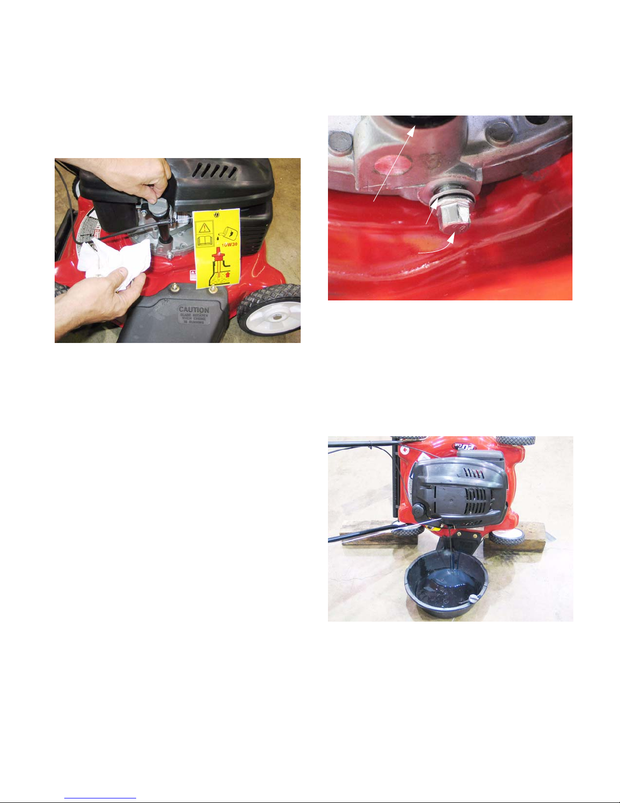
5.11. Alternatively, the mower may be tipped on its
side and the dipstick removed to drain the oil into
pre-positioned drain pan. See Figure 5.11.
• The oil level is determined by the lowest point on
the dipstick that is completely covered with oil.
5.9. Special notes on oil:
• Check the oil level more frequently and change
the oil more frequently in severe operating conditions such as high ambient temperature, dusty
conditions, or high load use in exceptionally thick
or tall grass.
• Synthetic oil may be used, but it does not extend
service intervals because the engine oil is not filtered.
• No oil additives or viscosity modifiers are recommended. The performance of oil meeting the SF/
CD specification will not be improved by the
addition of any commercially available products.
• Some oil additives may cause severe and nonwarrantable engine damage, constituting a lubrication failure.
Figure 5.11
CAUTION: Disconnect the high tension lead
from the spark plug and ground the lead before
doing any work that exposes the blade.
NOTE: If the oil is noticeable thin, or smells of
gasoline, carburetor repair will be needed before
the engine can be safely run.
www.mymowerparts.com
5
r
Val
For Discount White Outdoor Parts Call 606-678-9623 or 606-561-4983
MTD Engine - Series 350/450/650
5.12. Fuel: Use clean, fresh fuel with a pump octane
rating of 87 or greater.
• Stale or out-of-date fuel is the leading cause of
hard starting issues.
• Pump octane ratings beyond 87 will not improve
engine performance.
• The gasoline can have a maximum of 10% ethanol or 15% MTBE.
• Do not use E85 in MTD engines.
5.13. Valve lash can be checked and adjusted using
the following steps:
5.14. If the engine has been run, allow it to cool thoroughly. Position the mower for easy access to
the cylinder head.
5.15. Disconnect the high-tension lead from the spark
plug and ground it well away from the spark plug
hole.
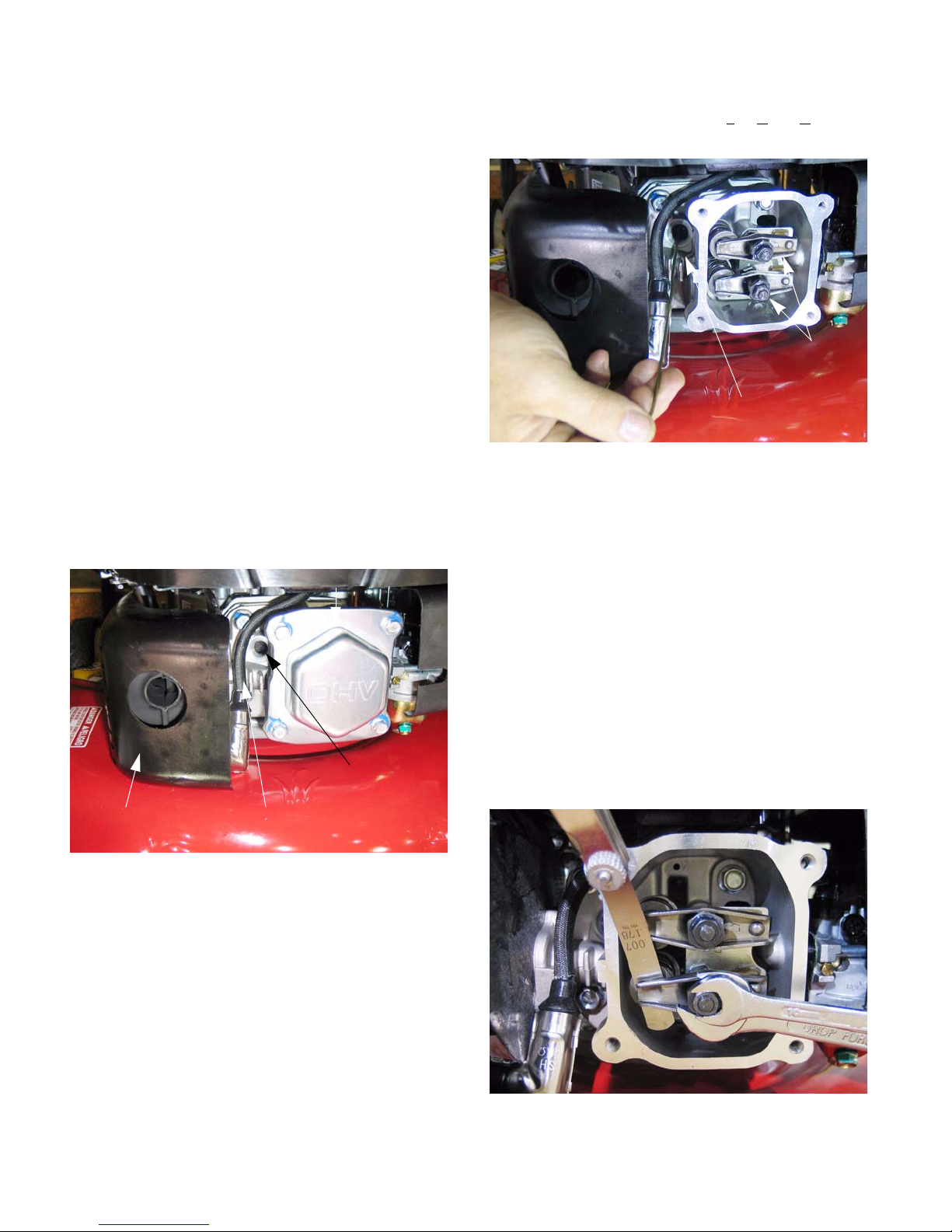
5.16. Remove the spark plug using a 13/16” or 21mm
wrench. A flexible coupling or “wobbly” extension may help. See Figure 5.16.
ve cover
5.19. Confirm that the piston is at T
the compression stroke. See Figure 5.19.
Figure 5.19
• TDC can be identified using the probe. The keyway in the PTO end of the crankshaft also corresponds with the crank pin (and piston) position.
• The compression stroke can be distinguished
from the overlap stroke by the presence of air
pressure at the spark plug hole and the fact that
neither of the valves should move significantly
on the compression stroke.
op-Dead-Center on
Valves closed
Probe to confirm piston
is at TDC
Spark plug hole
(plug removed)
High tension lead Muffle
Figure 5.16
5.17. Remove the four bolts that secure the valve
cover using a 10mm wrench, and remove the
valve cover from the engine.
NOTE: If care is used not to damage the valve
cover gasket, it can be re-used.
5.18. Secure the safety bale with a spring clamp, and
slowly pull the starter rope until air can be heard
being expelled from the spark plug hole.
• There is an automatic compression release
mechanism that “bumps” the exhaust valve as
the piston rises on the compression stroke. At
TDC, the exhaust valve should be fully closed.
5.20. Check valve lash between each valve stem and
rocker arm using a feeler gauge.
See Figure 5.20.
Setting exhaust valve lash
Figure 5.20
www.mymowerparts.com
6
For Discount White Outdoor Parts Call 606-678-9623 or 606-561-4983
MTD Engine - Series 350/450/650
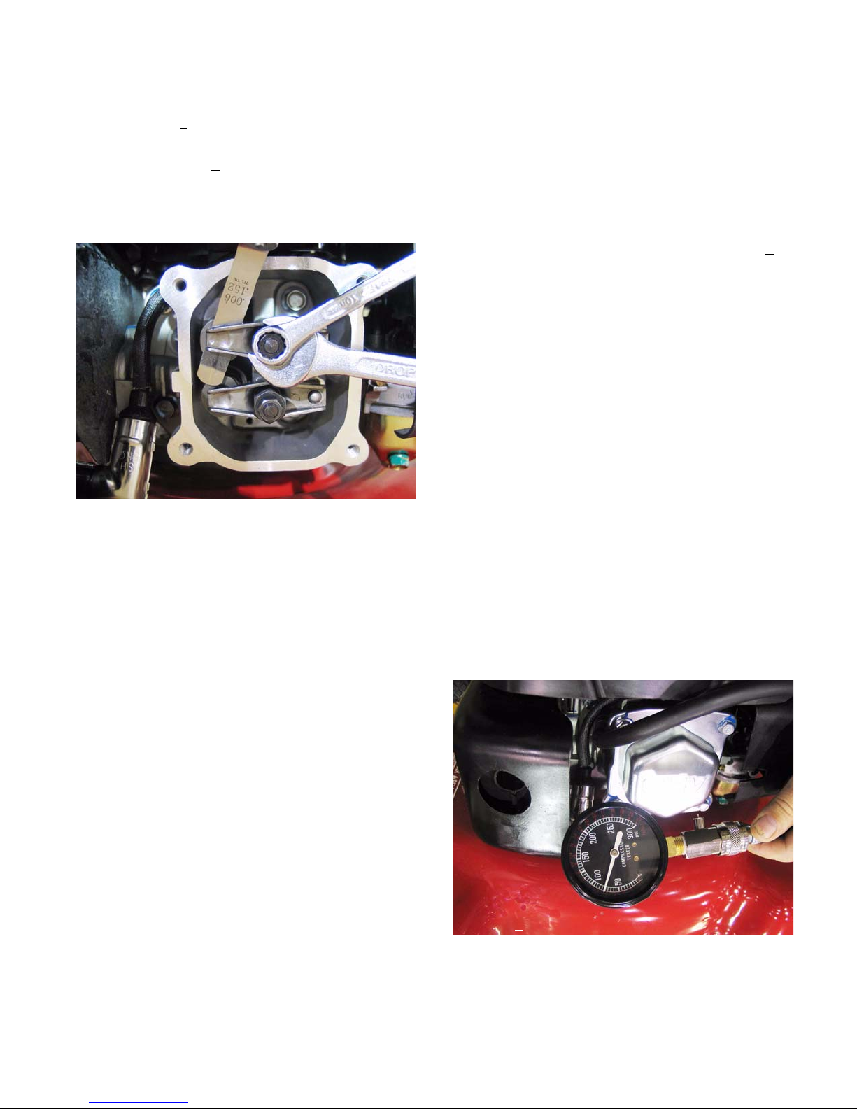
5.21. Intake valve lash (top valve) should be .003”.005” (.10 +
5.22. Exhaust valve lash (bottom valve) should be
.005-.007” (.15 +
5.23. Use a 10mm wrench to loosen the jam nut, and
a 14mm wrench to adjust the rocker arm fulcrum
nut. See Figure 5.23.
Setting intake valve lash
• Tighten the rocker arm fulcrum nut to close-up
the clearance between the end of the valve stem
and the contact point on the rocker arm.
• Loosen the rocker arm fulcrum nut to open-up
the clearance between the end of the valve stem
and the contact point on the rocker arm.
5.24. Hold the fulcrum nut with a 14mm wrench,
tighten the jam nut to a torque of 88.5 in-lb.
(10Nm) using a 10mm wrench.
.02mm).
.02mm).
Figure 5.23
5.28. Install the valve cover, tightening the valve cover
screws to a torque of 71 in-lb (8 Nm).
5.29. Install the spark plug and tighten to a torque of
177-221 in-lbs (20 - 25 Nm).
5.30. Release the spring clamp securing the safety
bail, start the engine and test run it long enough
to confirm correct operation.
5.31. Compression should be in the range of 70 +
PSI (5.2 +
5.32. If the engine has been run, allow it to cool thoroughly.
5.33. Disconnect the high-ten sion lead from the spark
plug and ground it well away from the spark plug
hole. See Figure 5.16.
5.34. Remove the spark plug using a 13/16” or 21mm
wrench. A flexible coupling or “wob bly” extension may help.
5.35. Hold the safety bail and pull the starter rope se veral times to purge any fuel or oil from the combustion chamber.
NOTE: Air compresses readily, liquid does not.
Liquid in the combustion chamber will result in
an artificially high compression reading.
5.36. Install a compression gauge in the spark plug
hole.
5.37. Confirm that the gauge is “zeroed”, then hold the
safety bail and pull the starter rope repeatedly,
until the needle on the gauge has risen as far as
it is going to. See Figure 5.37.
1.7 Bar).
25
5.25. Double-check the clearance after tightening the
jam nut, to confirm that it did not shift. Re-adjust
if necessary.
5.26. Rotate the engine through several compression
cycles:
• Observe the movement of the valve train.
• Return the piston to TDC compression stroke
and re-check the valve lash to confirm consistent
movement of the valve gear, including the slight
bump to the exhaust valve from the automatic
compression release.
5.27. Clean-up any oil around the valve cover opening, clean the valve cover, replace the valve
cover gasket if necessary.
www.mymowerparts.com
Compression gauge
Reading ~
7
90 PSI
Figure 5.37
For Discount White Outdoor Parts Call 606-678-9623 or 606-561-4983
MTD Engine - Series 350/450/650
5.38. Interpreting compression readings:
• Near Zero (< 20PSI [1.38 Bar]): most likely a
stuck valve or too-tight valve lash, provided
starter rope pulls with normal effort.
• Moderately low (20-45 PSI [1.38 - 3.1Bar]):
Valve seat damage or piston ring wear.
Leak-down test or compressed-air test will help
confirm if damage is isolated to valves or piston
rings.
Oil smoke in exhaust on throttle increase tends
to indicate piston ring wear.
Oil smoke in exhaust on over-run tends to indicate valve guide wear.
• Too high compression (>95 PSI [>6.55 Bar])
most likely indicates excessive valve lash,
negating the automatic compression release. It
may also indicate a partial hydraulic lock or
severe carbon deposits within the cylinder.
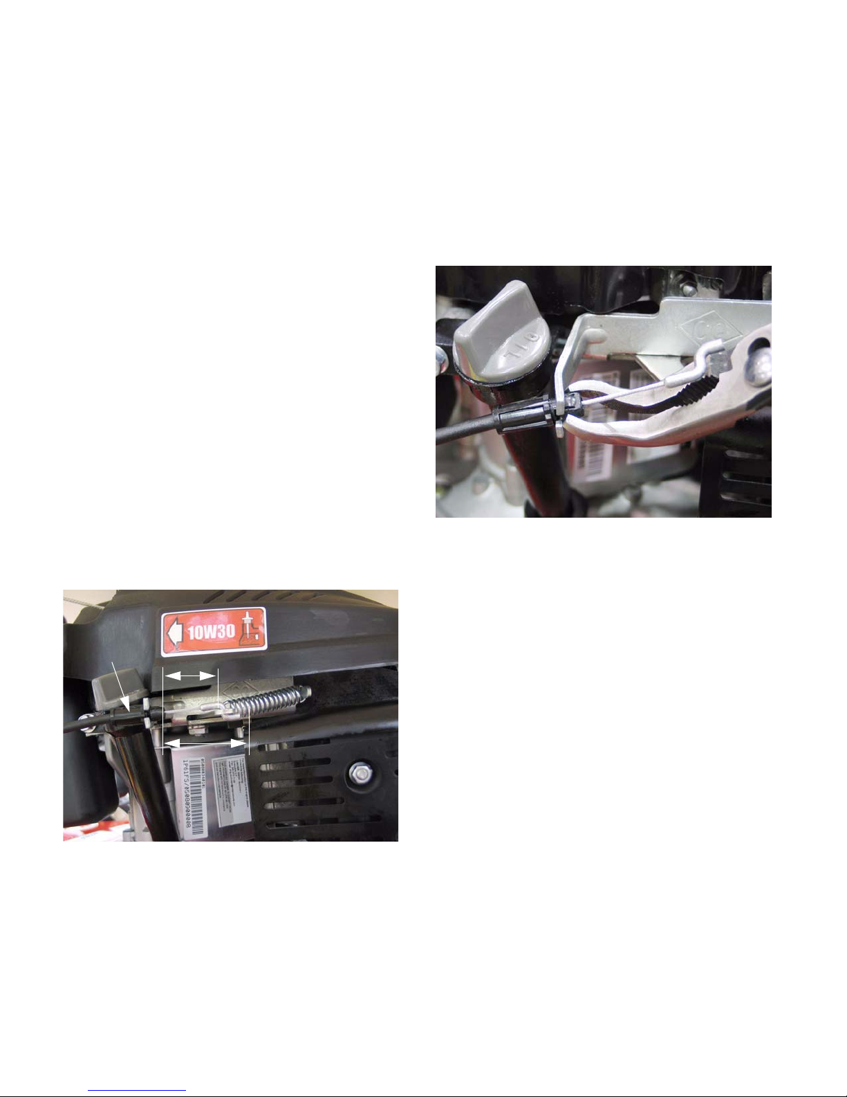
5.39. Stop switch and brake: The stop switch and
brake must be able to stop the blade from rotating within 3.0 seconds after the release of the
safety bail, per ANSI B71.1-2003 standard.
• The cable should not bind. Replace the cable if
it is kinked, melted frayed, or damaged in an y
other way that causes it to bind.
• The brake arm on the engine should not bind.
• Each can be lubricated with light penetrating oil
or a dry PTFE-based lubricant such as “Tri-Flow”
dry Teflon lubricant.
5.42. To replace the cable: See Figure 5.42.
Releasing the engine control
cable from the bracket
5.40. Make sure that the mower conforms to these
standards by performing a stop test.
5.41. Check the movement of the cable and brake
mechanism. See Figure 5.41.
Engine control
cable
Safety bail in RUN position
Safety bail in OFF position
Figure 5.41
Figure 5.42
• Squeeze the safety bail ends together to release
the bail from the upper handle bar.
• Releasing the bail from the handle bar will provide enough slack in the cable to unhook the Zfitting at the top of the cable from the bail.
• After the bail end of the cable is unhooked, the
Z-fitting at the engine end of the cable can be
unhooked.
• Squeeze the barbs together at the engine end of
the cable housing to disconnect it completely
from the engine.
• Remove the nut and bolt that secure the cable to
the handle bar .
• Reverse the removal process to install the cable,
then test the mower in a safe area before returning it to service.
5.43. The brake pad should be replaced when the
thickness of the friction material is less than .25”
(6.35mm) at the thinnest spot.
www.mymowerparts.com
8
For Discount White Outdoor Parts Call 606-678-9623 or 606-561-4983
MTD Engine - Series 350/450/650
5.44. To replace the brake pad, remove the flywheel
as described in the IGNITION section of this
manual. See Figure 5.44.
Brake pad
Nuts
Figure 5.44
5.45. Remove the two nuts that hold the brake pad to
the brake arm using an 8mm wrench, and
remove the pad.
5.46. Apply a small amount of thread locking compound such as Loctite 242 (blue) to th e thre ade d
studs on the new brake pad, and fasten it to the
brake arm using the two nuts previously
removed.
5.47. Assemble the engine, reversing the disassembly
process. Adjust the brake arm if necessary.
5.48. Adjust the brake arm with the flywheel
installed, but the fan shroud, recoil assembly,
and engine cover removed.
5.49. There are two screws that hold the brake
assembly to the engine. They can be loosened
using an 10mm wrench. See Figure 5.49.
Screw:
pivot point
Screw:
Adjustment
Figure 5.49
• The screw near the base of the cylinder is a
pivot point.
• The screw near the oil fill tube clamps the brake
mechanism in place via a slotted hole.
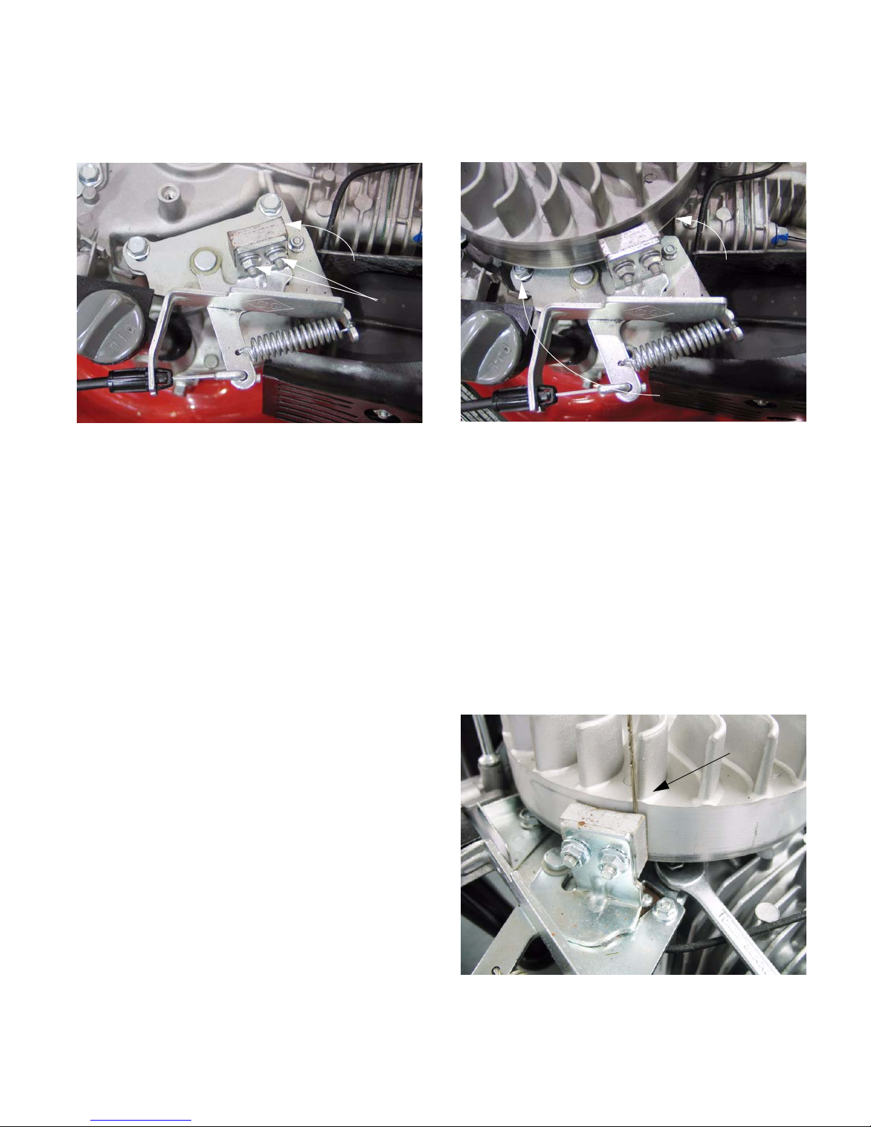
5.50. Use a spring clamp to hold the safety bail
against the upper handle bar.
5.51. Position the brake assembly so that the edge of
the brake pad that is nearest the slotted hole is
roughly .050” (1.27mm) from the flywheel, then
tighten the screws. See Figure 5.51.
NOTE: The shank of an unused drill bit may be
used as a feeler gauge
www.mymowerparts.com
Drill bit used
for gauge
Figure 5.51
9
For Discount White Outdoor Parts Call 606-678-9623 or 606-561-4983
MTD Engine - Series 350/450/650
5.52. Run and test the mower in a safe area before
returning it to service.
5.53. To test the stop switch: locate the terminal that
connects the stop switch wire to the primary
windings of the ignition module.
See Figure 5.53.
Stop switch
Wire to
ignition model
Figure 5.53
5.54. Connect an Ohm meter between the terminal
and a ground point. The reading should
approach zero when the bail is released, closing
the contacts. See Figure 5.54.
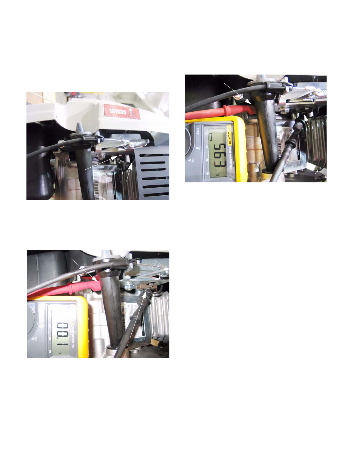
5.55. The reading should be high when the bail is
pulled down, reflecting the resistance in the primary windings of the ignition module.
See Figure 5.55.
Ground connection
Safety bail
in RUN
position
Stop switch
connection
Figure 5.55
5.56. Alternatively, a jumper wire could be connected
to the same locations. Use a commercially
available spark checker to see if the ignition is
working or not.
• If the jumper disables the ignition, but releasing
the bail does not, the problem lies in the switch.
Ground connection
Safety bail in
OFF position
Figure 5.54
Stop
switch
connection
• If the jumper does not disable th e ignition, then
the wire that connects the switch to the ignition
may have a fault, or the ignition module itself
may be faulty. Further investigation is required.
• If the problem is a lack of spark when the bail is
pressed against the upper handlebar, disconnect
the wire from the switch using a 7mm wrench.
Isolate the wire from incidental contact with
ground, and test the ignition.
If it fails to spark, the wire may be shorted or the
ignition may be at fault. Further investigation is
required.
www.mymowerparts.com
10
 Loading...